Skip to the content
2 layers22.1 × 17.3 mmRotary breakout, the printed circuit board in 3D

A simple rotary encoder breakout board

Size
22.1 × 17.3 mm
Copper layers
2
Thickness
1.6 mm
Parts
3
Nets
4
Pads
11
Tracks, vias
7, 0
Pours
2
Routed
Yes
KiCad
KiCad 4
Created
22 Jan 2018
Updated
22 Jul 2020

Overview

Rotary breakout is an open-source printed circuit board by mtrudel, from the mtrudel/rotary_breakout repository on GitHub. It is a 2-layer board of 22.1 × 17.3 mm with 3 parts on 4 nets, routed with 7 tracks and 0 vias.

Its parts include 1 connector and 1 switch. It belongs with the interfaces and adapters and microcontroller boards boards of this library.
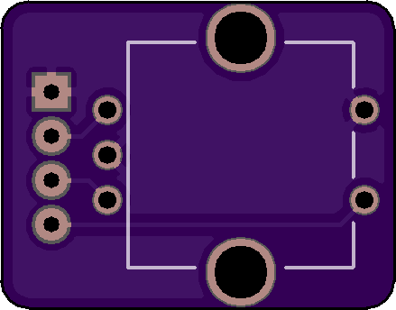
README

README.md

Rotary Breakout

A simple breakout board for PEC11 rotary encoders (as sold by Adafruit).

Designed to be paired with a 4 pin JST header

Pinouts in the above image from top to bottom are:

  • Ground
  • A (quadrature trigger)
  • B (quadrature direction)
  • Z (button press)

Usage Guide

If you're new to rotary encoders, their use can be non-obvious. The typical approach I take is to:

  1. Set up pullup resistors on both pins A and B.
  2. Set up an edge triggered GPIO monitor on pin A, looking at rising edges only.
  3. When you see a rising edge on A, immediately read the value of B. If it's high, you just rotated clockwise. If it's low, you just rotated counter-clockwise.

Available at OSH Park

License

MIT

Parts

3
QtyValueFootprintReferences
1Conn_01x04Connectors_JST:JST_EH_B04B-EH-A_04x2.50mm_StraightJ1
1ENCODER-SWITCHSwitches:ROTARY_ENC_PLAINS1
1LOGOmoshozenfootprints:MoshozenG***

Similar boards

  • 2 layers40 × 30 mmBlinky, the printed circuit board in 3D

    Blinky

    earthtojake/text-to-cad

    Design physical products with AI

    3 parts26kMIT
  • 2 layers51.9 × 16 mmPassive2-rpi non standard adapter, the printed circuit board in 3D

    Passive2-rpi non standard adapter

    hzeller/rpi-rgb-led-matrix

    Controlling up to three chains of 64x64, 32x32, 16x32 or similar RGB LED displays using Raspberry Pi GPIO

    3 parts4.4kGPL-2.0
  • 2 layers16.3 × 16.3 mmSensor, the printed circuit board in 3D

    Sensor

    scottbez1/splitflap

    DIY split-flap display

    3 parts4.2k
  • 2 layersSub, the printed circuit board in 3D

    Sub

    atopile/atopile

    Design circuit boards with code! ✨ Get software-like design reuse 🚀, validation, version control and collaboration in hardware; starting with electronics ⚡️

    3 parts4kMIT
  • 2 layers85 × 30 mmDual stomp, the printed circuit board in 3D

    Dual stomp

    torvalds/GuitarPedal

    Linus learns analog circuits

    3 parts2.5kGPL-2.0
  • 2 layers124.5 × 33.7 mm172319-1 connector, the printed circuit board in 3D

    172319-1 connector

    rusefi/rusefi

    rusefi - GPL internal combustion engine control unit

    3 parts1.2k
  • 2 layers10.5 × 83 mmProgrammingAdapter, the printed circuit board in 3D

    ProgrammingAdapter

    stuartpittaway/diyBMSv4

    Version 4 of the diyBMS

    3 parts1.1k
  • 2 layers21.2 × 51.3 mmPico reset, the printed circuit board in 3D

    Pico reset

    hackclub/sprig

    🍃 Learn to code by making games in a JavaScript web-based game editor.

    3 parts1.1kMIT

Questions

How big is the Rotary breakout PCB?

It measures 22.1 × 17.3 mm and has 2 copper layers, 1.6 mm thick.

What parts does the Rotary breakout use?

3 parts. The full list of its parts is on this page, with links to each part's symbol and footprint where PCBKit's library has them.

Where can I download the Rotary breakout KiCad files?

From the mtrudel/rotary_breakout repository on GitHub, at the commit this page was made from: the board is rotary_breakout.kicad_pcb. PCBKit opens the board in the browser, with nothing to install.

Can I use the Rotary breakout design in my own project?

Its repository states no licence, so its author keeps all rights: ask mtrudel before reusing the design.