2 layers150.1 × 73.9 mm
Relay Module
MSTRocketDesignTeam/TestStand-Instrumentation-PCB
Rocket Team's Instrumentation Interface PCB
49 partsGPL-3.0
 MSTRocketDesignTeam/TestStand-Instrumentation-PCB
Rocket Team's Instrumentation Interface PCB
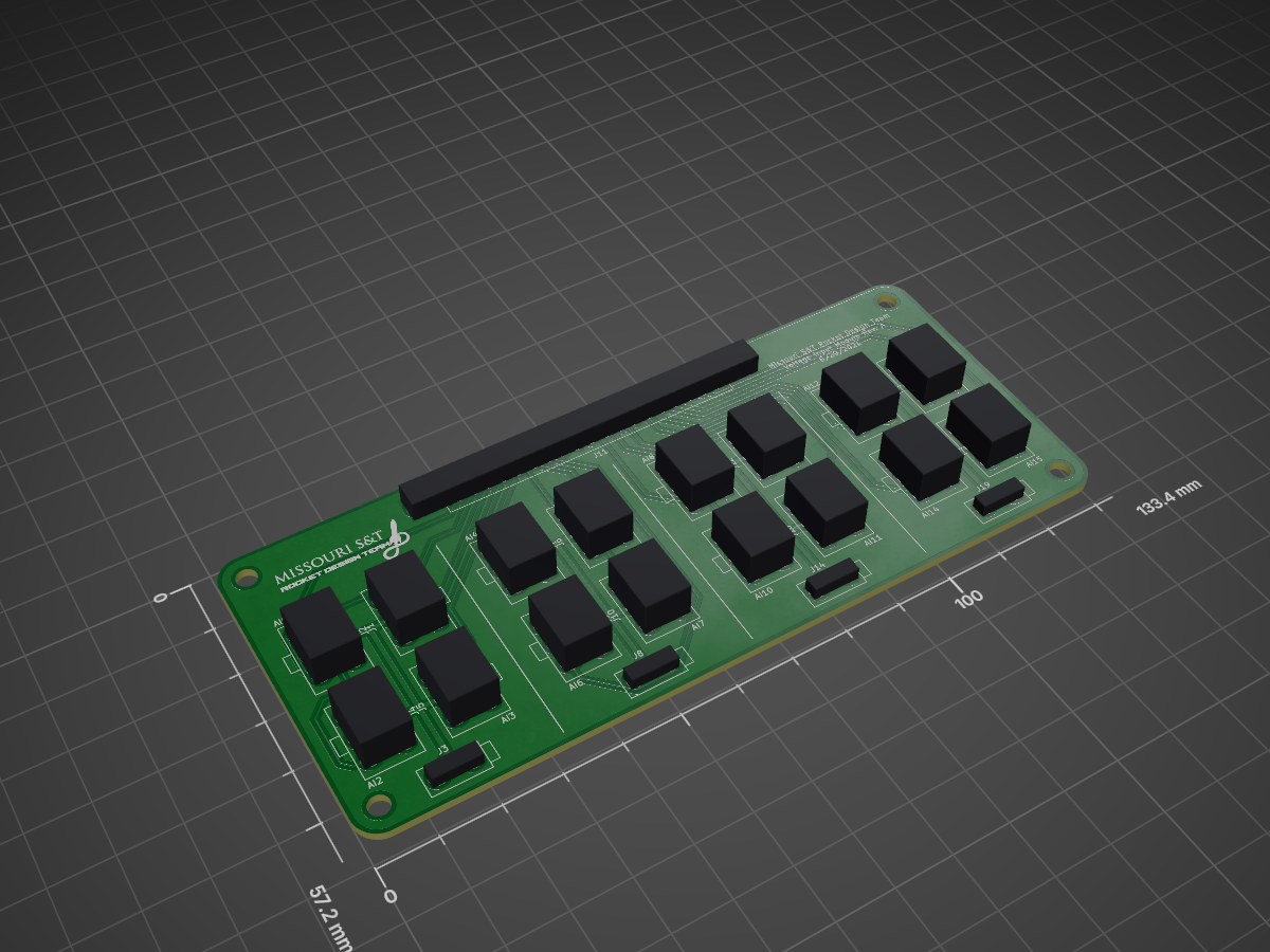
Voltage Input Module is an open-source printed circuit board by MSTRocketDesignTeam, from the MSTRocketDesignTeam/TestStand-Instrumentation-PCB repository on GitHub, published under the GPL-3.0 licence. It is a 2-layer board of 133.4 × 57.2 mm with 22 parts on 58 nets, routed with 310 tracks and 0 vias.
This repo will hold all of the relevant design files for the Rocket Design Team's Test Stand.
| Qty | Value | Footprint | References |
|---|---|---|---|
| 16 | 0039288060 | custom-footprint-library:0039288060 | J1, J2, J4, J5, J6, J7, J9, J10, J12, J13, J15, J16, J17, J18, J20, J21 |
| 4 | 0039281023 | custom-footprint-library:0039281023 | J3, J8, J14, J19 |
| 1 | logo-footprints:LOGO | LOGO | |
| 1 | 182-037-213 | custom-footprint-library:182-037-213R181 | J11 |
MSTRocketDesignTeam/TestStand-Instrumentation-PCB
Rocket Team's Instrumentation Interface PCB

MSTRocketDesignTeam/TestStand-Instrumentation-PCB
Rocket Team's Instrumentation Interface PCB

MSTRocketDesignTeam/TestStand-Instrumentation-PCB
Rocket Team's Instrumentation Interface PCB

MSTRocketDesignTeam/TestStand-Instrumentation-PCB
Rocket Team's Instrumentation Interface PCB

MSTRocketDesignTeam/TestStand-Instrumentation-PCB
Rocket Team's Instrumentation Interface PCB

VoronDesign/Voron-Hardware
Cool Hardware designed by the Voron Design group

hoglet67/RGBtoHDMI
Bare-metal Raspberry Pi project that provides pixel-perfect sampling of Retro Computer RGB/YUV video and conversion to HDMI

hackclub/OnBoard
💡 Join 1,000 teenagers and make your first PCB with a $100 grant!

abhishek-kakkar/BeagleLogic
A Software Suite that implements a logic analyzer with the PRU on the BeagleBone / BeagleBone Black.

Chrismettal/flipper-zero-backpacks
Backpack-style addon boards for the Flipper Zero!


CRImier/MyKiCad
My KiCad boards. Can't be bothered uploading individually anymore, so here you go.
It measures 133.4 × 57.2 mm and has 2 copper layers, 1.6 mm thick.
22 parts. The full list of its parts is on this page, with links to each part's symbol and footprint where PCBKit's library has them.
From the MSTRocketDesignTeam/TestStand-Instrumentation-PCB repository on GitHub, at the commit this page was made from: the board is V1-OLD/Voltage Input Module/Voltage_Input_Module.kicad_pcb and its schematic AI_Board_RevA/AI_Board_RevA.kicad_sch. PCBKit opens the board in the browser, with nothing to install.
Its repository publishes it under the GPL-3.0 licence: you may reuse it on that licence's terms (keep the author's notice, and for a copyleft licence share your changes alike).