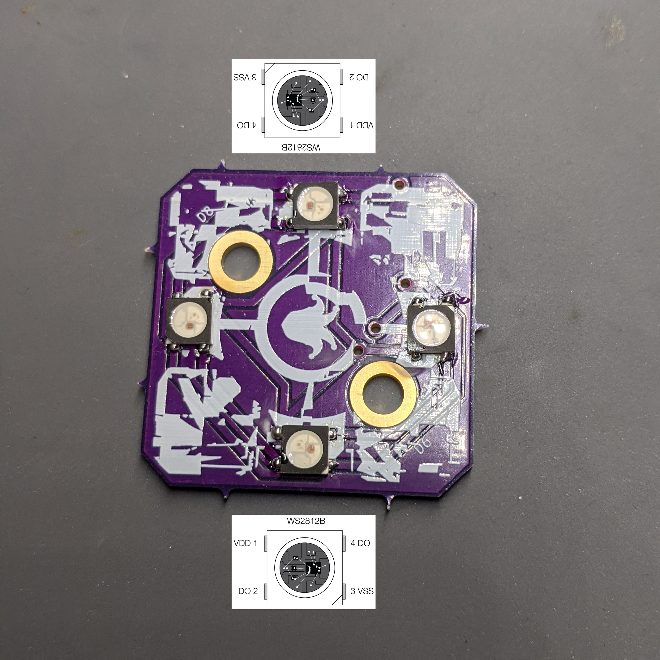
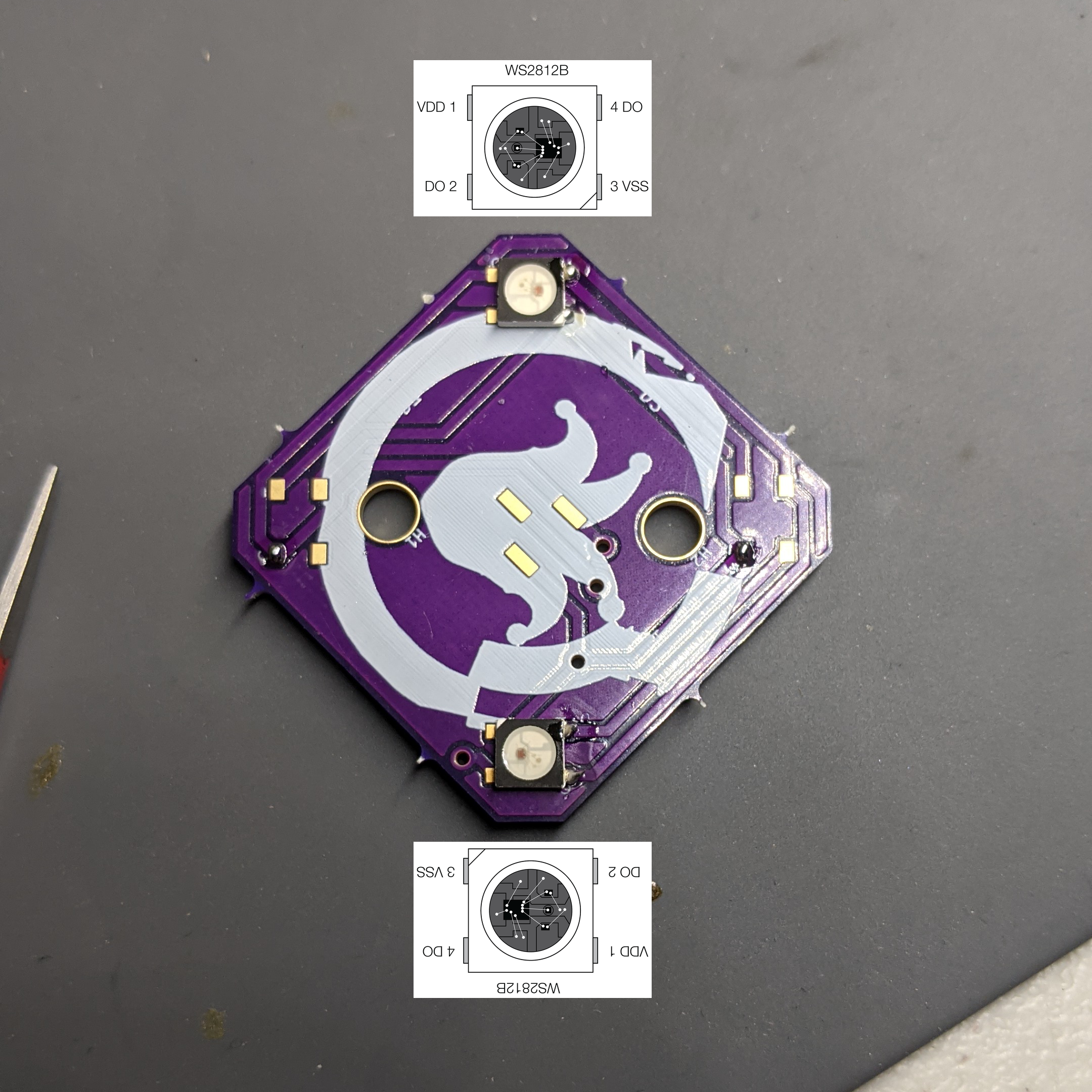
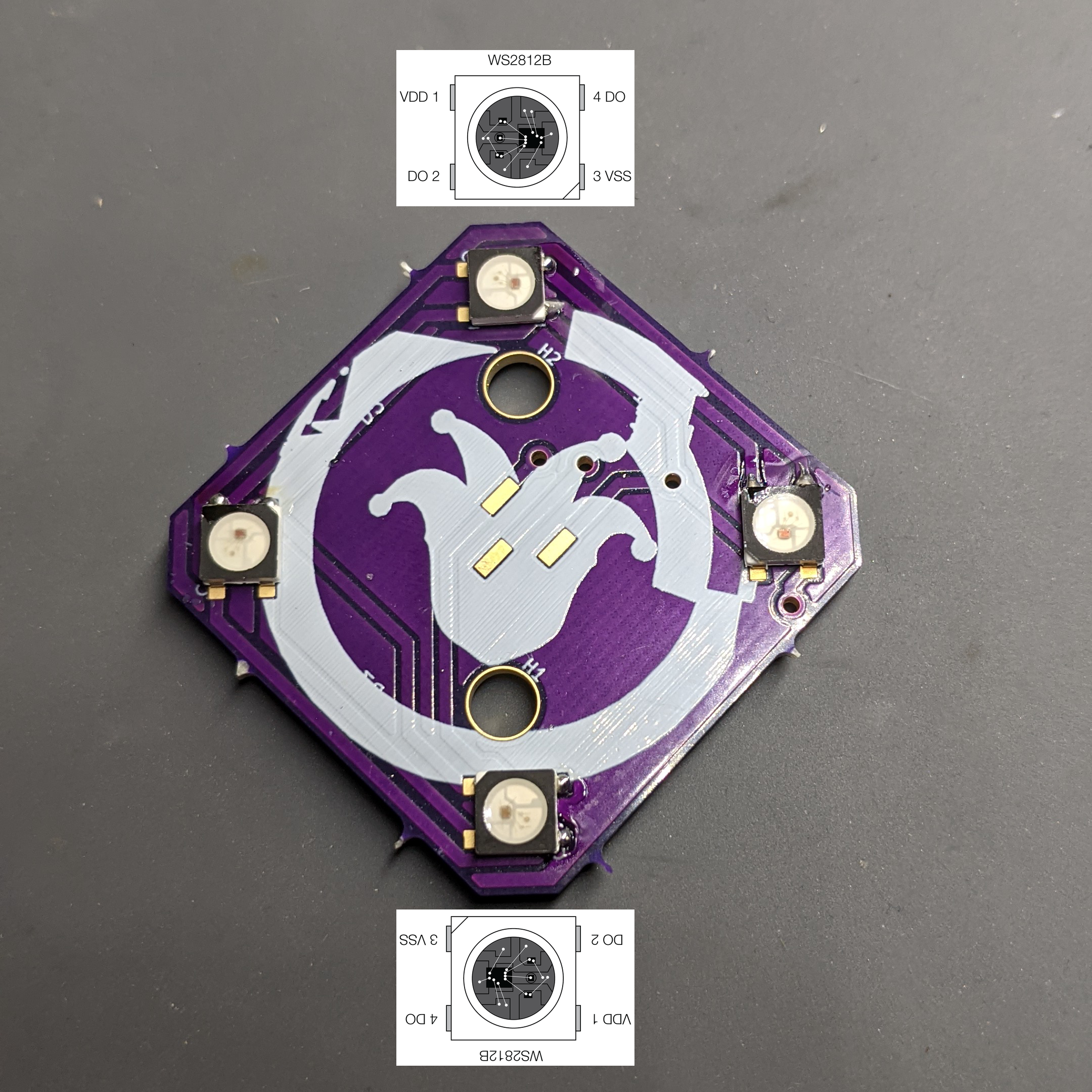
Companion
- Size
- 34.8 × 34.8 mm
- Copper layers
- 2
- Thickness
- 1.6 mm
- Parts
- 13
- Nets
- 28
- Pads
- 56
- Tracks, vias
- 103, 17
- Pours
- 2
- Routed
- Yes
- KiCad
- KiCad 6 (file 20211014)
- Created
- 23 Oct 2022
- Updated
- 25 Oct 2022
Overview
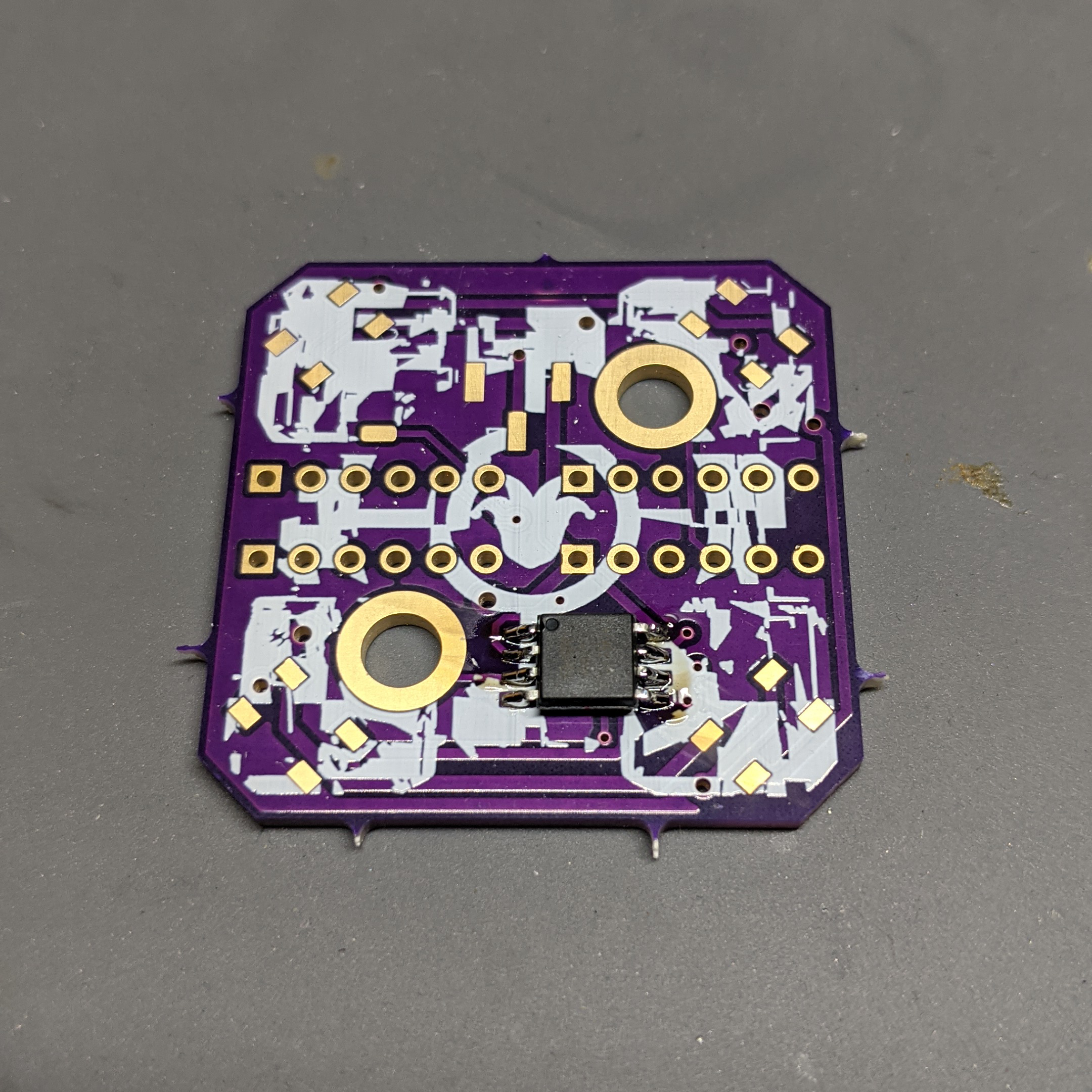
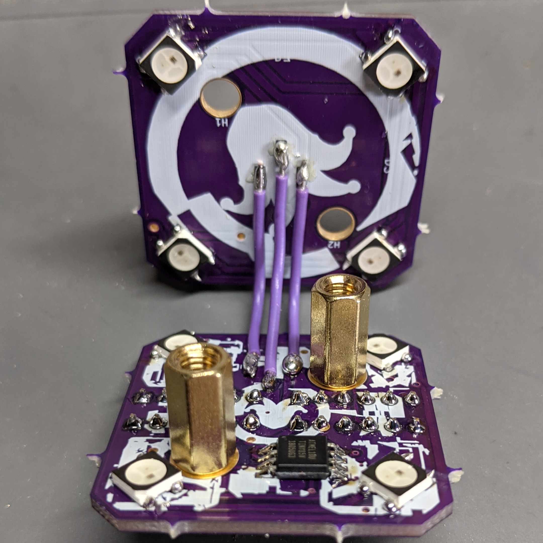
Companion is an open-source printed circuit board by mspicer, from the mspicer/hitb2022 repository on GitHub. It is a 2-layer board of 34.8 × 34.8 mm with 13 parts on 28 nets, routed with 103 tracks and 17 vias.
It is built around the ATTINY85-20SU and WS2812B. Its parts include 6 connectors, 4 diodes and 1 IC. It belongs with the AVR (ATmega, ATtiny) boards of this library.
Main components
2README
README.mdHack-in-the-box 2022 Badge Guide
- PCB.md contains the schematics and pcb layout for each board. This may be helpful for assembly or programming.
- PROGRAM.md contains information on flashing the boards with the current or custom code if desired.
Assembly
Step 1
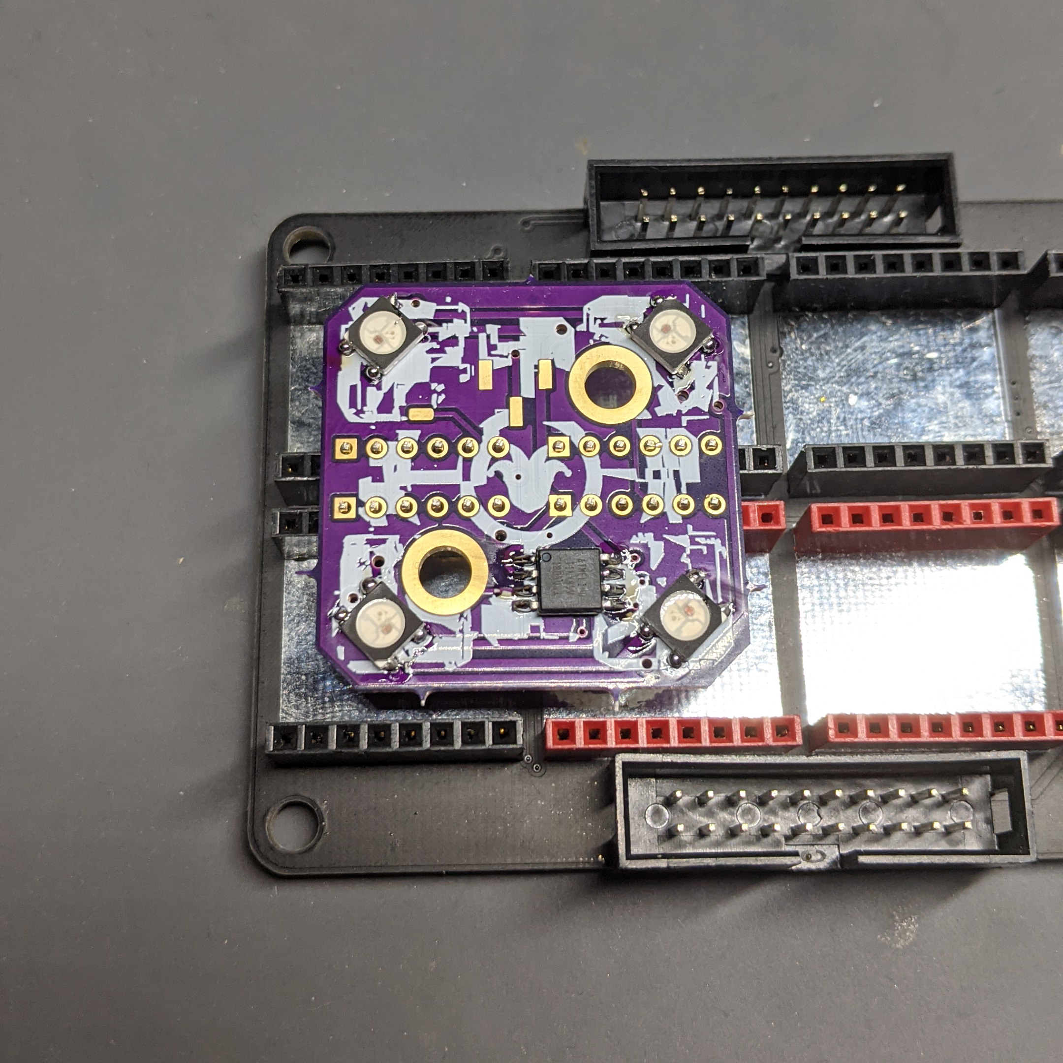
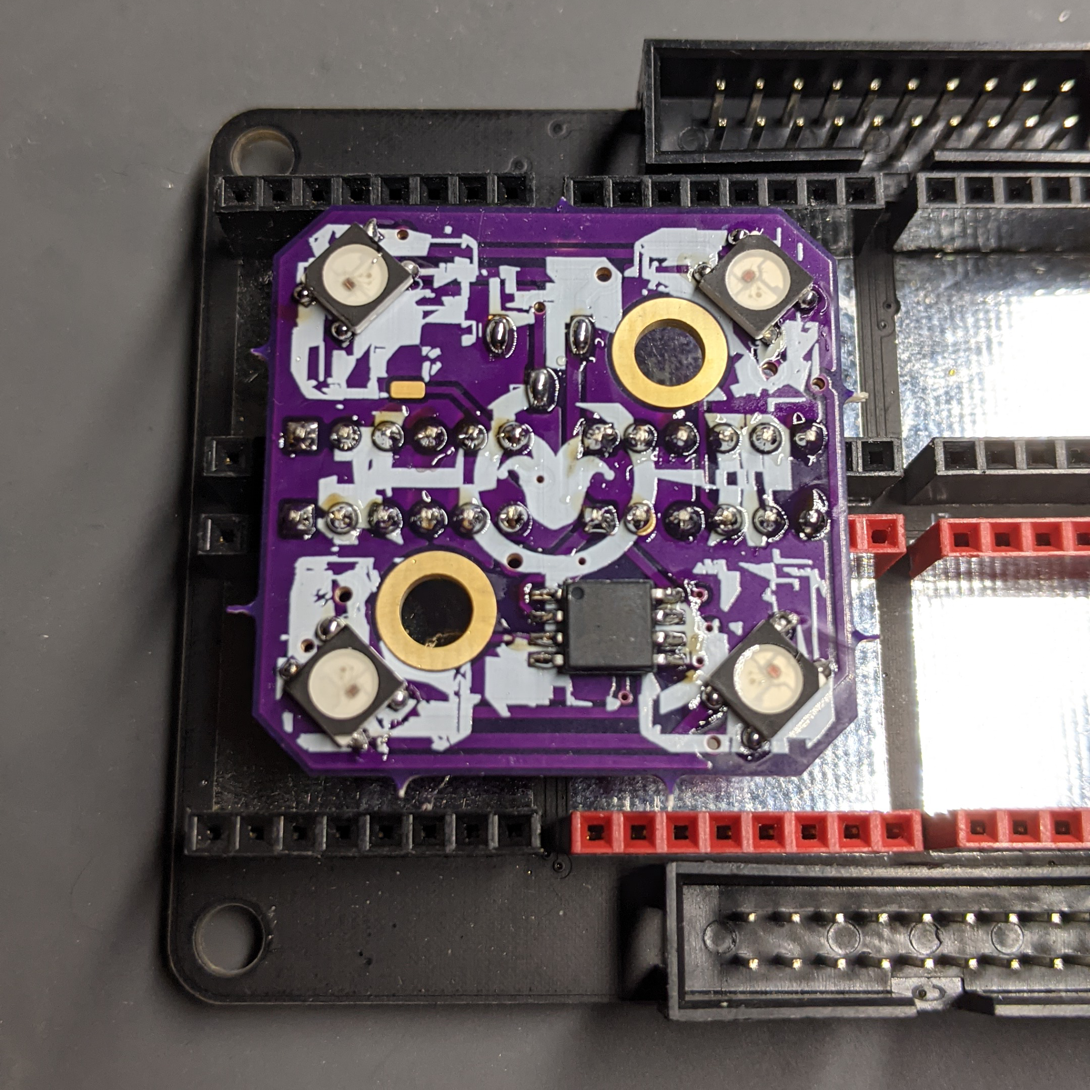
- Solder the attiny85 to the base pcb.

Step 2
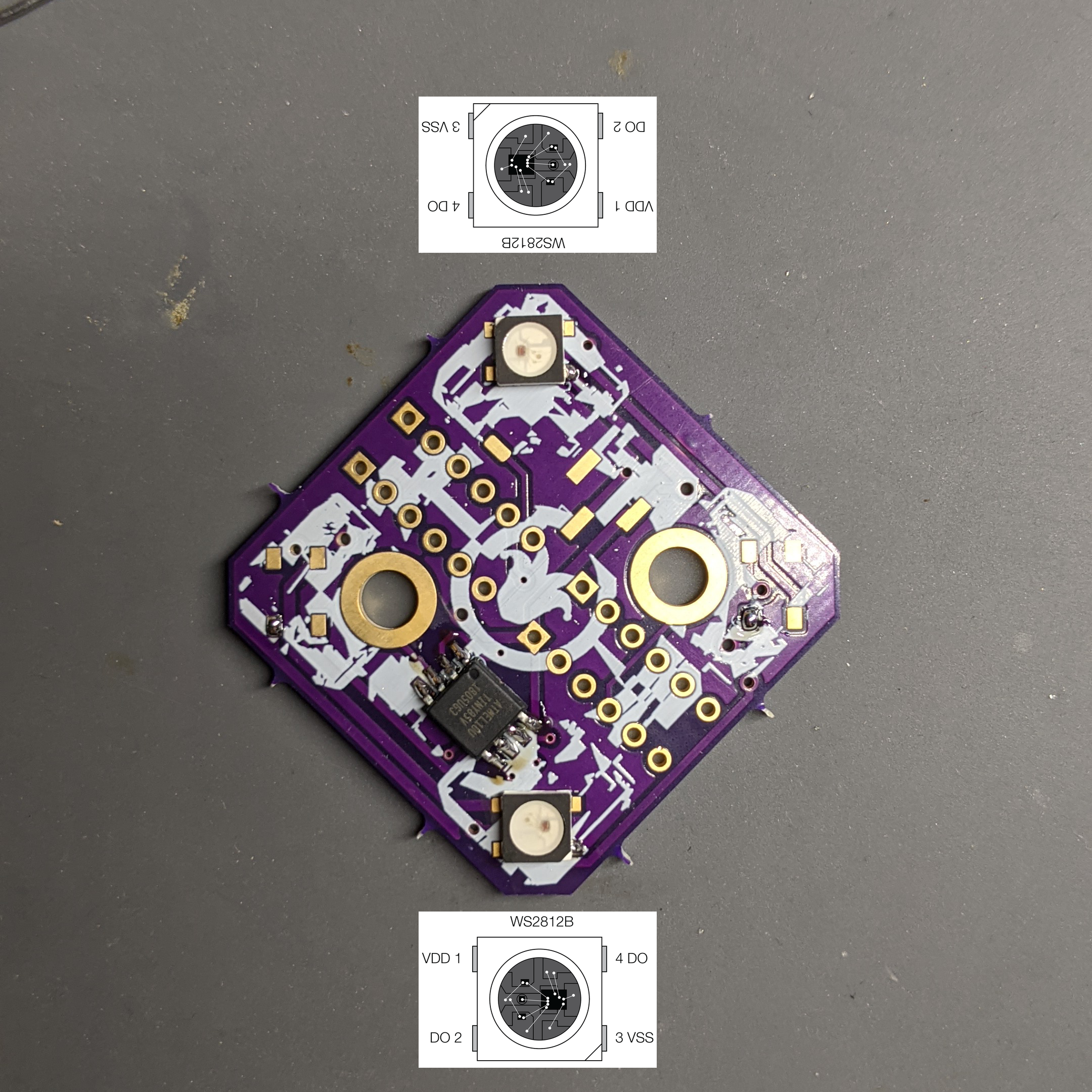
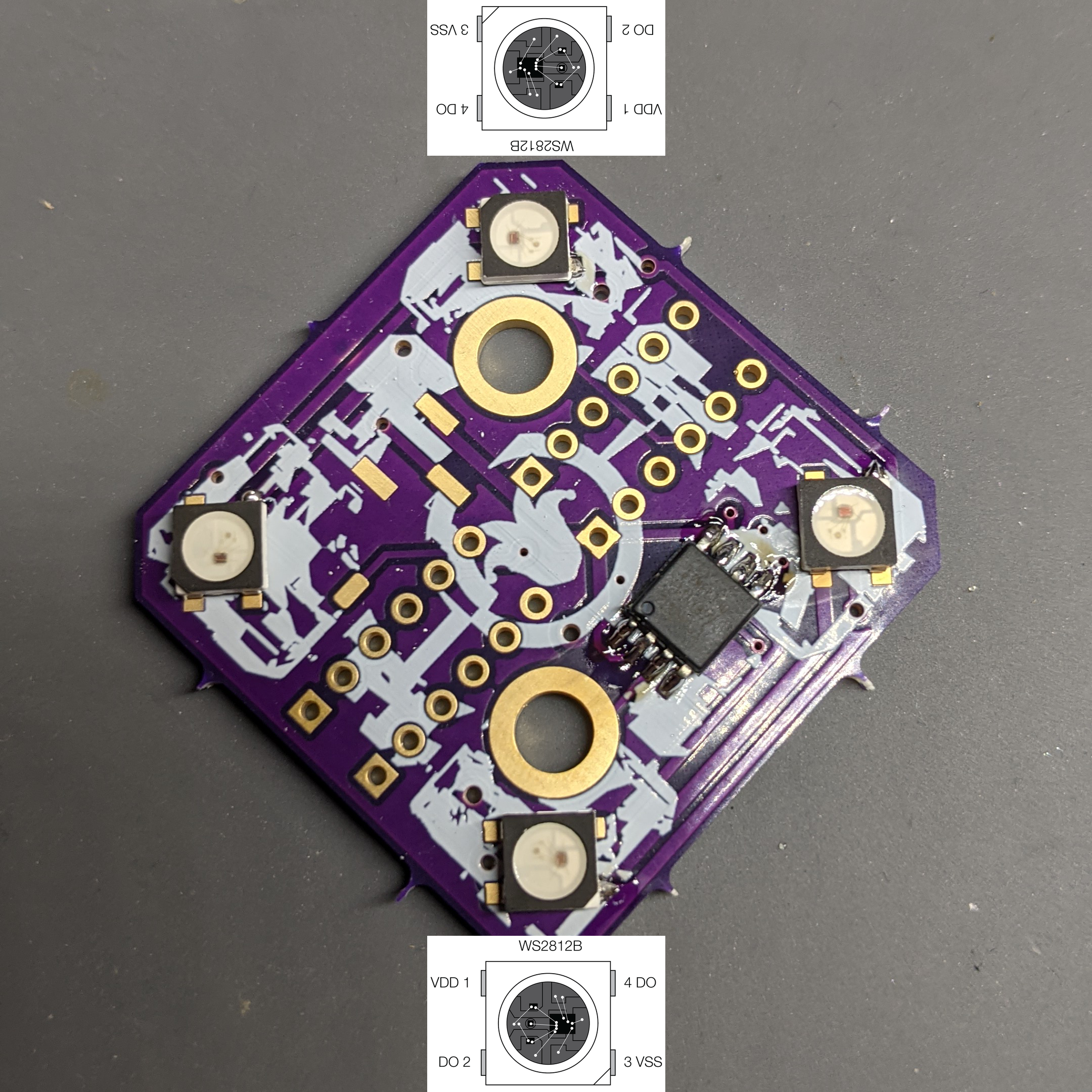
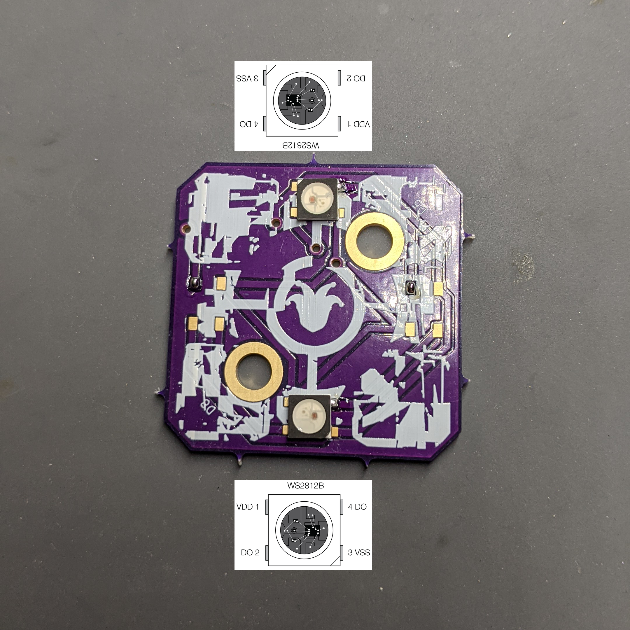
- Solder the first two leds on the base pcb.

Step 3
- Solder the last two leds on the base pcb.

Step 4
- Solder the first two leds on the top of the upper pcb.

Step 5
- Solder the next two leds on the top of the upper pcb.

Step 6
- Solder the first two leds on the bottom of the upper pcb.

Step 7
- Solder the last two leds on the upper pcb.

Step 8
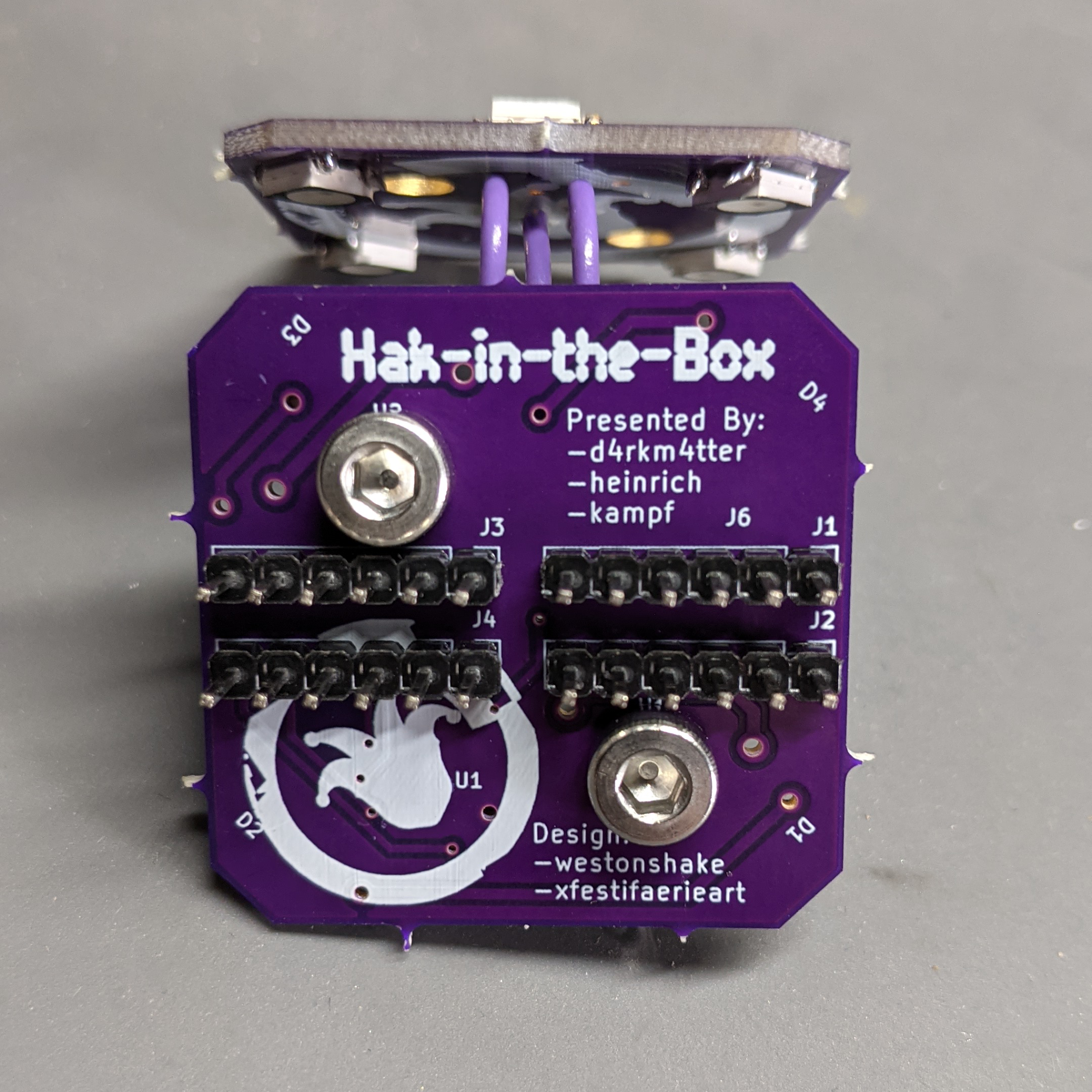
- Solder the headers on the board by first placing them in the expansion board or similar and then slide the board on to ensure good fit.

Step 9

Step 10
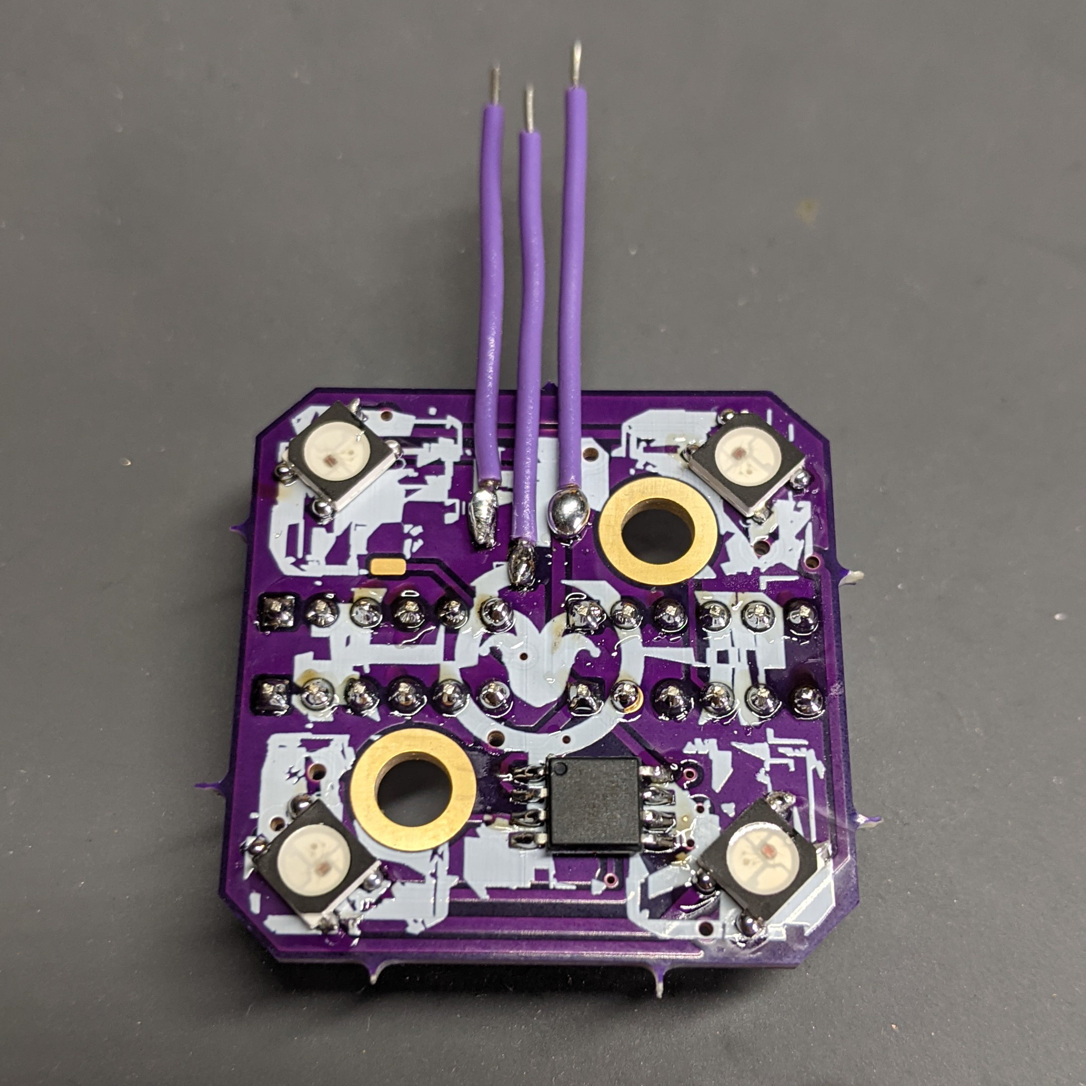
- Remove the stripped ends of the three solid-core wires and attach them to the base pcb.

Step 11
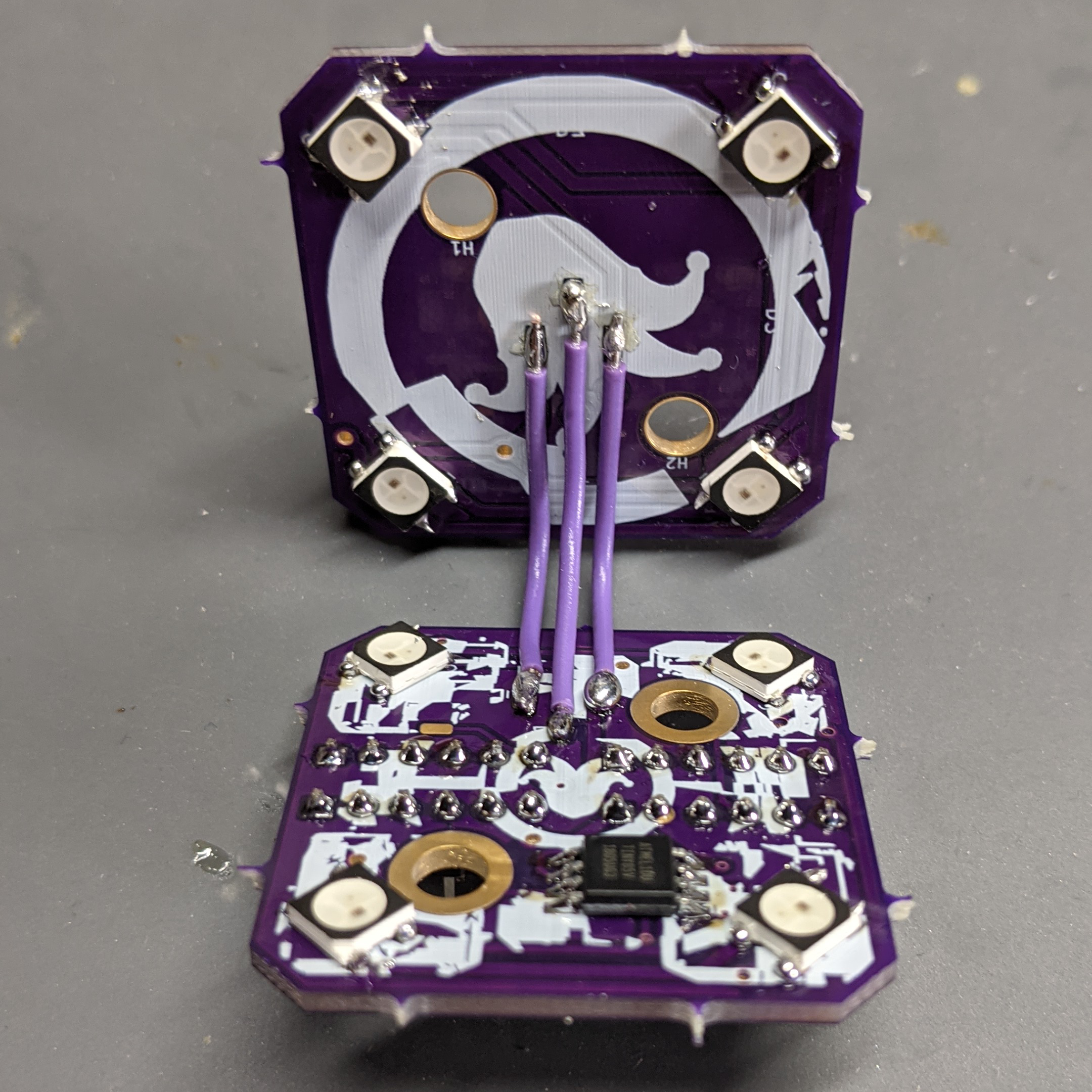
- Solder the solid-core wires to the top. The easiest way is to solder the outer two wires, bend them all 90 degrees, then solder the middle one.

Step 12
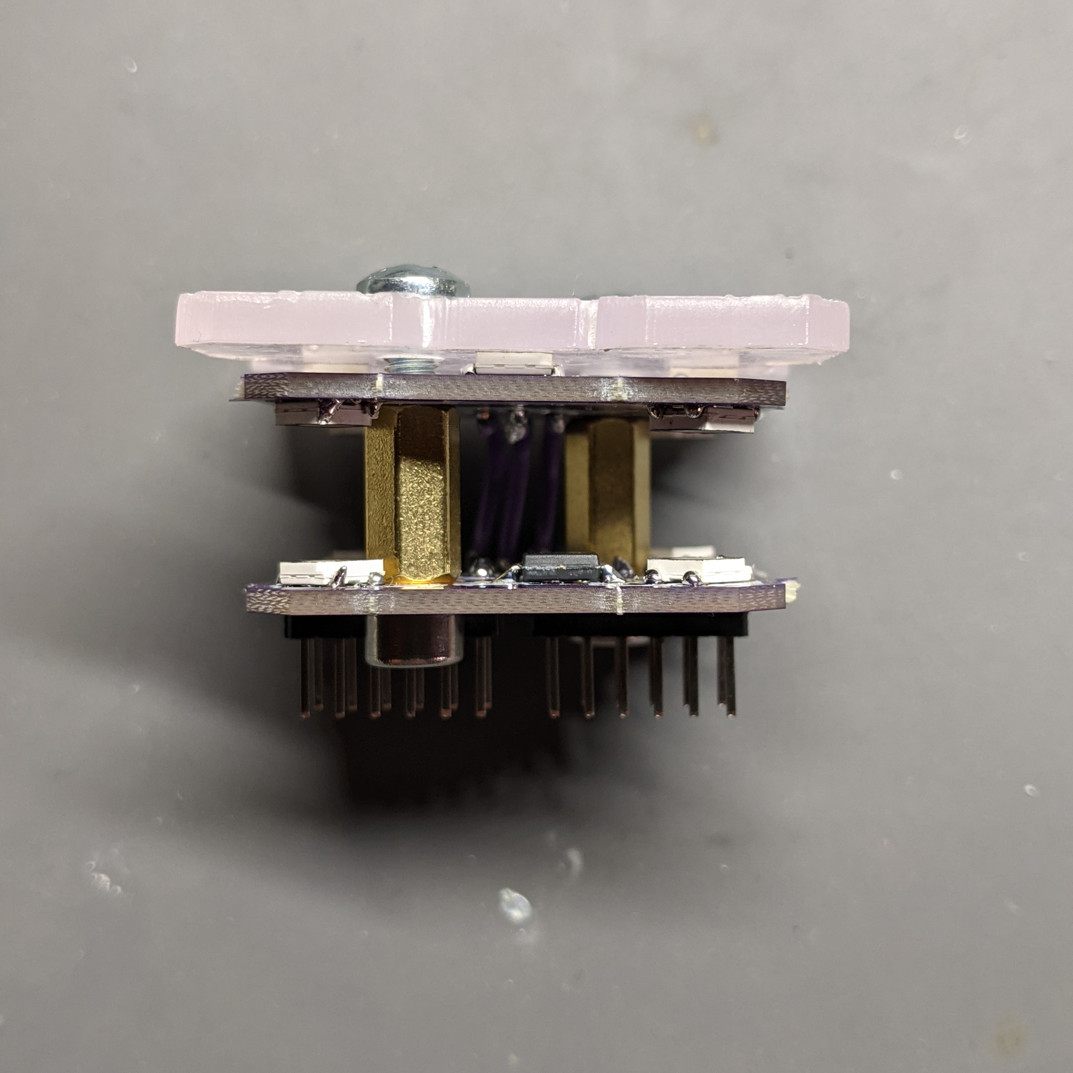
- Attach the stand offs to the base pcb with the socket cap screws.

Step 13

Step 14
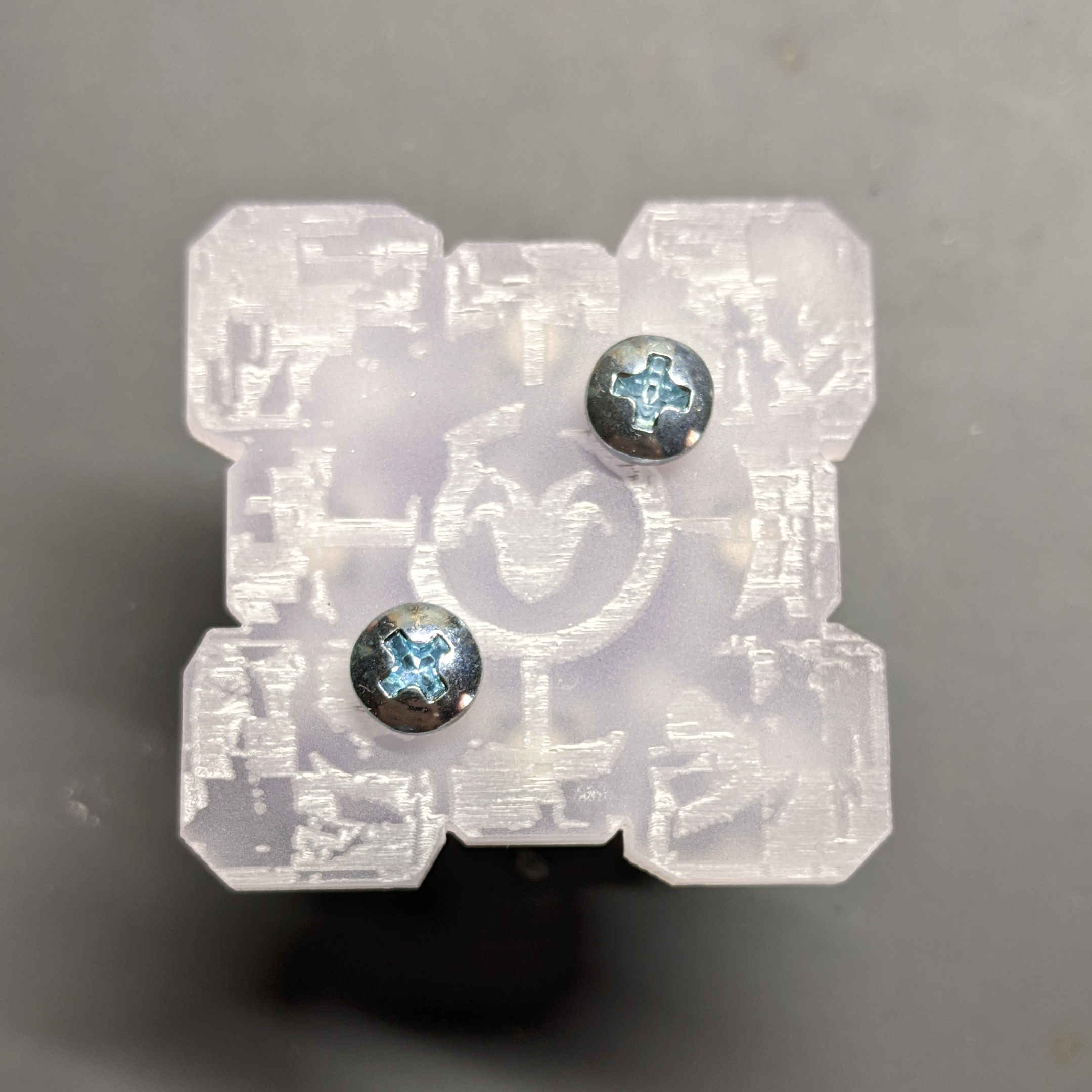
- With the other screws attach the acrylic and the upper pcb to the standoffs.

Step 15

Parts
13| Qty | Value | Footprint | References |
|---|---|---|---|
| 4 | Conn_01x06_Male | Connector_PinHeader_2.54mm:PinHeader_1x06_P2.54mm_Vertical | J1, J2, J3, J4 |
| 4 | WS2812B | customstuff:LED_WS2812B_Minimal | D1, D2, D3, D4 |
| 2 | MountingHole_Pad | MountingHole:MountingHole_4.3mm_M4_DIN965_Pad_TopOnly | H1, H2 |
| 1 | ATtiny85-20SU | Package_SO:SOIJ-8_5.3x5.3mm_P1.27mm | U1 |
| 1 | Conn_01x01_Female | Connector_Wire:SolderWirePad_1x01_SMD_1x2mm | J6 |
| 1 | Conn_01x03_Female | Connector_PinHeader_2.54mm:PinHeader_1x03_P2.54mm_Vertical_SMD_Pin1Left | J5 |
More from mspicer/hitb2022
2- 2 layers34.8 × 34.8 mm

- 2 layers34 × 34 mm

Similar boards
- 2 layers60.3 × 35.3 mm

- 2 layers75 × 82.1 mm

- 2 layers56.4 × 30.4 mm

Nyan
d-haldane/nyan-bow
Select the green Use This Template button towards the top of this page and create a new repository. If you do not see this button, sign into GitHub.
21 parts1BSD-3-Clause - 2 layers73.1 × 87.8 mm

- 2 layers81 × 156.1 mm

- 2 layers

- 2 layers12 × 80 mm

- 2 layers60 × 58.8 mm

Dashcam
TechsDarshan/dashcam_DB
The Dashcam Daughter Board is a sub-board of the Dashcam project. It controls the neopixel indicators, includes a buzzer, and houses a reset button.
28 parts
Questions
How big is the Companion PCB?
It measures 34.8 × 34.8 mm and has 2 copper layers, 1.6 mm thick.
What parts does the Companion use?
13 parts, built around the ATTINY85-20SU and WS2812B. The full list of its parts is on this page, with links to each part's symbol and footprint where PCBKit's library has them.
Where can I download the Companion KiCad files?
From the mspicer/hitb2022 repository on GitHub, at the commit this page was made from: the board is kicad-files/base-pcb/companion.kicad_pcb and its schematic kicad-files/base-pcb/companion.kicad_sch. PCBKit opens the board in the browser, with nothing to install.
Can I use the Companion design in my own project?
Its repository states no licence, so its author keeps all rights: ask mspicer before reusing the design.