4 layers91.3 × 53.5 mm
Ssd2828 board
dartcom/ssd2828-dev
A carrier board for the ssd2828 and the LH154Q01 & VS035ZSM lcd panels
144 parts23

 MSF-Telecom/UT-GPS
A small, internal, and open-source GPS module for ICOM IC-5060 and IC-6060 radios.
KiCAD ICOM Internal GPS is an open-source printed circuit board by MSF-Telecom, from the MSF-Telecom/UT-GPS repository on GitHub, published under the CC-BY-SA-4.0 licence. It is a 2-layer board of 20 × 35 mm with 30 parts on 58 nets, routed with 15,269 tracks and 72 vias.
It is built around the MAX-M10M-00B, XL-3216UOC and KPTR-3216SURCK, with the RB551V-40 and XL-3216SURC among its other parts. Its parts include 10 resistors, 6 capacitors, 5 diodes, 3 connectors and 2 ICs. It belongs with the radio and wireless boards of this library.


A small, internal, and open-source GPS module for ICOM IC-5060 and IC-6060 radios.
The UT-GPS module is a small, internal, and open-source GPS module for ICOM IC-5060 and IC-6060 radios. It is designed to fit in the internal expansion port, with the same form factor as the ICOM UT-126H digital module, and provide a UART NMEA GPS module with 4800/9600 baud rate. The module is designed to be compatible with a 5V supply, and provide a 5V antenna supply. The module has a UFL antenna connector, and test pads for VCC, GND, TX, RX and PPS.
This module was created to replace existing external GPS modules which are often out of stock, soon to be end of life, expensive, and only compatible with GPS satellites. The UT-GPS module is designed to be compatible with GPS, GLONASS, Galileo, and Beidou satellites, and provide more reliable position data.
The first revision uses the u-blox MAX-M10 GPS module, and omits battery backup to facilitate shipping (no lithium batteries).
It was first tested on terrain in Burundi, with 10 hand-assembled prototypes; after validating those prototypes 50 assembled units were ordered from Aisler, 35 of which have been deployed in Central African Republic.
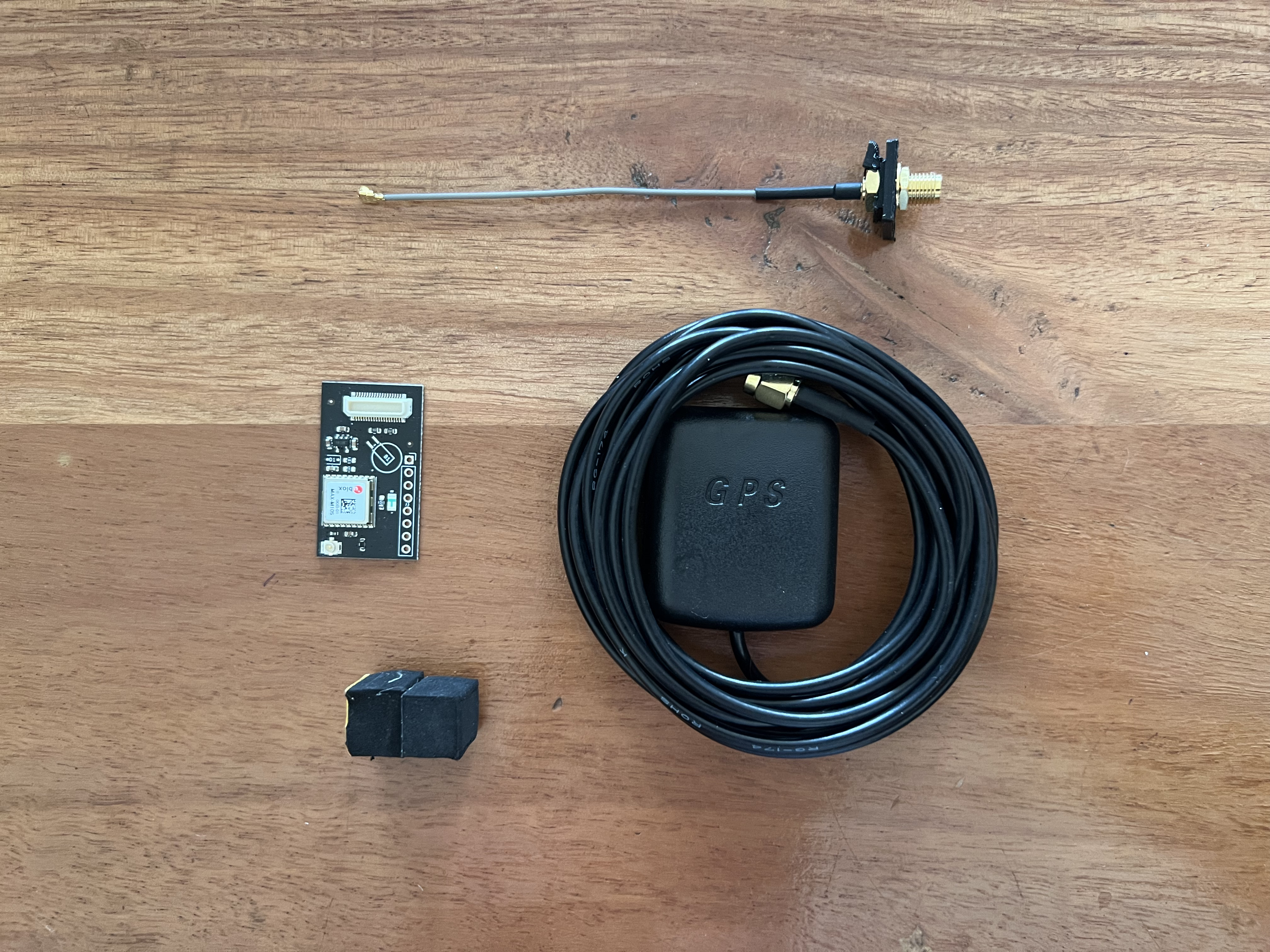
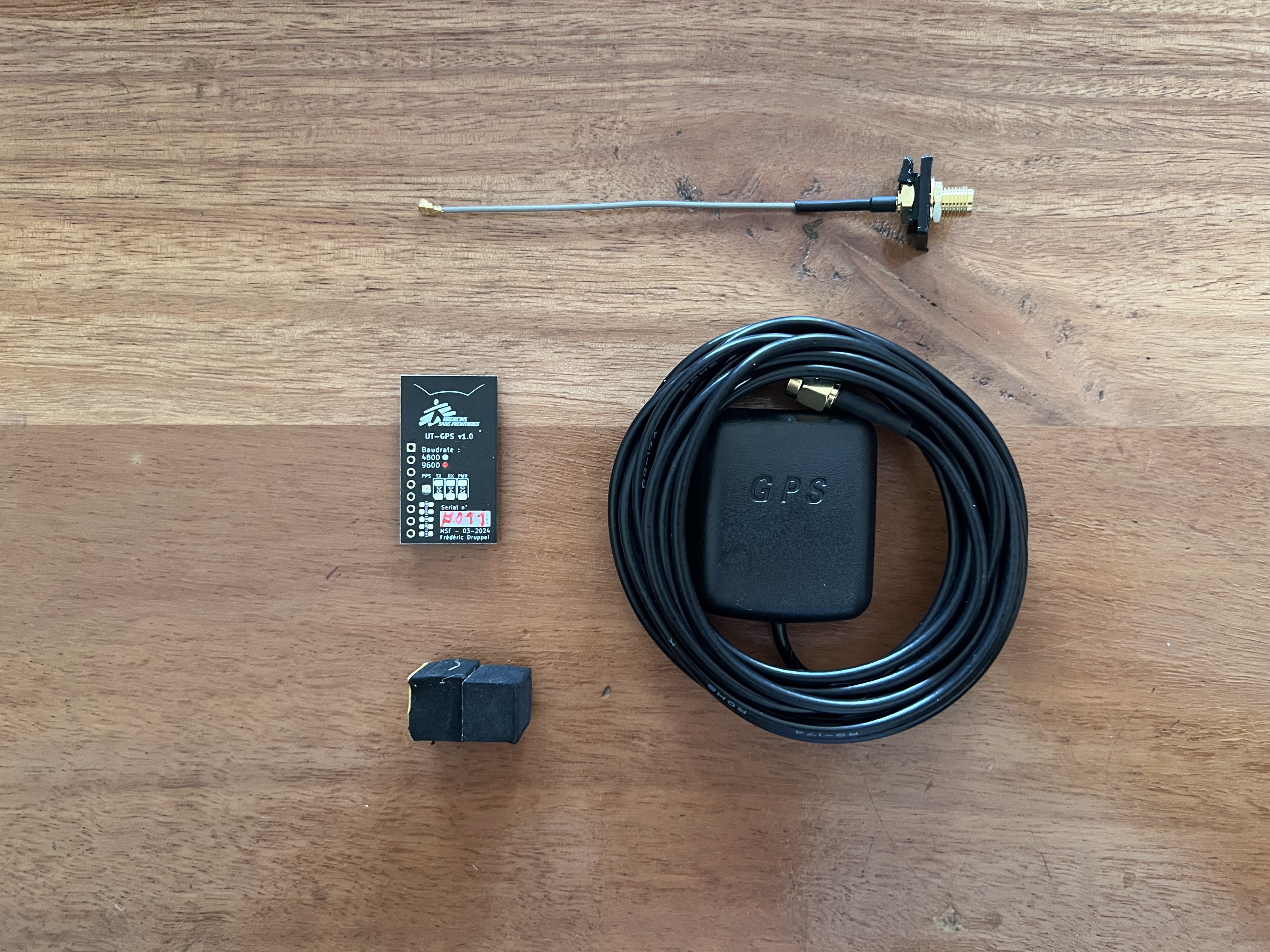
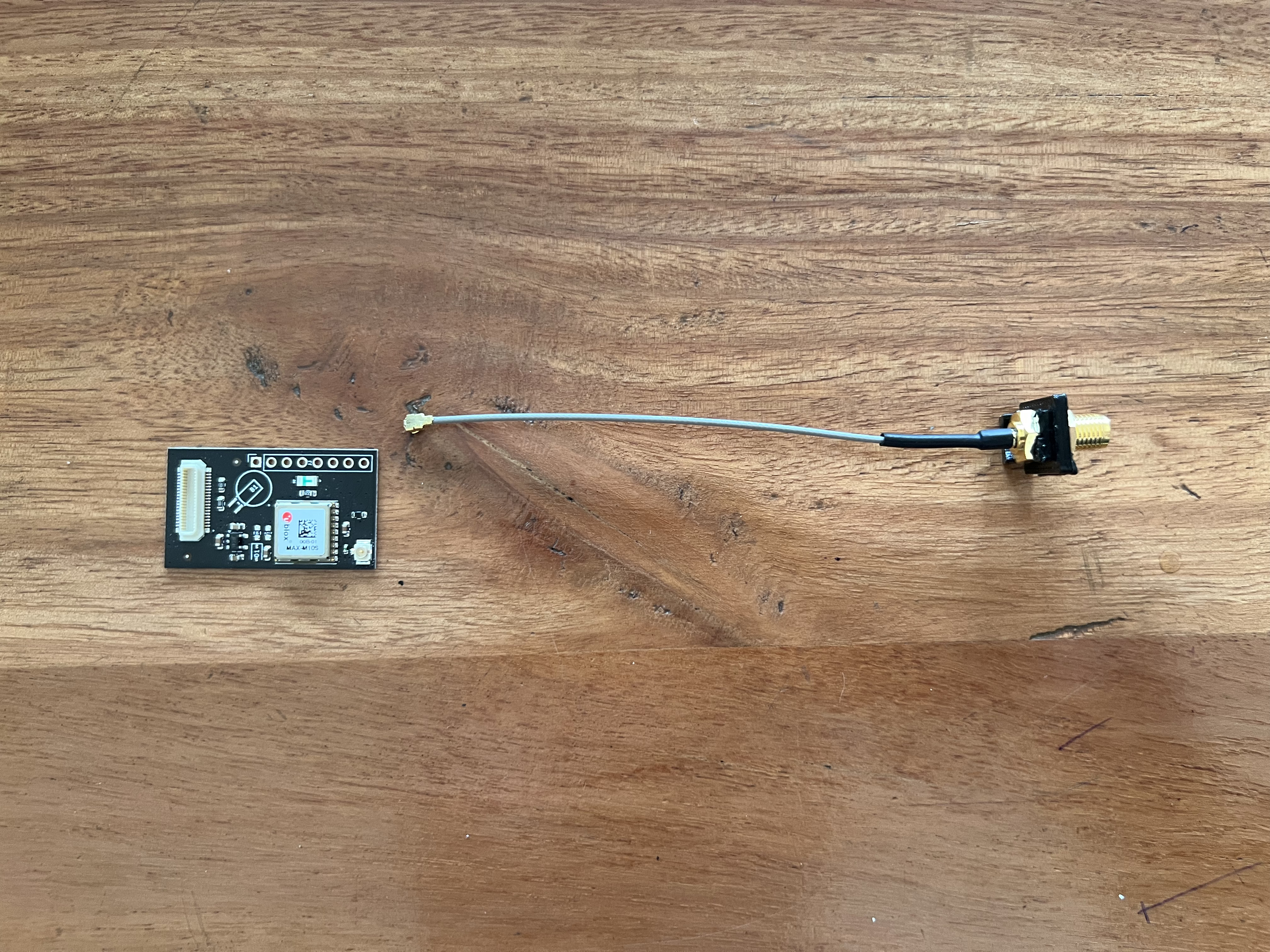
The kit contains the following items (top to bottom, left to right) :
Refer to the installer/mechanic/radio operator who installed the radio for exact steps to remove the radio from the vehicle.
If an existing GPS module is present, remove it from the vehicle.
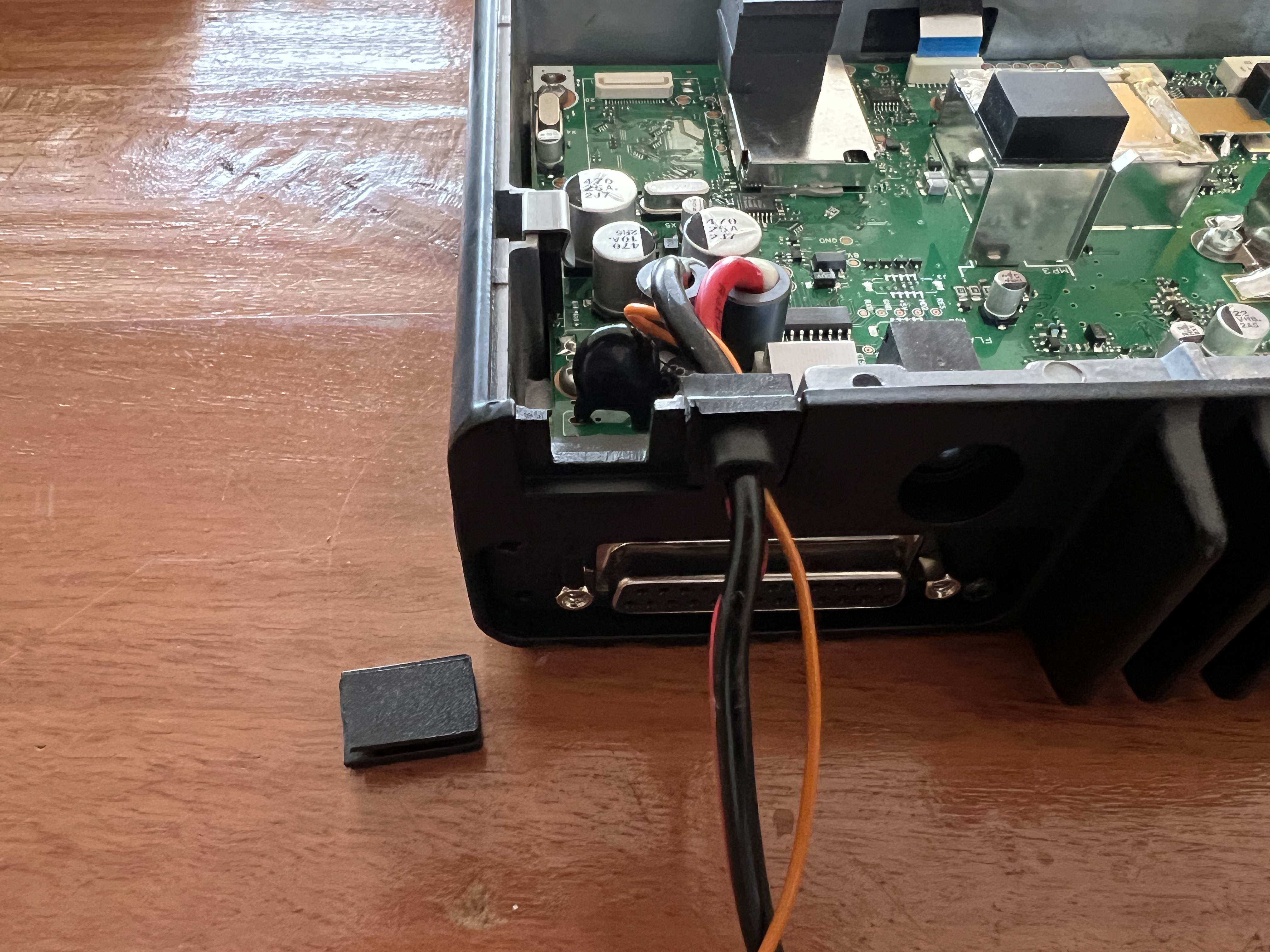
Remove the 4 screws holding the bottom cover of the radio.
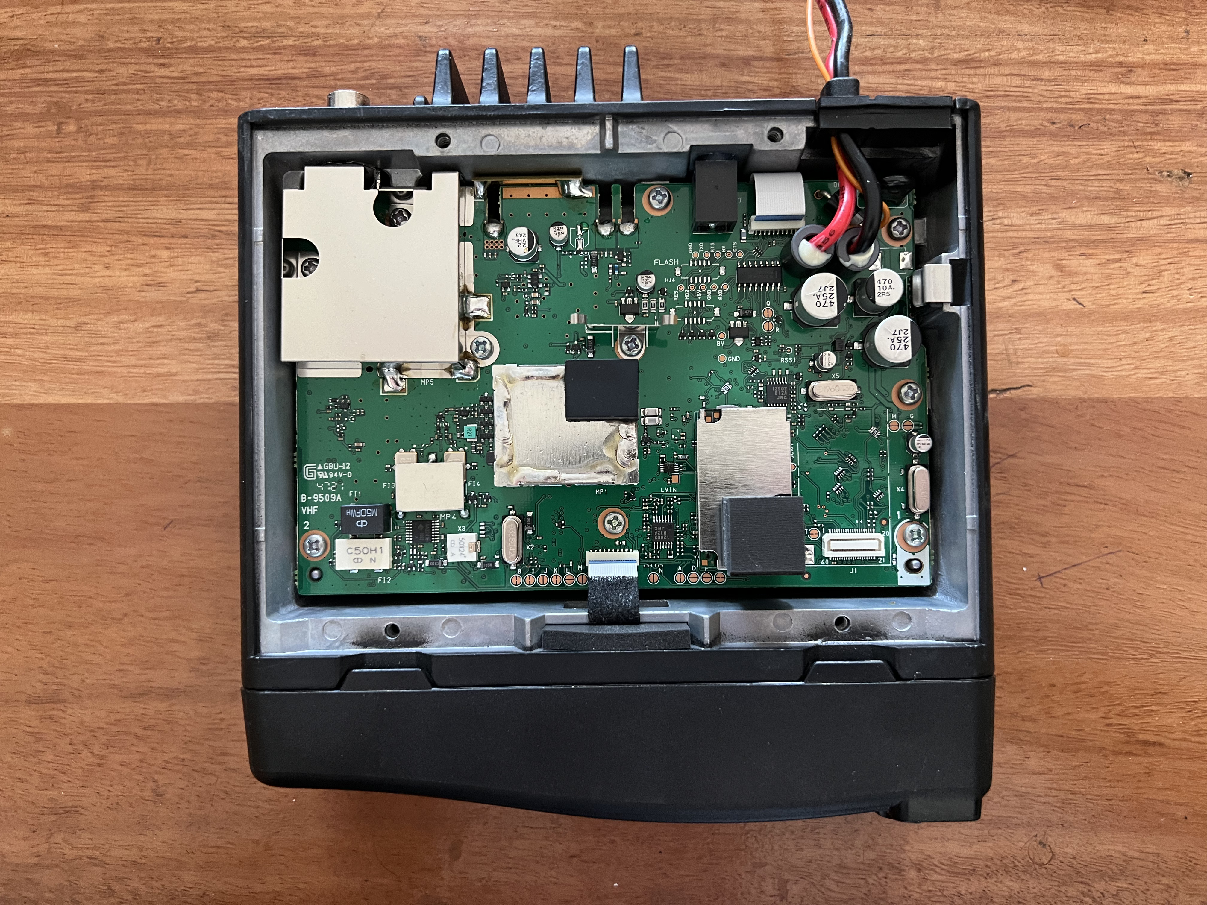
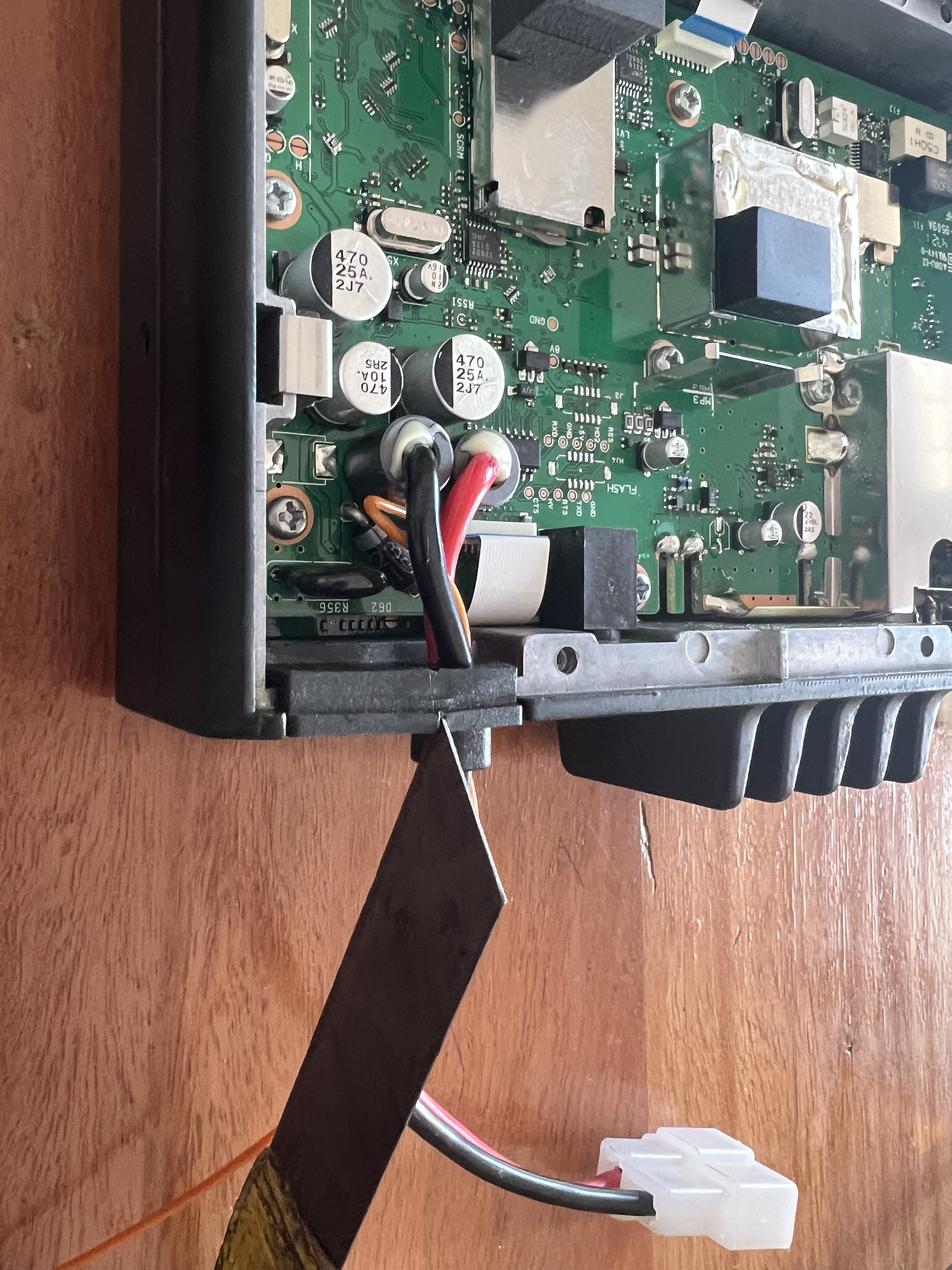
Note : be careful not to cut the power cables.
Once removed you should have a hole that looks like this :
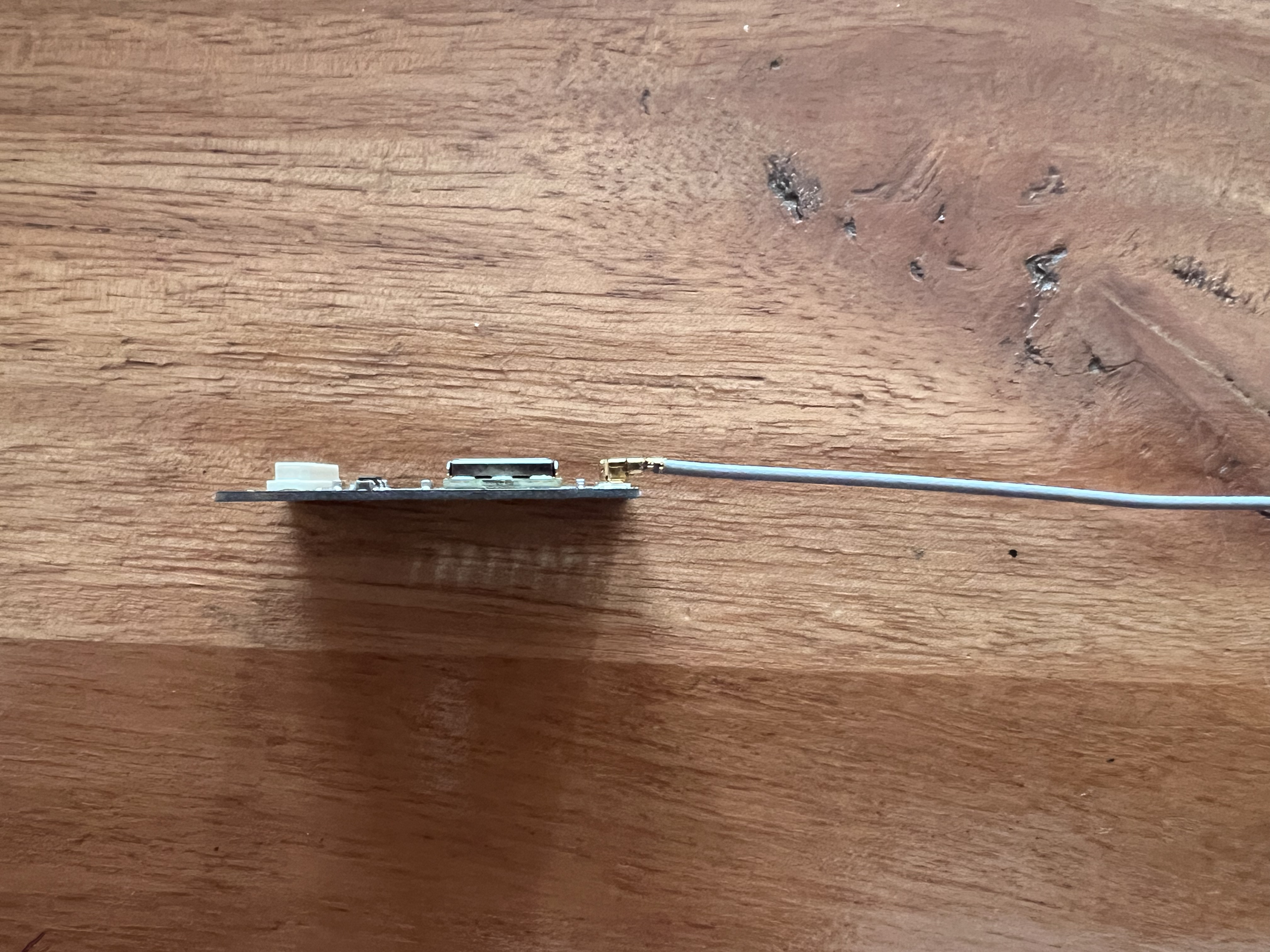
The U.FL to SMA cable should be connected to the U.FL connector on the UT-GPS module.
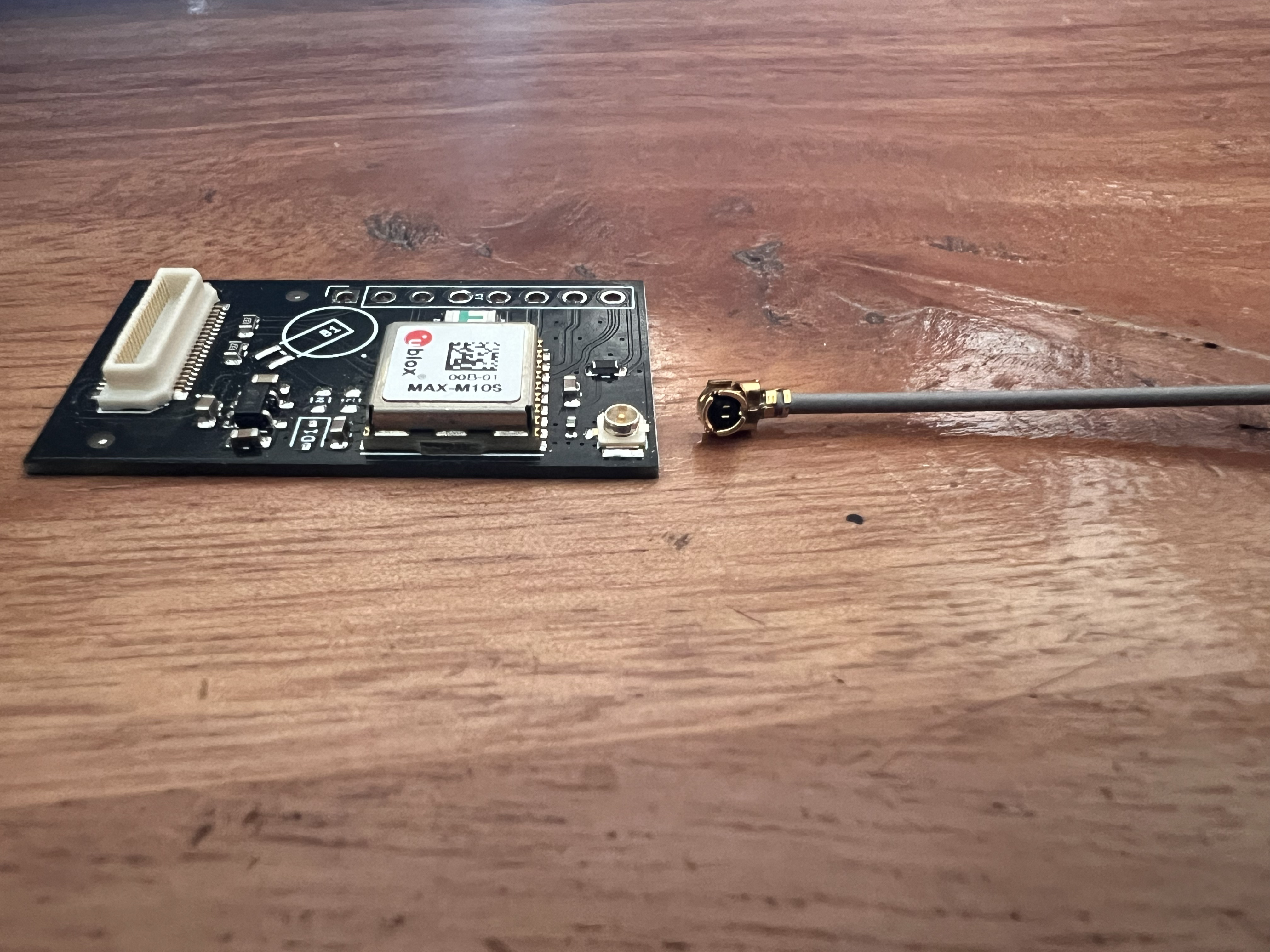
Once connected, the assembly should look like this :
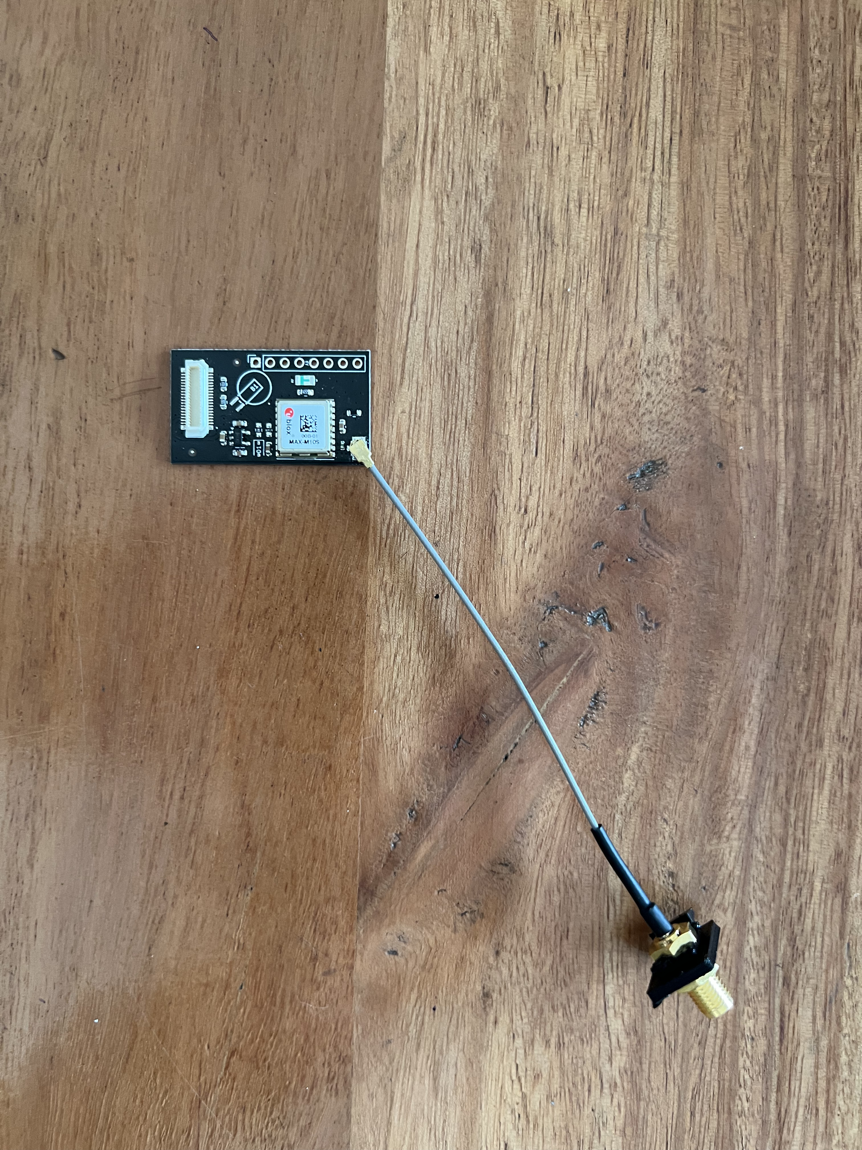
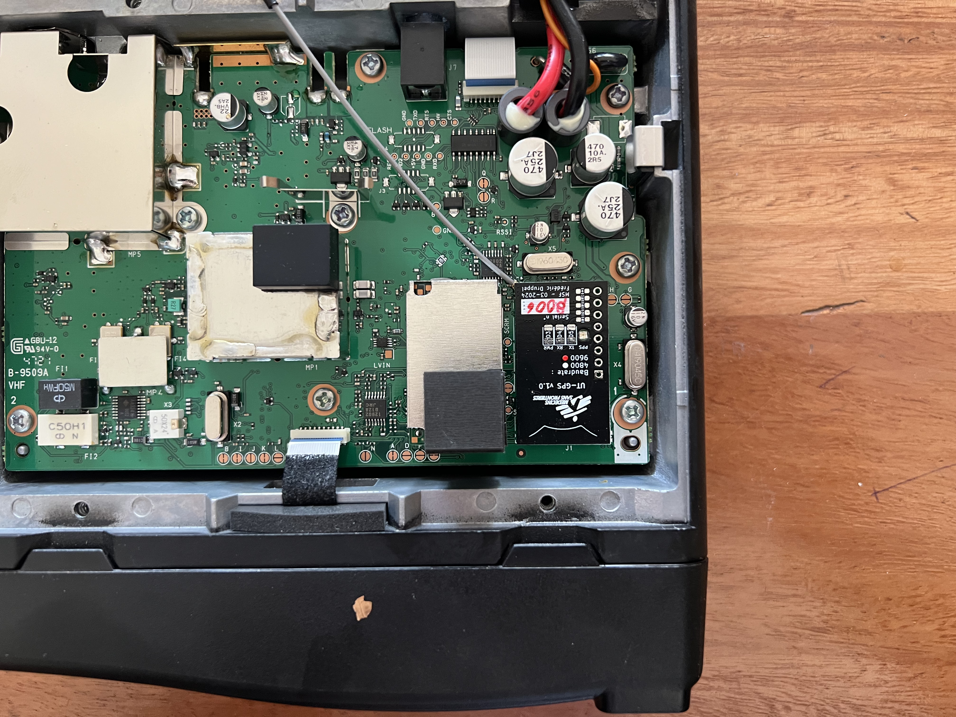
The UT-GPS module should be inserted in the expansion port, with the U.FL connector facing the back of the radio.
Note : Be careful while connecting the UT-GPS, as the expansion port is fragile.
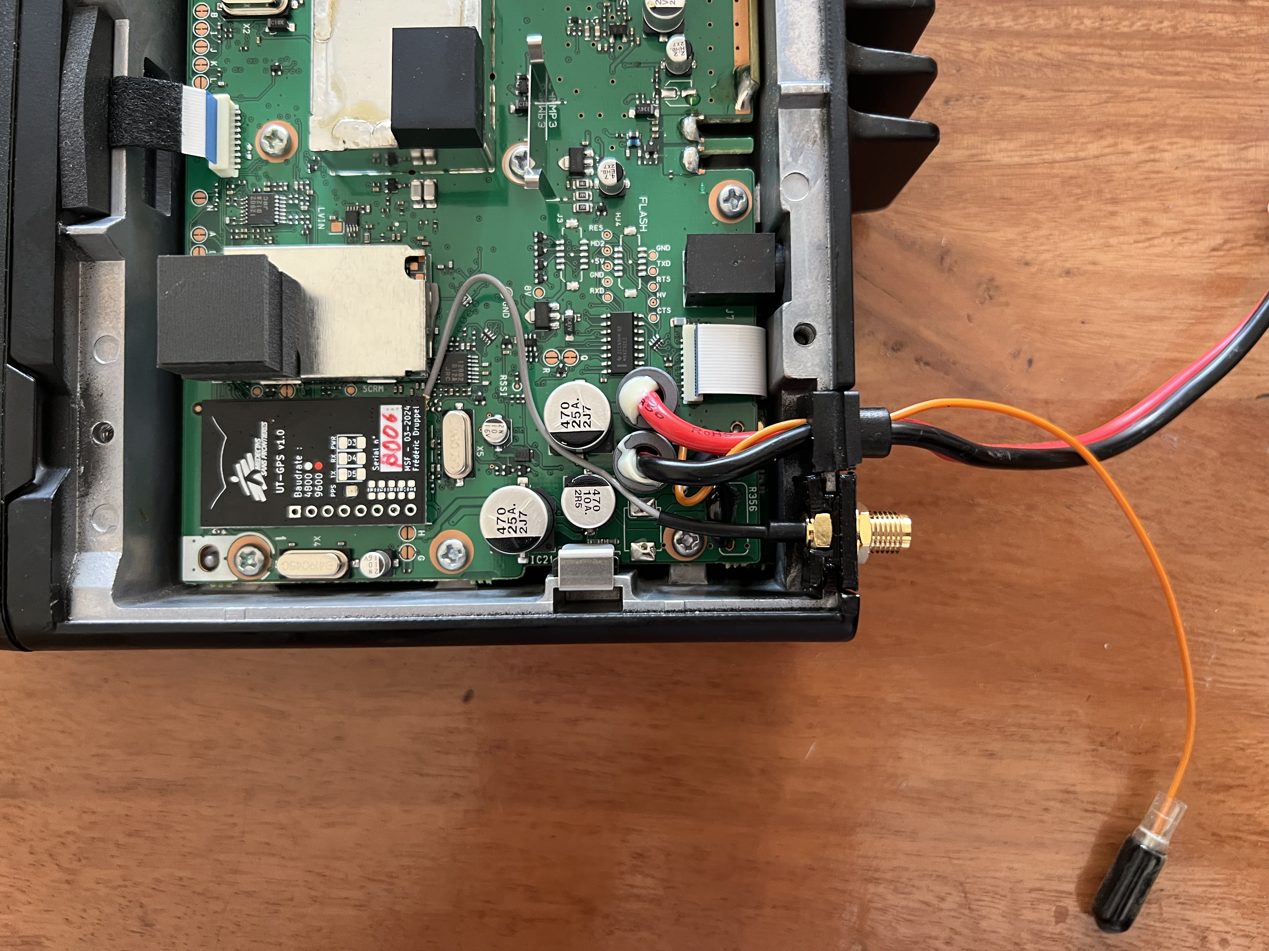
Be careful to route the coaxial cable correctly, and not to pinch it.
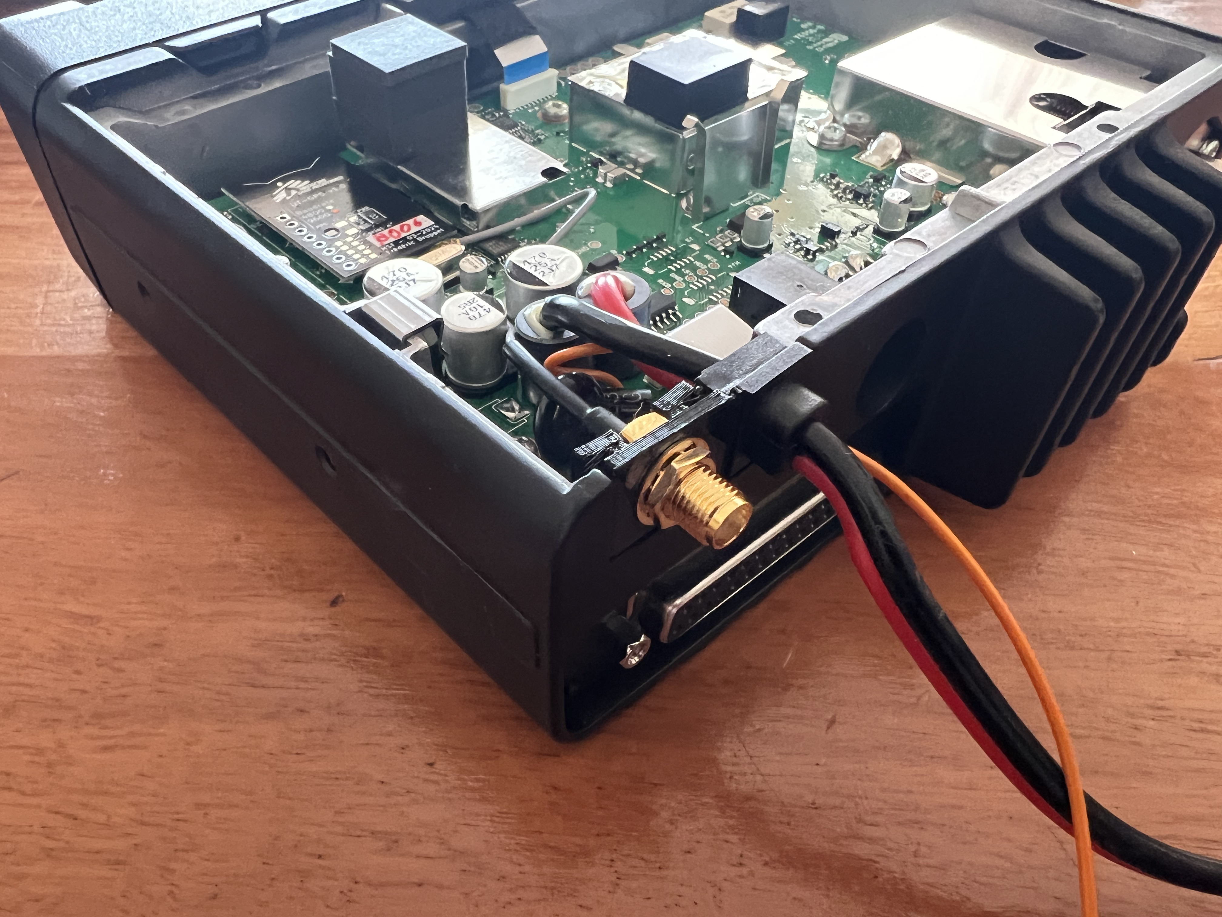
The foam pad should be placed on top of the module over the MSF logo. This will prevent the module from moving around and disconnecting in the radio due to vehicle vibrations.
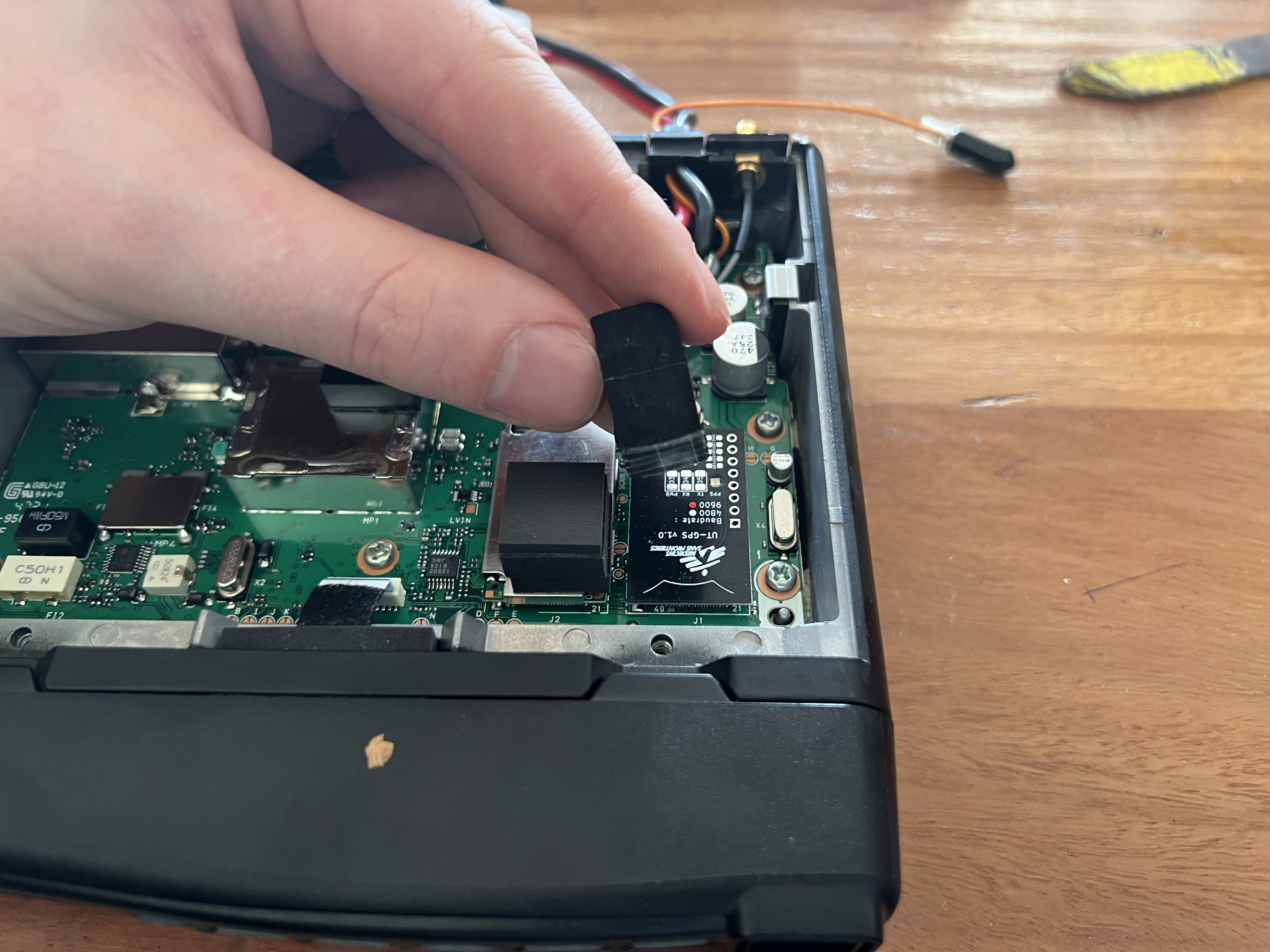
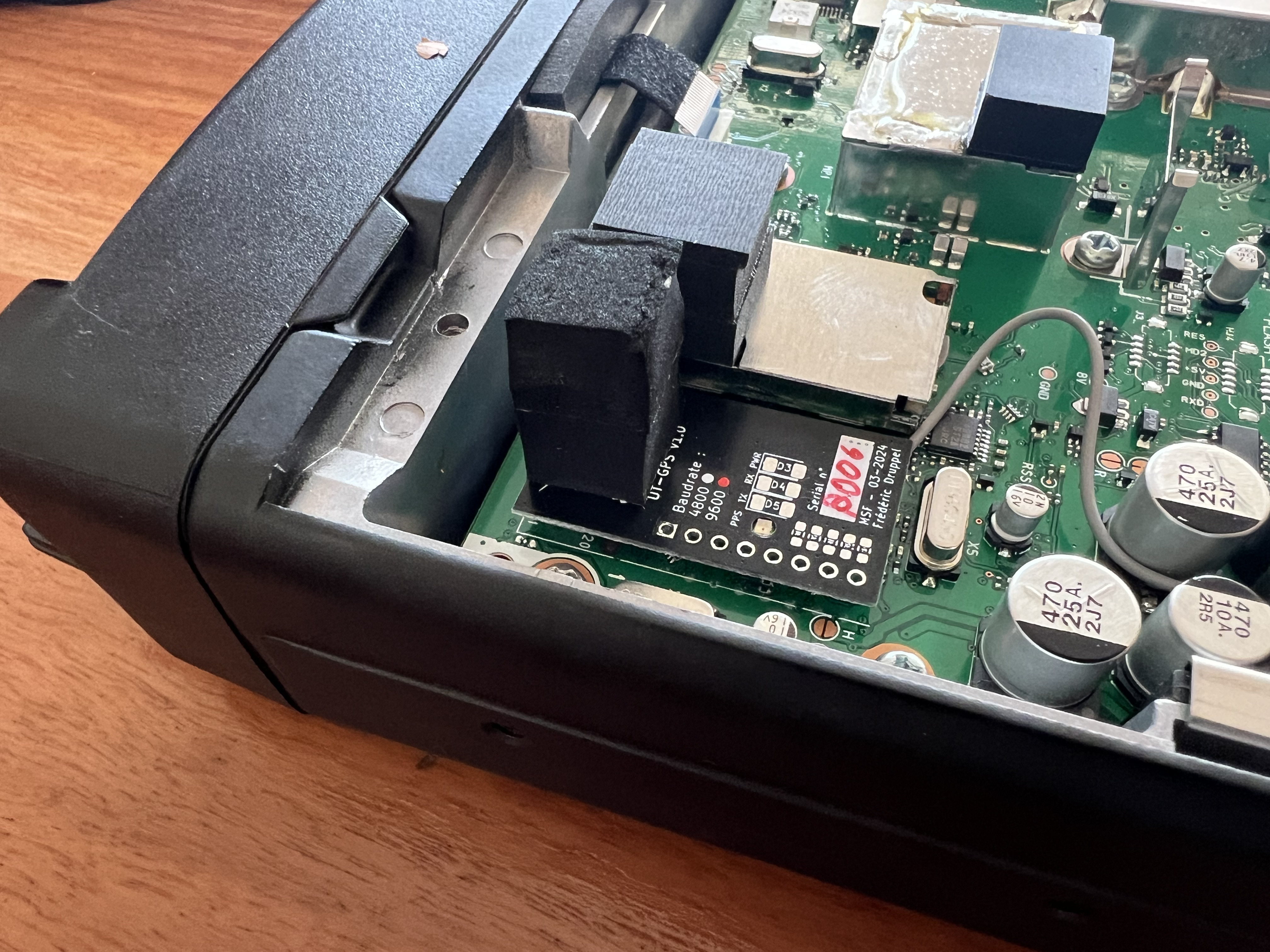
Put the cover back on the radio, and screw it back in place.
The radio should be flashed with a new profile that includes the GPS module on the internal connector at 9600 baud.
This profile should be available to the radio operator who installed the radio.
To confirm the module is working, connect an external GPS antenna to the SMA connector.
Note : The antenna should be outside facing the sky, and have a clear view of the sky.
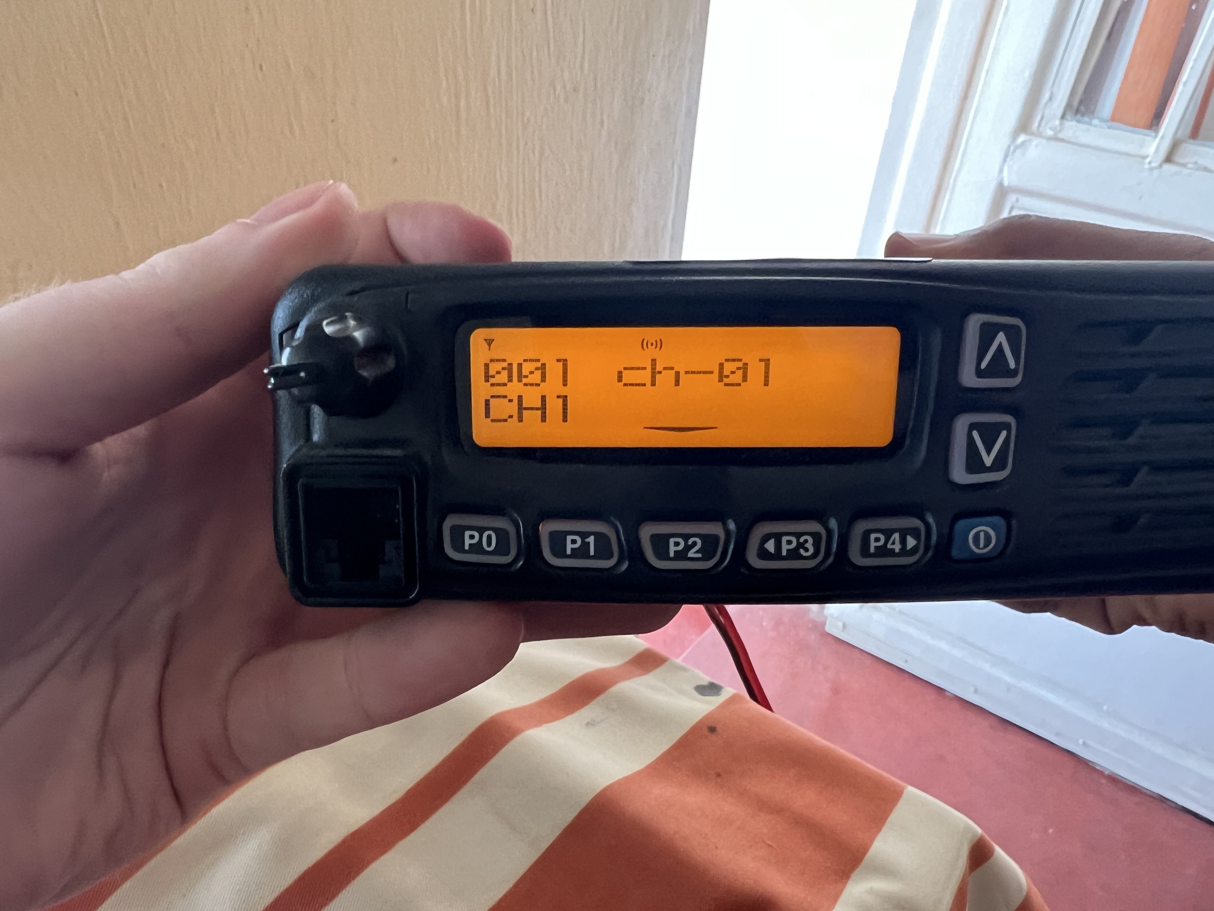
The GPS signal icon should be visible on the radio display (top center).
The antenna can be installed on the roof of the vehicle, or on the dashboard behind the windshield. The antenna should have a clear view of the sky.
If an existing GPS module was present, the new GPS antenna can be put in its place.
Note : be careful tot to pinch the coaxial cable, and to route it to the back of the radio mounting location.
Note : only use the provided SMA antenna.
Refer to the installer/mechanic/radio operator who installed the radio for exact steps to reinstall the radio in the vehicle.
Turn on the radio, and check the GPS status. The GPS status should be visible on the radio display.
The same icon as in step 8 should be visible on the radio display.
A. Must have
B. Nice to have
C. Optional
Cost for one unit at 100pcs MOQ, without PCBA
| Component | Source | Cost ($) | Amount | Total ($) |
|---|---|---|---|---|
| PCB | JLCPCB | 0.141 | 1 | 0.141 |
| LQG15HS27NJ02DLQG15HS27NJ02D 27nH inductor | LCSC | 0.0065 | 1 | 0.0065 |
| U.FL-R-SMT-1(10) UFL connector | LCSC | 0.0.1177 | 1 | 0.1615 |
| SPX5205M5-L-3-3/TR 3.3V LDO regulator | LCSC | 0.1209 | 1 | 0.1209 |
| 0603B105K250NT 1uF 25V capacitor | LCSC | 0.0053 | 2 | 0.0106 |
| CC0603KRX7R0BB103 10nF 16V capacitor | LCSC | 0.0041 | 4 | 0.0164 |
| RC0603JR-07220RL 220 Ohm resistor | LCSC | 0.001 | 4 | 0.0040 |
| CR0603-FX-3301ELF 3.3k Ohm resistor | LCSC | 0.0062 | 3 | 0.0186 |
| ERJPA3J100V 10 Ohm resistor | LCSC | 0.0193 | 1 | 0.0193 |
| APTR3216SURCK Through-PCB LED | LCSC | 0.1032 | 1 | 0.1032 |
| MAX-M10S-00B GPS module | Mouser | 11.48 | 1 | 11.48 |
| AXK640347YG Connector | Mouser | 1.60 | 1 | 1.60 |
| MS518SE-FL35E Battery | Farnell | 2.15 | 1 | 2.15 |
| RB551V-40 Diode | LCSC | 0.018 | 1 | 0.018 |
| XL-3216SURC Red LED | LCSC | 0.0082 | 1 | 0.0082 |
| XL-3216UOC Orange LED | LCSC | 0.0092 | 2 | 0.0184 |
| Total | 15.8766 |
| Component | Source | Cost ($) | Amount | Total ($) |
|---|---|---|---|---|
| PCB | JLCPCB | 0.141 | 1 | 0.141 |
| LQG15HS27NJ02DLQG15HS27NJ02D 27nH inductor | LCSC | 0.0065 | 1 | 0.0065 |
| U.FL-R-SMT-1(10) UFL connector | LCSC | 0.0.1177 | 1 | 0.1615 |
| SPX5205M5-L-3-3/TR 3.3V LDO regulator | LCSC | 0.1209 | 1 | 0.1209 |
| 0603B105K250NT 1uF 25V capacitor | LCSC | 0.0053 | 2 | 0.0106 |
| CC0603KRX7R0BB103 10nF 16V capacitor | LCSC | 0.0041 | 4 | 0.0164 |
| RC0603JR-07220RL 220 Ohm resistor | LCSC | 0.001 | 1 | 0.0010 |
| CR0603-FX-3301ELF 3.3k Ohm resistor | LCSC | 0.0062 | 3 | 0.0186 |
| ERJPA3J100V 10 Ohm resistor | LCSC | 0.0193 | 1 | 0.0193 |
| APTR3216SURCK Through-PCB LED | LCSC | 0.1032 | 1 | 0.1032 |
| MAX-M10S-00B GPS module | Mouser | 11.48 | 1 | 11.48 |
| AXK640347YG Connector | Mouser | 1.60 | 1 | 1.60 |
| MS518SE-FL35E Battery | Farnell | 2.15 | 1 | 2.15 |
| RB551V-40 Diode | LCSC | 0.018 | 1 | 0.018 |
| Total | 15.847 |
| Component | Source | Cost ($) | Amount | Total ($) |
|---|---|---|---|---|
| PCB | JLCPCB | 0.141 | 1 | 0.141 |
| LQG15HS27NJ02DLQG15HS27NJ02D 27nH inductor | LCSC | 0.0065 | 1 | 0.0065 |
| U.FL-R-SMT-1(10) UFL connector | LCSC | 0.0.1177 | 1 | 0.1615 |
| SPX5205M5-L-3-3/TR 3.3V LDO regulator | LCSC | 0.1209 | 1 | 0.1209 |
| 0603B105K250NT 1uF 25V capacitor | LCSC | 0.0053 | 2 | 0.0106 |
| CC0603KRX7R0BB103 10nF 16V capacitor | LCSC | 0.0041 | 3 | 0.0164 |
| RC0603JR-07220RL 220 Ohm resistor | LCSC | 0.001 | 1 | 0.0010 |
| CR0603-FX-3301ELF 3.3k Ohm resistor | LCSC | 0.0062 | 2 | 0.0186 |
| ERJPA3J100V 10 Ohm resistor | LCSC | 0.0193 | 1 | 0.0193 |
| APTR3216SURCK Through-PCB LED | LCSC | 0.1032 | 1 | 0.1032 |
| MAX-M10S-00B GPS module | Mouser | 11.48 | 1 | 11.48 |
| AXK640347YG Connector | Mouser | 1.60 | 1 | 1.60 |
| Total | 13.6687 |
Made with ❤️, lots of ☕️, and lack of 🛌
Published under CreativeCommons BY-SA 4.0

This work is licensed under a Creative Commons Attribution-ShareAlike 4.0 International License.
| Qty | Value | Footprint | References |
|---|---|---|---|
| 4 | 10nF | Capacitor_SMD:C_0603_1608Metric | C3, C4, C5, C6 |
| 4 | 220 | Resistor_SMD:R_0603_1608Metric_Pad0.98x0.95mm_HandSolder | R5, R6, R7, R8 |
| 3 | 3.3k | Resistor_SMD:R_0603_1608Metric | R2, R3, R4 |
| 2 | 1uF | Capacitor_SMD:C_0603_1608Metric | C1, C2 |
| 2 | 3.3k | Resistor_SMD:R_0603_1608Metric_Pad0.98x0.95mm_HandSolder | R9, R10 |
| 2 | Fiducial_0.5mm_Mask1.5mm | Fiducial:Fiducial_0.5mm_Mask1.5mm | F1, F2 |
| 2 | XL-3216UOC | LED_SMD:LED_1206_3216Metric | D4, D5 |
| 1 | 10 | Resistor_SMD:R_0603_1608Metric | R1 |
| 1 | 27nH | Inductor_SMD:L_0402_1005Metric | L1 |
| 1 | Conn_01x08 | Connector_PinSocket_2.54mm:PinSocket_1x08_P2.54mm_Vertical | J3 |
| 1 | ICOM-J1 | ICOM-J1-J2:ICOM-J1-J2 | J1 |
| 1 | KPTR-3216SURCK | KINGBRIGHT KPTR-3216SURCK:LED320X125X130N | D2 |
| 1 | MAX-M10M-00B | MAX-M10S-FP:MOD18_MAX-M10M_UBL | U1 |
| 1 | MS518SE | MS518SE:MS518SE-FL35E | B1 |
| 1 | RB551V-40 | Diode_SMD:D_SOD-323 | D1 |
| 1 | SPX5205 | Package_TO_SOT_SMD:SOT-23-5 | U2 |
| 1 | U.FL-R-SMT-1_10_ | U.FL-R-SMT-1_10:HRS_U.FL-R-SMT-1_10_ | J2 |
| 1 | XL-3216SURC | LED_SMD:LED_1206_3216Metric | D3 |
It measures 20 × 35 mm and has 2 copper layers, 0.8 mm thick.
30 parts, built around the MAX-M10M-00B, XL-3216UOC, KPTR-3216SURCK and RB551V-40. The full list of its parts is on this page, with links to each part's symbol and footprint where PCBKit's library has them.
From the MSF-Telecom/UT-GPS repository on GitHub, at the commit this page was made from: the board is hardware/KiCAD-ICOM-Internal-GPS/KiCAD-ICOM-Internal-GPS.kicad_pcb and its schematic hardware/KiCAD-ICOM-Internal-GPS/KiCAD-ICOM-Internal-GPS.kicad_sch. PCBKit opens the board in the browser, with nothing to install.
Its repository publishes it under the CC-BY-SA-4.0 licence: you may reuse it on that licence's terms (keep the author's notice, and for a copyleft licence share your changes alike).
dartcom/ssd2828-dev
A carrier board for the ssd2828 and the LH154Q01 & VS035ZSM lcd panels


itsmevjnk/MelbourneTrainTracker
Melbourne Train Tracker project repository (SIT210, T1/2025)

ThunderFly-aerospace/TFRPM01
Revolutions per minute (RPM) meter for UAV, rotors, wheels and engines.

eggsworks/le-oeuf-v2
An ultra-low profile (Kailh PG1316S) keyboard inspired by Le Chiffre.

FPGA-Research/FABulous_board
A PCB created for FABulous FPGAs, based on the caravel board.

ThunderFly-aerospace/TFUNIPAYLOAD01
Universal interface for TF-ATMON sensor payload.

Ash-tronix/nile_test_chip_pcb
KiCad PCB design files to support the Ashtronix® Nile test chip.