2 layers20.3 × 69.7 mm
PG attiny404
fabiansteiner/OpenValve
3D-printable pinch valve for irrigation and sensor-driven liquid control.
41 parts276CERN-OHL-S-2.0
 mschneider-git/zigbee-roller-shutter
Zigbee retrofit for a Heim & Haus solar roller shutter: ESP32-H2 sleepy end device firmware (ESP-IDF) and carrier PCB, for Home Assistant ZHA
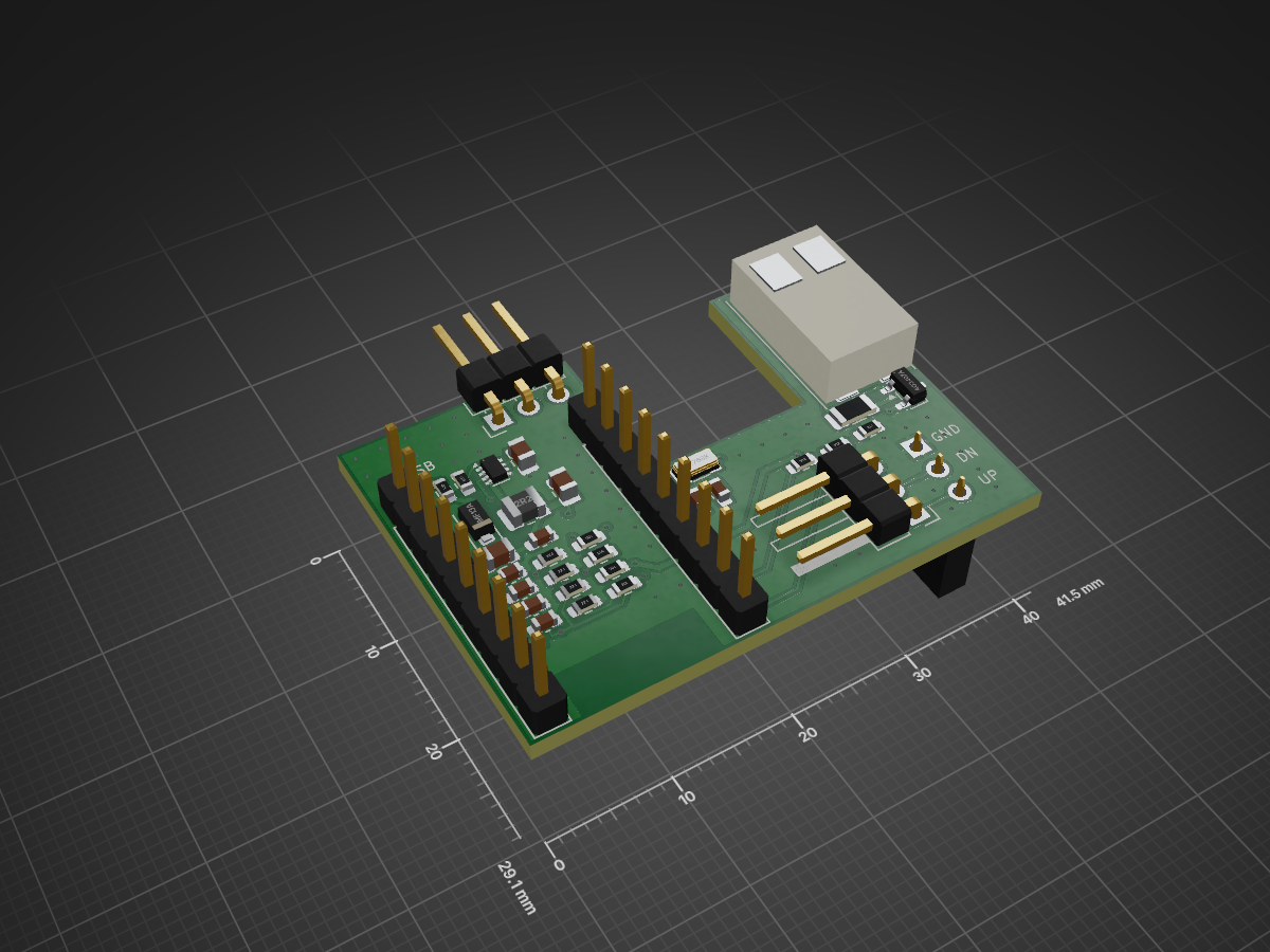
Roller carrier is an open-source printed circuit board by mschneider-git, from the mschneider-git/zigbee-roller-shutter repository on GitHub, published under the MIT licence. It is a 2-layer board of 41.5 × 29.1 mm with 35 parts on 22 nets, routed with 219 tracks and 73 vias.
It is built around the AO3407A and SMF13A. Its parts include 13 resistors, 10 capacitors, 6 connectors, 1 IC and 1 diode. It belongs with the power boards of this library.


2-layer board (41.5 × 29.1 mm, U-shaped) that plugs directly onto the 3-pin keypad header of the original controller board. A Waveshare ESP32-H2-Zero sits on spacers above the regulator and dividers and is soldered in by hand; JLCPCB can assemble everything else.
| Top | Bottom |
|---|---|
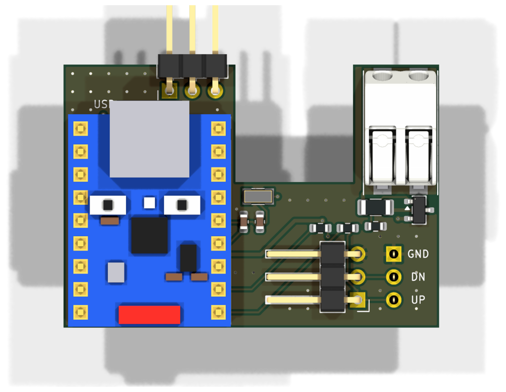 | 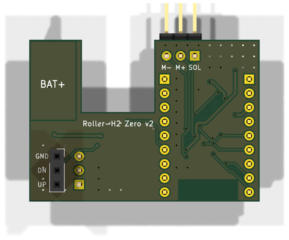 |
The H2-Zero in the renders is a simplified model generated by ../lib/make_footprints.py
from the product photos. For J1 the renders use WAGO's 3D model of the 2060-452/998-404 (from
WAGO's CAD download, not included here because of its terms of use); the board itself references
a simplified model of the terminal from the same script.
| Ref | What | Position |
|---|---|---|
| J6 / J7 | 1×9 holes for the H2-Zero (soldered by hand), USB-C up, antenna down | left |
| J3 | 1×3 socket, bottom side, onto the original keypad header (GND · DOWN · UP) | bottom right |
| J4 | 1×3 header, 90°, membrane keypad, pins towards the board centre, GND on top | bottom right |
| J1 | WAGO 2060-452, battery+ looped through: cut the red battery wire and put both ends into the two spring terminals | right arm, wire entry at the top |
| J5 | 1×3 header, 90°, measurement inputs SOL · M+ · M− (labels on the bottom side), optional, see below | left arm, pins pointing up |
USB-C, BOOT and RESET are on the H2-Zero itself.
USB-C, ESD protection, BOOT/RESET and the EN circuit are on the H2-Zero.
Matches the firmware defaults:
| Signal | GPIO | Row / pin |
|---|---|---|
| Battery (divider) | IO4 | J6 / 8 |
| Motor+ (divider) | IO5 | J6 / 9 |
| Motor− (divider) | IO1 | J6 / 5 |
| Solar (divider) | IO2 | J6 / 6 |
| UP key | IO10 | J7 / 9 |
| DOWN key | IO11 | J7 / 8 |
| 32 kHz crystal | IO13 / IO14 | J7 / 6, 5 |
| 3V3 / GND | – | J6 / 3, 2 |
The H2-Zero is soldered directly into J6/J7 with its pin headers. The plastic strip of the header (about 2.5 mm) acts as spacer: the regulator and dividers sit below it, the tallest part is the inductor L1 at 1.2 mm.
python3 make_board.py                         # placement, nets, silkscreen
python3 route.py /path/to/freerouting.jar     # Freerouting, GND areas, DRC (up to 5 attempts)
python3 ../fab.py carrier                     # fab/gerber.zip, bom_jlc.csv, cpl_jlc.csv
route.py always starts from a fresh make_board.py. Freerouting (2.x, needs Java) does not give
the same result on every run and occasionally hangs; the script checks every attempt with the DRC
and routes again up to five times. A run takes 2–7 minutes.
Expected: 0 DRC errors, 0 unconnected items. The remaining "silk_edge_clearance" warnings are intended (header pins protrude over the edge).
fab/gerber.zip, 2 layers, 1.6 mm.fab/bom_jlc.csv and fab/cpl_jlc.csv.
All parts are regular JLCPCB stock, no Global Sourcing needed. JLCPCB solders the 90° headers
J4 and J5 (C92159) by hand. J3 (8.5 mm socket, C42431866) is in the BOM/CPL but sits on the
bottom side: with "Assembly side: Top", JLCPCB leaves it out (Economic assembles one side only).| Qty | Value | Footprint | References |
|---|---|---|---|
| 5 | 100n | C_0603_1608Metric | C5, C7, C8, C9, C10 |
| 4 | 1M | R_0603_1608Metric | R12, R14, R16, R18 |
| 4 | 220k | R_0603_1608Metric | R13, R15, R17, R19 |
| 2 | 18p | C_0603_1608Metric | C11, C12 |
| 2 | 1k | R_0603_1608Metric | R8, R9 |
| 1 | 10 | R_0603_1608Metric | R1 |
| 1 | 100k | R_0603_1608Metric | R5 |
| 1 | 10u | C_0805_2012Metric | C4 |
| 1 | 10u 25V | C_0805_2012Metric | C1 |
| 1 | 2.2u | L_1008_2520Metric | L1 |
| 1 | 22u | C_0805_2012Metric | C2 |
| 1 | 32.768k | Crystal_SMD_3215-2Pin_3.2x1.5mm | Y1 |
| 1 | 64.9k | R_0603_1608Metric | R2 |
| 1 | AO3407A | SOT-23 | Q1 |
| 1 | H2-Zero soldered left | PinSocket_1x09_P2.54mm_Vertical | J6 |
| 1 | H2-Zero soldered right | PinSocket_1x09_P2.54mm_Vertical | J7 |
| 1 | Membrane keypad | PinHeader_1x03_P2.54mm_Horizontal | J4 |
| 1 | PTC 100mA | Fuse_1206_3216Metric | F1 |
| 1 | SMF13A | D_SOD-123F | D1 |
| 1 | Solar M+ M- | PinHeader_1x03_P2.54mm_Horizontal | J5 |
| 1 | TPS629203DRLR | SOT-583-8 | U1 |
| 1 | WAGO 2060-452 battery+ | footprints:WAGO_2060-452 | J1 |
| 1 | to keypad header | PinSocket_1x03_P2.54mm_Vertical | J3 |
It measures 41.5 × 29.1 mm and has 2 copper layers, 1.6 mm thick.
35 parts, built around the AO3407A and SMF13A. The full list of its parts is on this page, with links to each part's symbol and footprint where PCBKit's library has them.
From the mschneider-git/zigbee-roller-shutter repository on GitHub, at the commit this page was made from: the board is hardware/carrier/roller_carrier.kicad_pcb. PCBKit opens the board in the browser, with nothing to install.
Its repository publishes it under the MIT licence: you may reuse it on that licence's terms (keep the author's notice, and for a copyleft licence share your changes alike).
fabiansteiner/OpenValve
3D-printable pinch valve for irrigation and sensor-driven liquid control.


mamejay/C64-USB-C-PD-Power-Adapter
USB-C PD power adapter for the Commodore 64 (KiCad, JLCPCB-ready)


teapotlaboratories/bwlr1e
Teapotlabs BWLR1E: Wireless Environmental Sensor with Energy Harvesting from Solar Energy