Skip to the content
PCBKitNew board
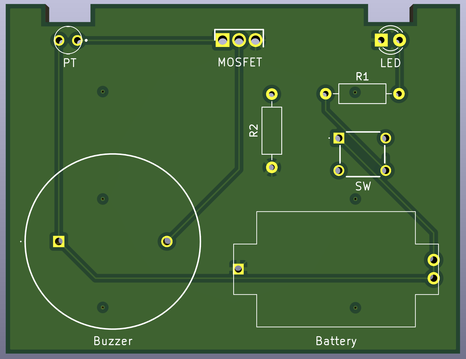
2 layers63 × 48.5 mmLED Morsecode, the printed circuit board in 3D

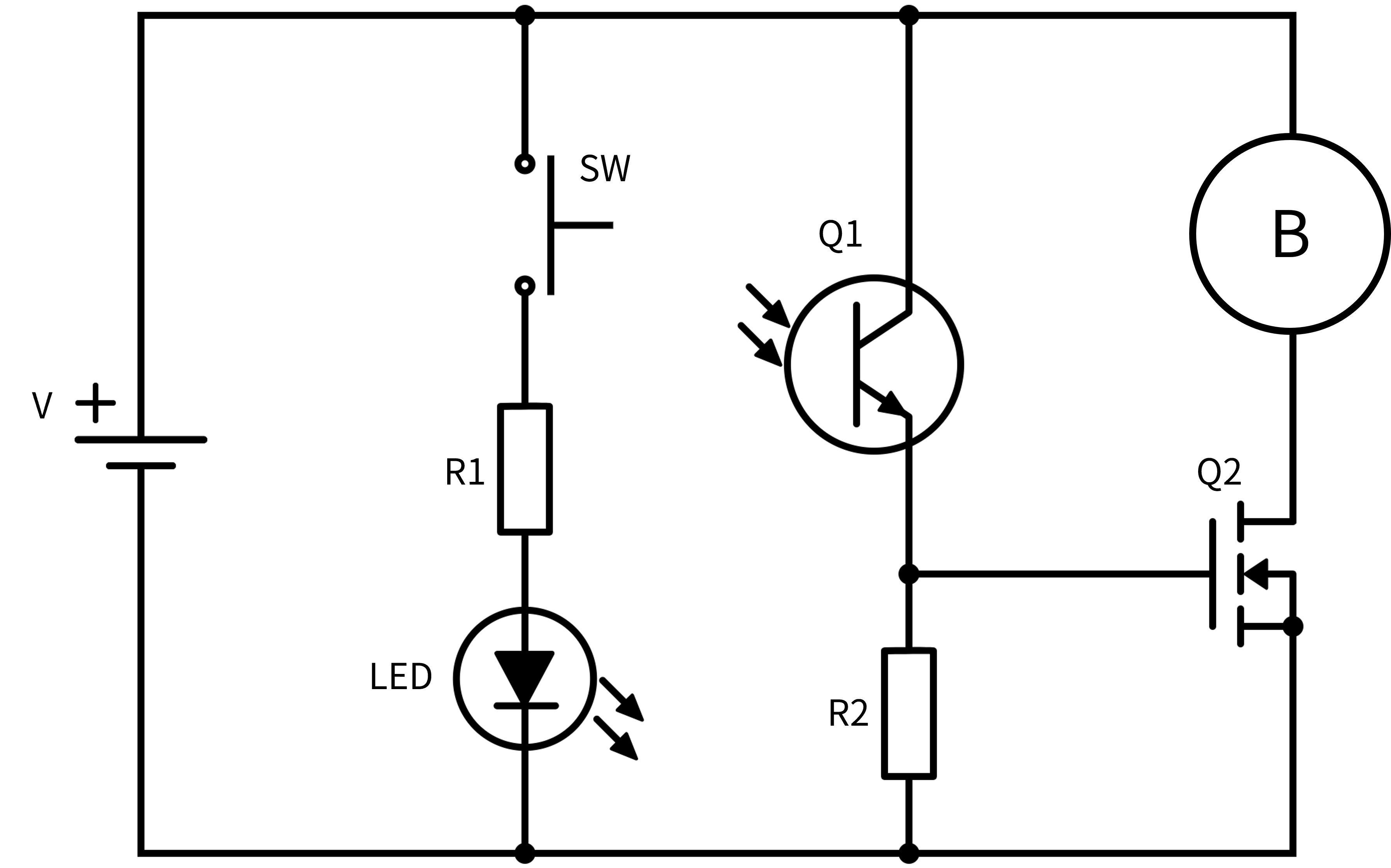
回路はLED信号送信部とLED信号受信部から構成する。 Vはコイン電池、SWはタクトスイッチ、Rは抵抗器、Q1はフォトトランジスタ、Bはブザー、Q2はNch MOSFETを表している。 ## 使用部品 順方向電圧$VF=2.1\,[\mathrm{V}]$の黄色LEDを使用する。このLEDの順方向電流の絶対最大定格は$IF=50\,[\mathrm{mA}]$である。…

Size
63 × 48.5 mm
Copper layers
2
Thickness
1.6 mm
Parts
8
Nets
8
Pads
20
Tracks, vias
23, 7
Pours
1
Routed
Yes
KiCad
KiCad 9.0 (file 20241229)
Created
1 Dec 2025
Updated
1 Dec 2025

Overview

LED Morsecode is an open-source printed circuit board by mrmtmtk03, from the mrmtmtk03/LED_Morsecode repository on GitHub. It is a 2-layer board of 63 × 48.5 mm with 8 parts on 8 nets, routed with 23 tracks and 7 vias.

It is built around the IRLU3410PBF and PKB24SPCH3601-B0.

Main components

2

README

readme.md

LED送受信回路

回路構成

まずは、回路の概要を回路図を作成しながら考える。 回路図はDigiKeyが提供しているScheme-itを用いて作成する。

回路はLED信号送信部とLED信号受信部から構成する。 Vはコイン電池、SWはタクトスイッチ、Rは抵抗器、Q1はフォトトランジスタ、Bはブザー、Q2はNch MOSFETを表している。 LED送受信回路の回路図

使用部品

順方向電圧$V_F=2.1,[\mathrm{V}]$の黄色LEDを使用する。このLEDの順方向電流の絶対最大定格は$I_F=50\,[\mathrm{mA}]$である。 今回は$I_F=12\,[\mathrm{mA}]$となるように抵抗R1を選定し、以下のようにR1を75 Ωと定める。

math
R_1=\frac{V-V_F}{I_F}=\frac{3-2.1}{0.012}=75\,[Ω]

MOSFETを除く回路を構成した状態で、Q1が受光した際の抵抗R2の端子間電圧が2.1V以上になるように選定する。 今回はR2を5.1 kΩとする。 具体的な使用部品は以下の表に示す。

部品型番秋月電子販売コード
コイン電池CR2032-
ボタン電池基板取付用ホルダーCH29-2032LF108965
タクトスイッチDTS-63-N-V-YLW103650
抵抗器75 Ω107802
抵抗器5.1 kΩ107832
黄色LEDOS5YKA3131A107206
フォトトランジスタL-31ROPT1C104213
電子ブザーPKB24SPCH3601-B0103958
NchパワーMOSFETIRLU3410PBF106025

回路作成

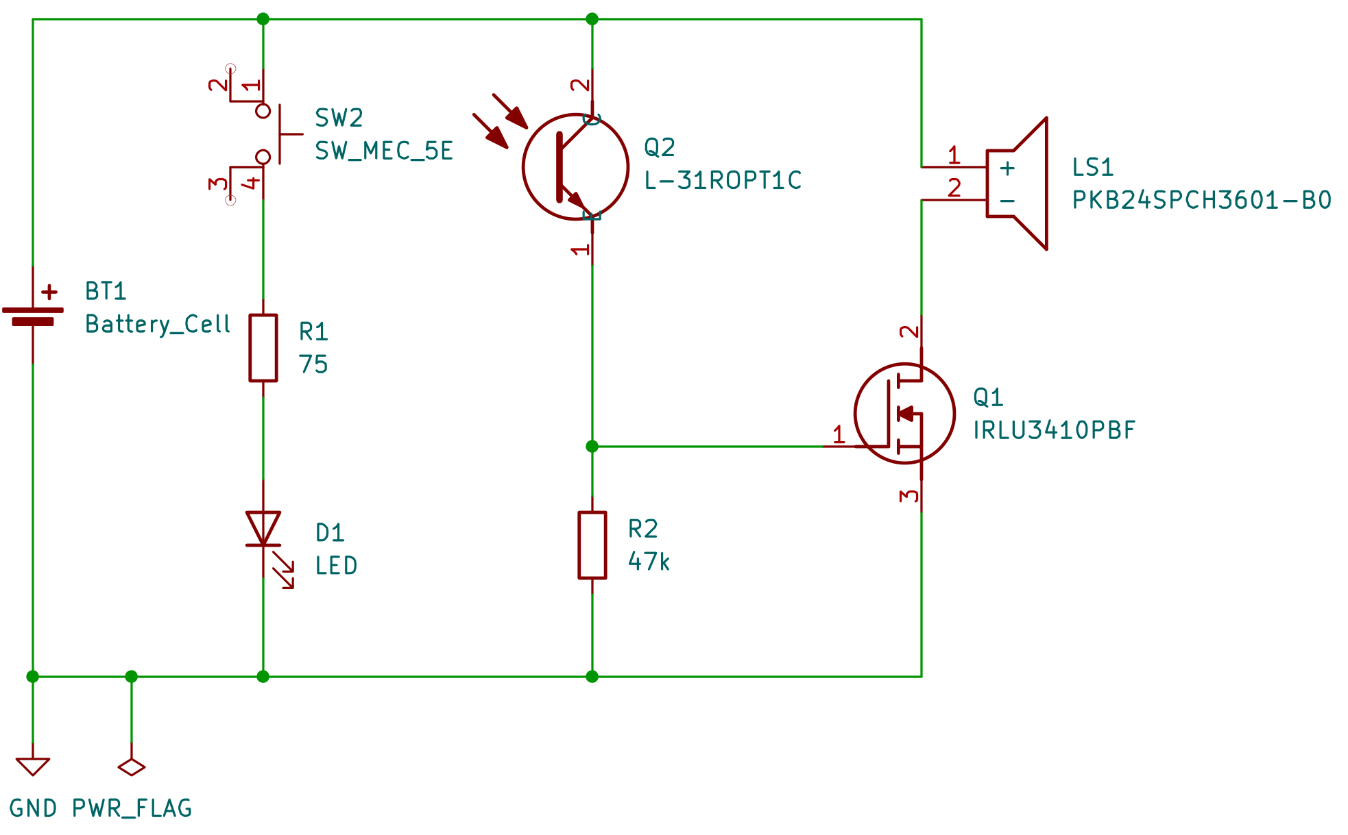
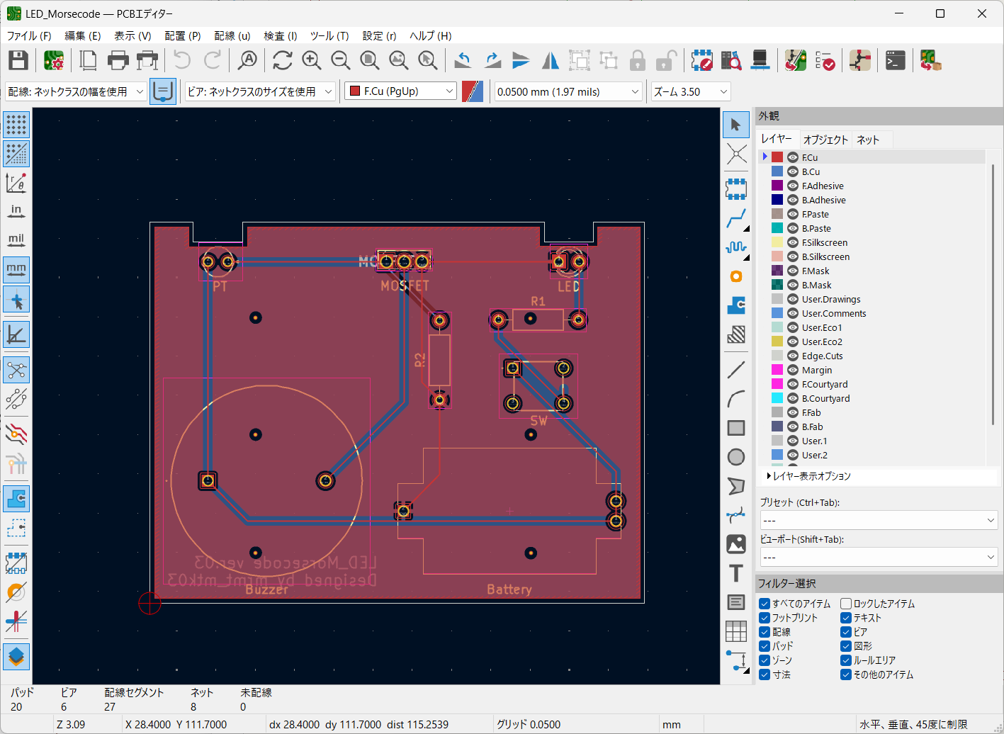
KiCadの回路図エディタで回路図を作成する。 回路図エディタで作成した回路図 次にPCBエディタで基板を設計する。 PCBエディタ このようなPCBを設計した。 作成したPCB

プリント基板の発注

設計した基板データは本リポジトリで公開している。 例えば、JLCPCBで発注する場合はZIPファイルLED_Morsecode_03_kicad\production\LED_Morsecode.zipをgerber fileとしてアップロードすることで基板を発注できる。

ただし、基板の発注内容に誤りがあった場合、その結果生じた発注者の不利益について、当方は責任を負いかねますので、ご了承ください。

Parts

8
QtyValueFootprintReferences
147kResistor_THT:R_Axial_DIN0207_L6.3mm_D2.5mm_P10.16mm_HorizontalR2
175Resistor_THT:R_Axial_DIN0207_L6.3mm_D2.5mm_P10.16mm_HorizontalR1
1Battery_CellBattery:CH29-2032LFBattery
1IRLU3410PBFIRLU3410PBF:TO229P239X654X978-3PMOSFET
1L-31ROPT1CL-31ROPT1C:L31ROPT1CPT
1LEDLED_THT:LED_D3.0mmLED
1PKB24SPCH3601-B0PKB24SPCH3601-B0:PKB24SPCH3601B0Buzzer
1SW_MEC_5EDTS-63N-V:DTS63NVSW

Questions

How big is the LED Morsecode PCB?

It measures 63 × 48.5 mm and has 2 copper layers, 1.6 mm thick.

What parts does the LED Morsecode use?

8 parts, built around the IRLU3410PBF and PKB24SPCH3601-B0. The full list of its parts is on this page, with links to each part's symbol and footprint where PCBKit's library has them.

Where can I download the LED Morsecode KiCad files?

From the mrmtmtk03/LED_Morsecode repository on GitHub, at the commit this page was made from: the board is LED_Morsecode_02_kicad/LED_Morsecode.kicad_pcb and its schematic LED_Morsecode_02_kicad/LED_Morsecode.kicad_sch. PCBKit opens the board in the browser, with nothing to install.

Can I use the LED Morsecode design in my own project?

Its repository states no licence, so its author keeps all rights: ask mrmtmtk03 before reusing the design.

More from mrmtmtk03/LED_Morsecode

1
  • 2 layers70.5 × 50 mmLED Morsecode, the printed circuit board in 3D

    LED Morsecode

    mrmtmtk03/LED_Morsecode

    回路はLED信号送信部とLED信号受信部から構成する。 Vはコイン電池、SWはタクトスイッチ、Rは抵抗器、Q1はフォトトランジスタ、Bはブザー、Q2はNch MOSFETを表している。 ## 使用部品 順方向電圧$VF=2.1\,[\mathrm{V}]$の黄色LEDを使用する。このLEDの順方向電流の絶対最大定格は$IF=50\,[\mathrm{mA}]$である。…

    8 parts

Similar boards

  • 2 layers72 × 80 mmSensing, the printed circuit board in 3D

    Sensing

    Olin-Rocketry/sensing

    Sensing hardware and software

    34 parts
  • 2 layers98.1 × 98.1 mmGroED, the printed circuit board in 3D

    GroED

    BB-KING777/Agri_iot_pcbs

    260 parts
  • 2 layers125 × 52 mmSyokkenki2-2, the printed circuit board in 3D

    Syokkenki2-2

    sakufff/future-ticket-machine

    M5Stack Future Ticket Machine production monorepo

    116 parts
  • 2 layers20.5 × 24.8 mmPi interface, the printed circuit board in 3D

    Pi interface

    opulo-inc/lumenpnp

    The LumenPnP is an open source pick and place machine.

    8 parts3.7k
  • 2 layers59.9 × 25.7 mmBuffer, the printed circuit board in 3D

    Buffer

    hoglet67/RGBtoHDMI

    Bare-metal Raspberry Pi project that provides pixel-perfect sampling of Retro Computer RGB/YUV video and conversion to HDMI

    8 parts1kGPL-3.0
  • 2 layers52 × 12.6 mmUSB, the printed circuit board in 3D

    USB

    shanteacontrols/OpenDeck

    A platform for building interactive control and sensing devices using MIDI and OSC built with Zephyr RTOS.

    8 parts960Apache-2.0