4 layers50 × 35 mm
PixAppleV1.1
mrkingseasheep/PixApple
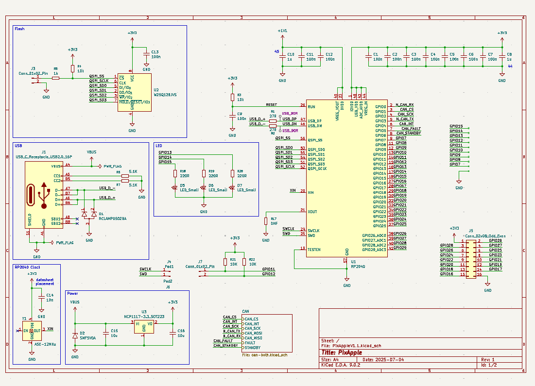
PixApple is designed as a RP2040 breakout board. It features 8 general use GPIOs, 1 SPI interface, 1 I2C interface, 4 ADC channels, 4 PWM channels and a CAN bus.
78 parts1GPL-3.0

 mrkingseasheep/PixApple1
PixApple is designed as a RP2040 breakout board. It features 8 general use GPIOs, 1 SPI interface, 1 I2C interface, 4 ADC channels, 4 PWM channels and a CAN bus.
PixAppleV1.0 is an open-source printed circuit board by mrkingseasheep, from the mrkingseasheep/PixApple repository on GitHub, published under the GPL-3.0 licence. It is a 2-layer board of 80 × 65 mm with 85 parts on 78 nets, routed with 769 tracks and 104 vias.
It is built around the RP2040, SN65HVD230DR and W25Q128JVSIQ, with the 1N5819WS, 1N4148W and ABM8-16.000MHZ-B2-T among its other parts. Its parts include 22 capacitors, 20 resistors, 15 connectors, 7 diodes and 5 ICs. It belongs with the interfaces and adapters boards and the RP2040 boards of this library.


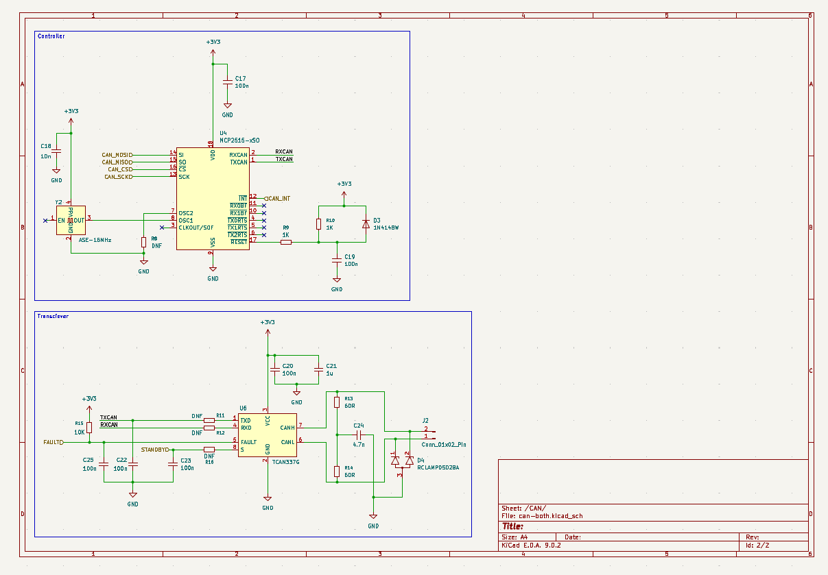
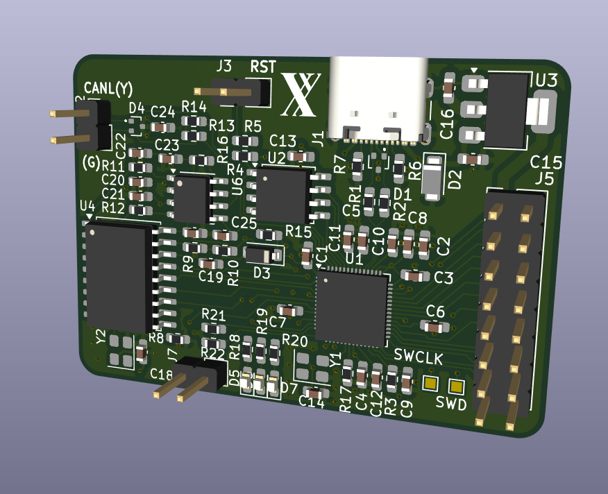
PixApple is designed as a RP2040 breakout board. It features 8 general use GPIOs, 1 SPI interface, 1 I2C interface, 4 ADC channels, 4 PWM channels and a CAN bus. I designed it because I wanted a board that I could use for general purpose robotics projects. Being from FRC, a CAN bus was a must so I added the CAN bus onto the RP2040 with split terminations. The Roborio is like 2000CAD so it's so far out of reach its funny. Of course, I don't need the real time OS or the robust nature of the thing, I just want to drive a lil car or something. So I created this! Building this project really gave me a greater understanding of what went on undernearth the Roborio (I never did open it) and everything actually kinda makes sense now. I chose the RP2040 because it is cheap, decently powerful for the basic robotics I plan on doing with it and is also what I'm used to. Additionally, I chose the 0603 SMT format because I wanted to be able to fix any problems I have later on with this board. This being V1.0, many of the values are not tested and I wanted the ability to fix them if anything happened. Finally, there are test points scattered around the board for easy debugging.
Total time spent: 51 hours (I'm still so slow at KiCAD) (the redo didn't help)
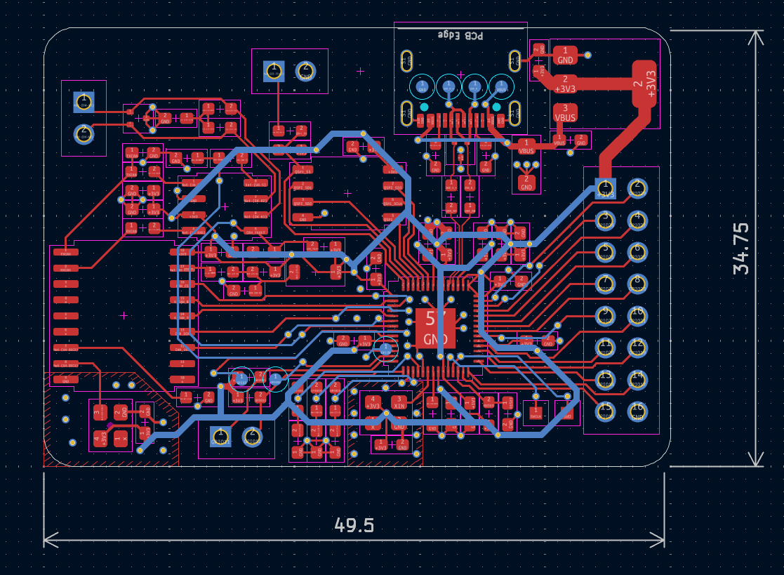
This is my first semi-intermediate project and I wanted to learn more about ICs in general. I've incorporated: wide power traces, equal length wires and a ground pour on top and bottom in this project.
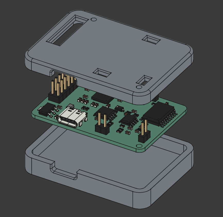
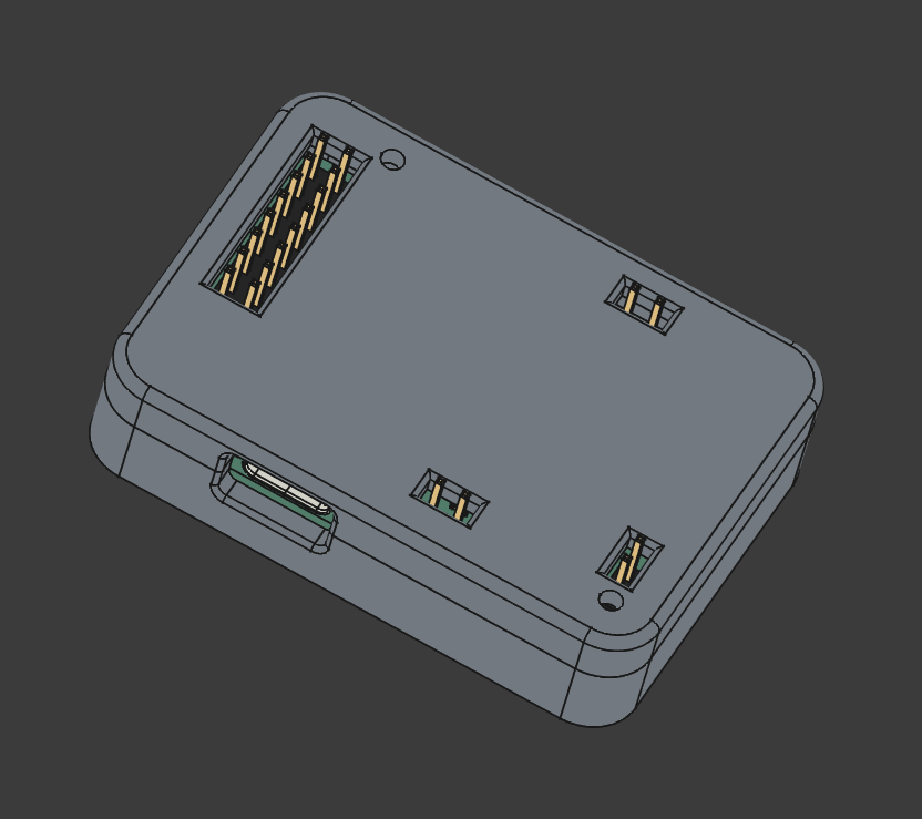
Total: 80 CAD
| Qty | Value | Footprint | References |
|---|---|---|---|
| 11 | 100n | Capacitor_SMD:C_0603_1608Metric_Pad1.08x0.95mm_HandSolder | C3, C4, C5, C6, C7, C12, C14, C17, C18, C22, C24 |
| 6 | 1k | Resistor_SMD:R_0603_1608Metric_Pad0.98x0.95mm_HandSolder | R2, R3, R7, R9, R17, R18 |
| 6 | Conn_01x01_Pin | TestPoint:TestPoint_Pad_1.0x1.0mm | J3, J4, J7, J28, J29, J30 |
| 4 | 10k | Resistor_SMD:R_0603_1608Metric_Pad0.98x0.95mm_HandSolder | R1, R6, R8, R10 |
| 4 | 1u | Capacitor_SMD:C_0603_1608Metric_Pad1.08x0.95mm_HandSolder | C10, C11, C23, C25 |
| 3 | Conn_01x02_Pin | Connector_PinHeader_2.54mm:PinHeader_1x02_P2.54mm_Vertical | J2, J6, J12 |
| 3 | LOGO | LOGO | G***, G***, G*** |
| 2 | 10u | Capacitor_SMD:C_0603_1608Metric_Pad1.08x0.95mm_HandSolder | C1, C2 |
| 2 | 15p | Capacitor_SMD:C_0603_1608Metric_Pad1.08x0.95mm_HandSolder | C15, C16 |
| 2 | 1N5819WS | Diode_SMD:D_SOD-323 | D4, D5 |
| 2 | 220R | Resistor_SMD:R_0603_1608Metric_Pad0.98x0.95mm_HandSolder | R13, R14 |
| 2 | 27R | Resistor_SMD:R_0603_1608Metric_Pad0.98x0.95mm_HandSolder | R4, R5 |
| 2 | 30p | Capacitor_SMD:C_0603_1608Metric_Pad1.08x0.95mm_HandSolder | C19, C20 |
| 2 | 4.7K | Resistor_SMD:R_0603_1608Metric_Pad0.98x0.95mm_HandSolder | R19, R20 |
| 2 | 5.1K | Resistor_SMD:R_0603_1608Metric_Pad0.98x0.95mm_HandSolder | R15, R16 |
| 2 | 60R | Resistor_SMD:R_0603_1608Metric_Pad0.98x0.95mm_HandSolder | R11, R12 |
| 2 | Conn_01x11 | Connector_PinHeader_2.54mm:PinHeader_1x11_P2.54mm_Vertical | J10, J11 |
| 2 | LED_Small | LED_SMD:LED_0603_1608Metric_Pad1.05x0.95mm_HandSolder | D2, D3 |
| 2 | SW_Push | Button_Switch_THT:SW_PUSH_6mm | SW1, SW2 |
| 2 | TestPoint_Pad_2.0x2.0mm | TestPoint:TestPoint_Pad_2.0x2.0mm | +3V3, GND |
| 1 | 1N4148W | Diode_SMD:D_SOD-123 | D1 |
| 1 | 4.7n | Capacitor_SMD:C_0603_1608Metric_Pad1.08x0.95mm_HandSolder | C21 |
| 1 | ABM8-16.000MHZ-B2-T | ABM8-16.000MHZ-B2-T:XTAL_ABM8-16.000MHZ-B2-T | Y2 |
| 1 | ABM8-272-T3 | ABM8-272-T3:XTAL_ABM8-272-T3 | Y1 |
| 1 | Conn_01x04_Pin | Connector_PinHeader_2.54mm:PinHeader_1x04_P2.54mm_Vertical | J9 |
| 1 | Conn_01x05_Pin | Connector_PinHeader_2.54mm:PinHeader_1x05_P2.54mm_Vertical | J5 |
| 1 | Conn_02x03_Odd_Even | Connector_PinHeader_2.54mm:PinHeader_2x03_P2.54mm_Vertical | J8 |
| 1 | MCP2515-xSO | Package_SO:SOIC-18W_7.5x11.6mm_P1.27mm | U5 |
| 1 | NCP1117-3.3_TO252 | Package_TO_SOT_SMD:TO-252-2 | U2 |
| 1 | PESD5V0S1UL | Diode_SMD:D_SOD-882 | D6 |
| 1 | RCLAMP0502B | Package_TO_SOT_SMD:SOT-416 | D8 |
| 1 | RP2040 | Package_DFN_QFN:QFN-56-1EP_7x7mm_P0.4mm_EP3.2x3.2mm | U1 |
| 1 | SN65HVD230DR | SN65HVD230DR:SOIC127P599X175-8N | U4 |
| 1 | USB_C_Receptacle_USB2.0_16P | Connector_USB:USB_C_Receptacle_GCT_USB4105-xx-A_16P_TopMnt_Horizontal | J1 |
| 1 | W25Q128JVS | Package_SO:SOIC-8_5.3x5.3mm_P1.27mm | U3 |
The 78 most common of 85 parts.
mrkingseasheep/PixApple
PixApple is designed as a RP2040 breakout board. It features 8 general use GPIOs, 1 SPI interface, 1 I2C interface, 4 ADC channels, 4 PWM channels and a CAN bus.

SshgurkiratSingh/CCMS_PORTAL
A full-stack smart streetlight fleet management system with real-time monitoring, remote control, and analytics.


esb8/AvionicsPower
PCB of a Power Management and supply board for an Avionics stack.


dchwebb/Oscar
Eurorack 3 Channel Oscilloscope based on ARM STM32F446 MCU


It measures 80 × 65 mm and has 2 copper layers, 1.6 mm thick.
85 parts, built around the RP2040, SN65HVD230DR, W25Q128JVSIQ and 1N5819WS. The full list of its parts is on this page, with links to each part's symbol and footprint where PCBKit's library has them.
From the mrkingseasheep/PixApple repository on GitHub, at the commit this page was made from: the board is PCB/PixAppleV1.0.kicad_pcb and its schematic PCB/PixAppleV1.0.kicad_sch. PCBKit opens the board in the browser, with nothing to install.
Its repository publishes it under the GPL-3.0 licence: you may reuse it on that licence's terms (keep the author's notice, and for a copyleft licence share your changes alike).