2 layers89.6 × 79 mm
TDR 5351 core
MR-DOS/TDR_diploma_thesis
Time domain reflectometer. Includes Hardware, firmware and GUI in Octave. Also a diploma thesis.
199 parts33GPL-3.0

 MR-DOS/TDR-avalanche11
Avalanche pulser for use as TDR core
TDR avalanche is an open-source printed circuit board by MR-DOS, from the MR-DOS/TDR-avalanche repository on GitHub, published under the GPL-3.0 licence. It is a 2-layer board of 73.9 × 46 mm with 80 parts on 50 nets, routed with 208 tracks and 65 vias.
It is built around the 100N50TW, MC34063AD and 74LVC04AD, with the XC6206-3.3V, 1N4148WS and BC817 among its other parts. Its parts include 36 resistors, 17 capacitors, 6 diodes, 5 connectors and 3 ICs. It belongs with the radio and wireless boards of this library.


Simple flat-top avalanche pulser with integrated power supply for the avalanche transistor circuit and trigger circuitry.
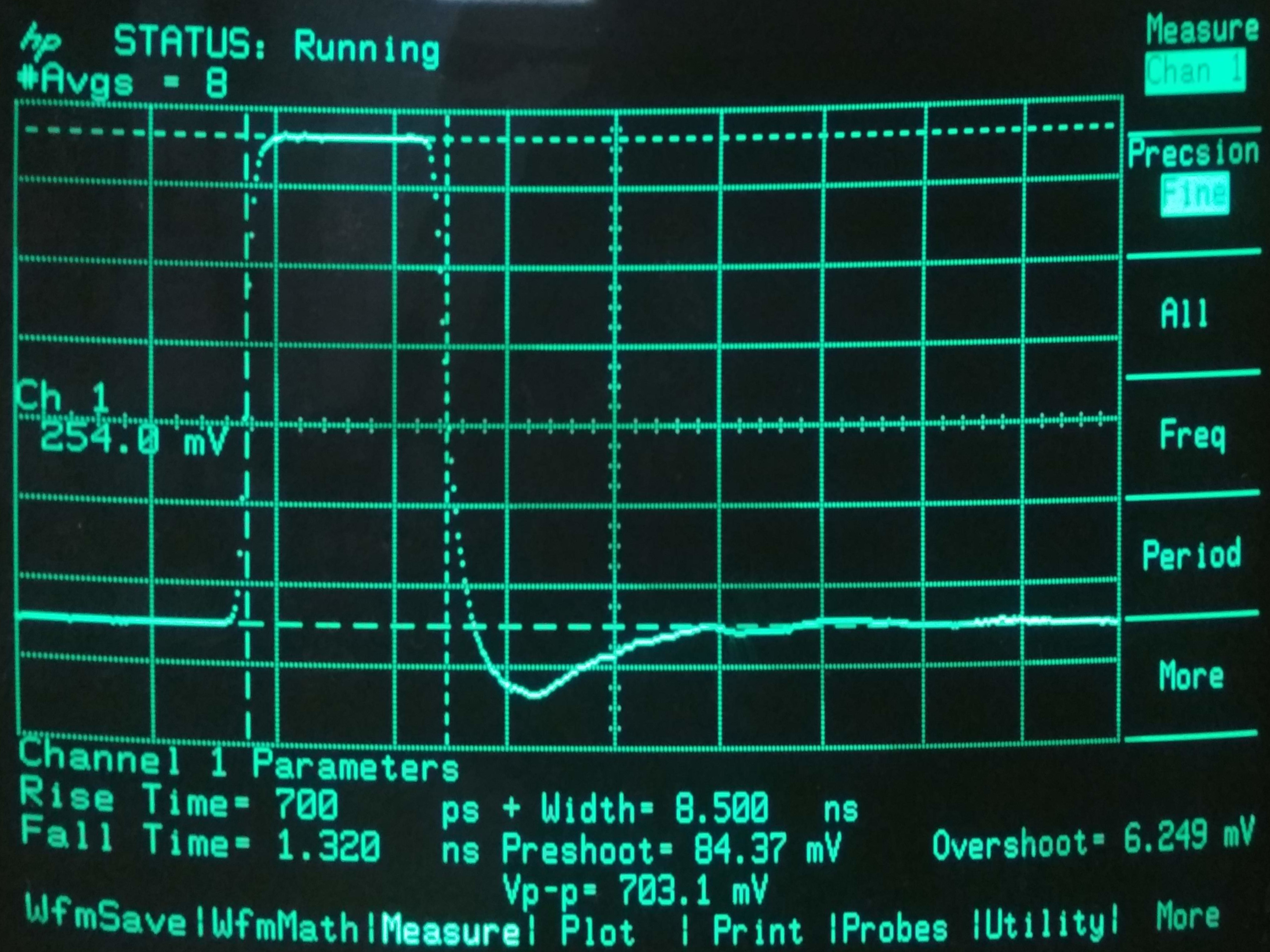
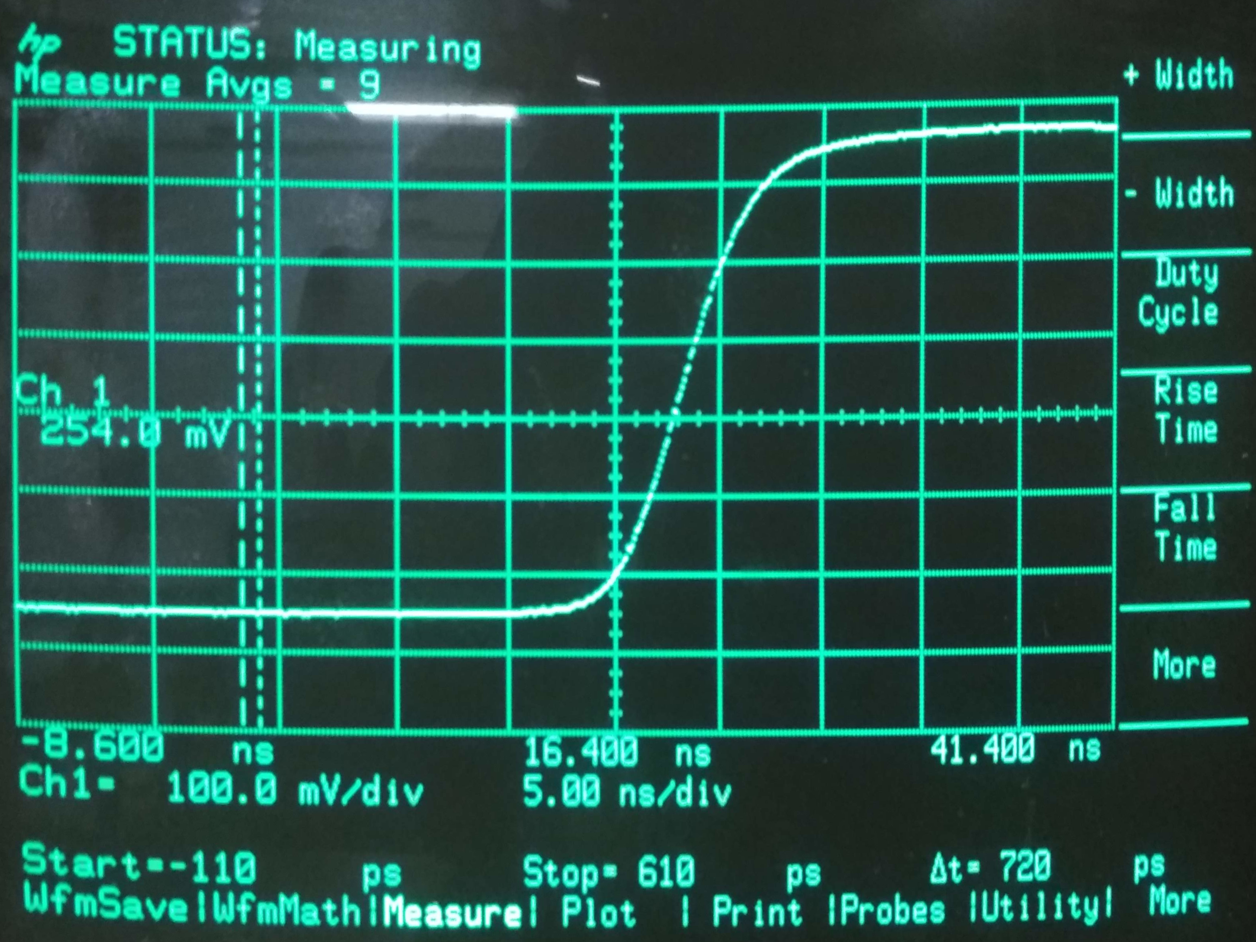
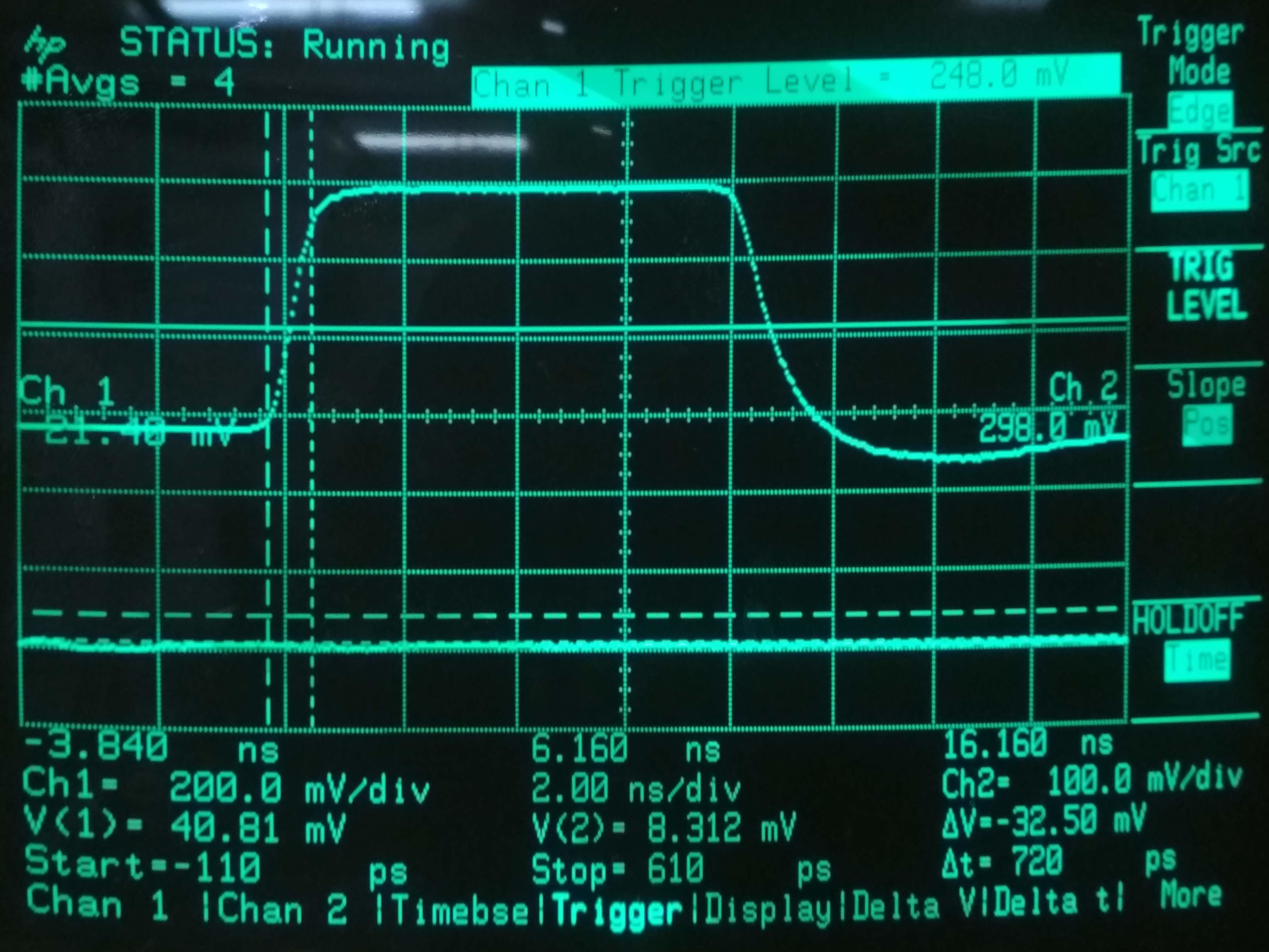
This pulser was made in hope to use it to measure reflections on cables. However, using the transistor 2SC5773, it was not possible to obtain faster risetime than about 700 ps. This allows to measure reflections, but the resolution is quite limited due to the shape of the pulse (slow risetime and a backlash after the falling edge). Maybe using some other transistor and changing the compensation circuitry, it could be made better. Since there are many PECL buffers with rise and fall times faster than 200 ps (and reproducible), the next one will use some IC to generate the pulses. Also, generating short rectangular pulse is not very good if you want to postprocess the data, because you would need to run a decorrelation to find out what is happening on the cable. Using a long rectangular pulse (with infinitesimally fast edges) where all of the reflected energy comes back before the falling edge allows you to derive the signal which in turn gives you impulse response.
The pulser contains a 40V power supply followed by denoising network and 6V - 35V regulated linear supply to set the avalanche voltage. The whole board is powered from 5V using Mini USB-B, consuming less than 100 mA.
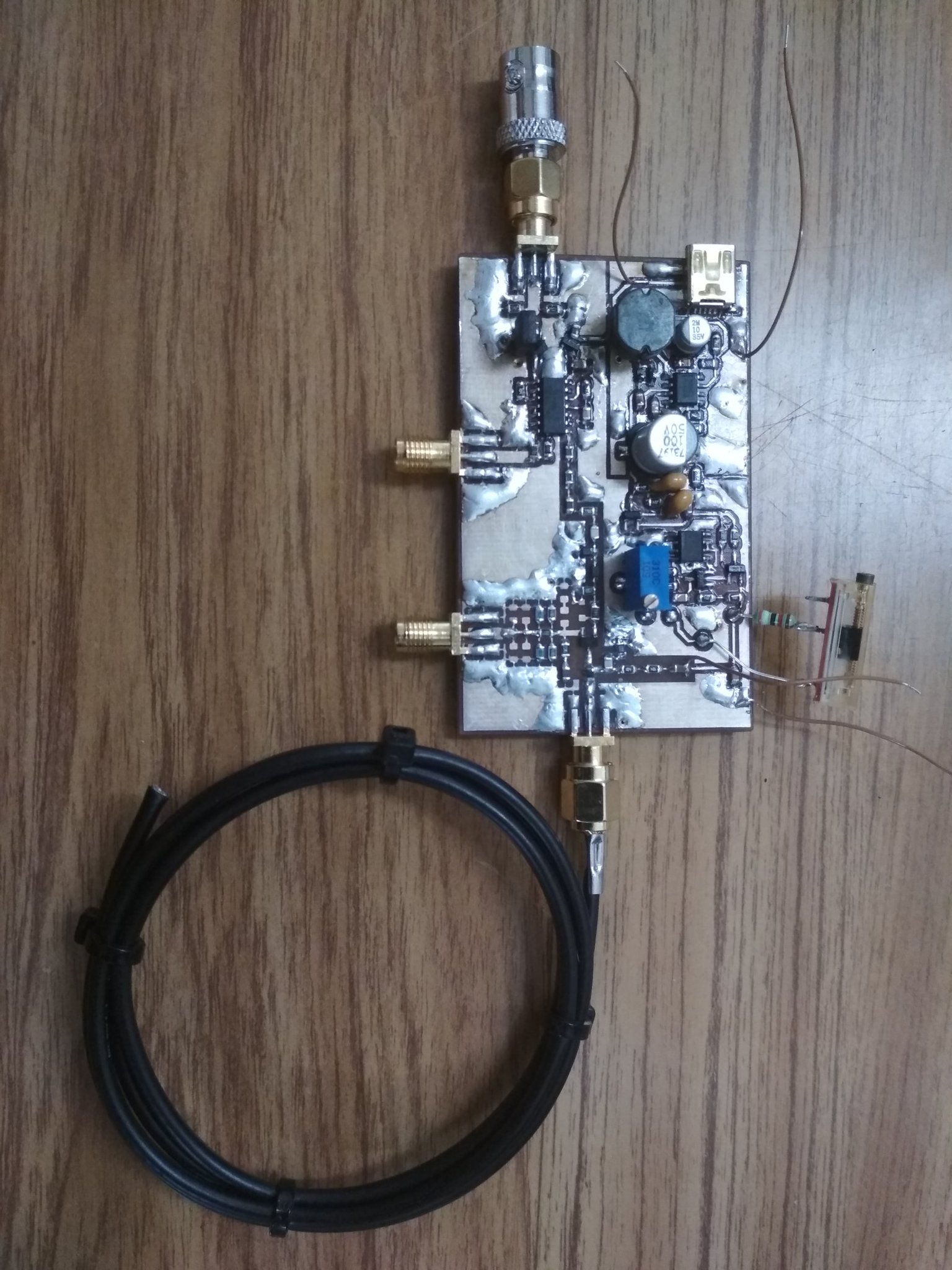
The avalanche pulser uses 2SC5773 transistor (6V NPN, fT=10.8 GHz @ 50 mA). The compensation circuitry makes the output pulse a nice clean rectangular pulse with a flat top with no visible ringing (invisible with 1 GHz oscilloscope, to be precise), however there is a not very nice backlash after the falling edge (see pictures). The transistor does not self-avalanche when set properly, it has to be triggered by external source. I used 8-10 kHz triggering during the development and use. There are 2 SMA connectors, one for coaxial cable where energy for the pulse is stored (length of the cable determines length of the pulse) and one where the pulses are output.
The trigger circuitry triggers avalanche on rising edge of the input trigger signal. There is RC circuit which sets the time between the trigger and avalanche. However, it seems to have quite large jitter. There is also trigger output which you can connect to scilloscope (the avalanche happens on falling edge of the TRIG OUT). The trigger circuitry can be inhibited using the jumper JP1 when tuning the avalanche voltage.
There are 2 attenuator sections giving 11.3 and 7.9 dB attenuation. The first one is mandatory as it is an impedance matching circuit. The second one is just a normal attenuator and can be omitted.
Connect square wave generator to the SYNC_IN port. Connect an oscilloscope to the SYNC_OUT port and to the PULSE_OUT port. Connect the coaxial cable to be measured to the STORAGE_COAX port. The cable MUST NOT have any shorts in it or any low impedance termination, because it is connected to the collector network and it would load the 200k resistor and the transistor would not avalanche. This severely limits the useability, so this mode is not recommended.
Connect square wave generator to the SYNC_IN port. Connect storage coaxial cable to the STORAGE_COAX port. You should use some 50 Ohm cable with low losses, ideally some rigid or semirigid cable. I used RG-174 because I had a lot of it on hand and the circuit is tweaked for use with the RG-174 (I used about one meter of the cable which gave me about 8 ns long pulse). Connect the PULSE_OUT port to anything you want (50 Ohm terminated).
Oscillogram of the whole pulse:
 Oscillogram of the rising edge:
 Oscillogram of the zoomed in pulse:
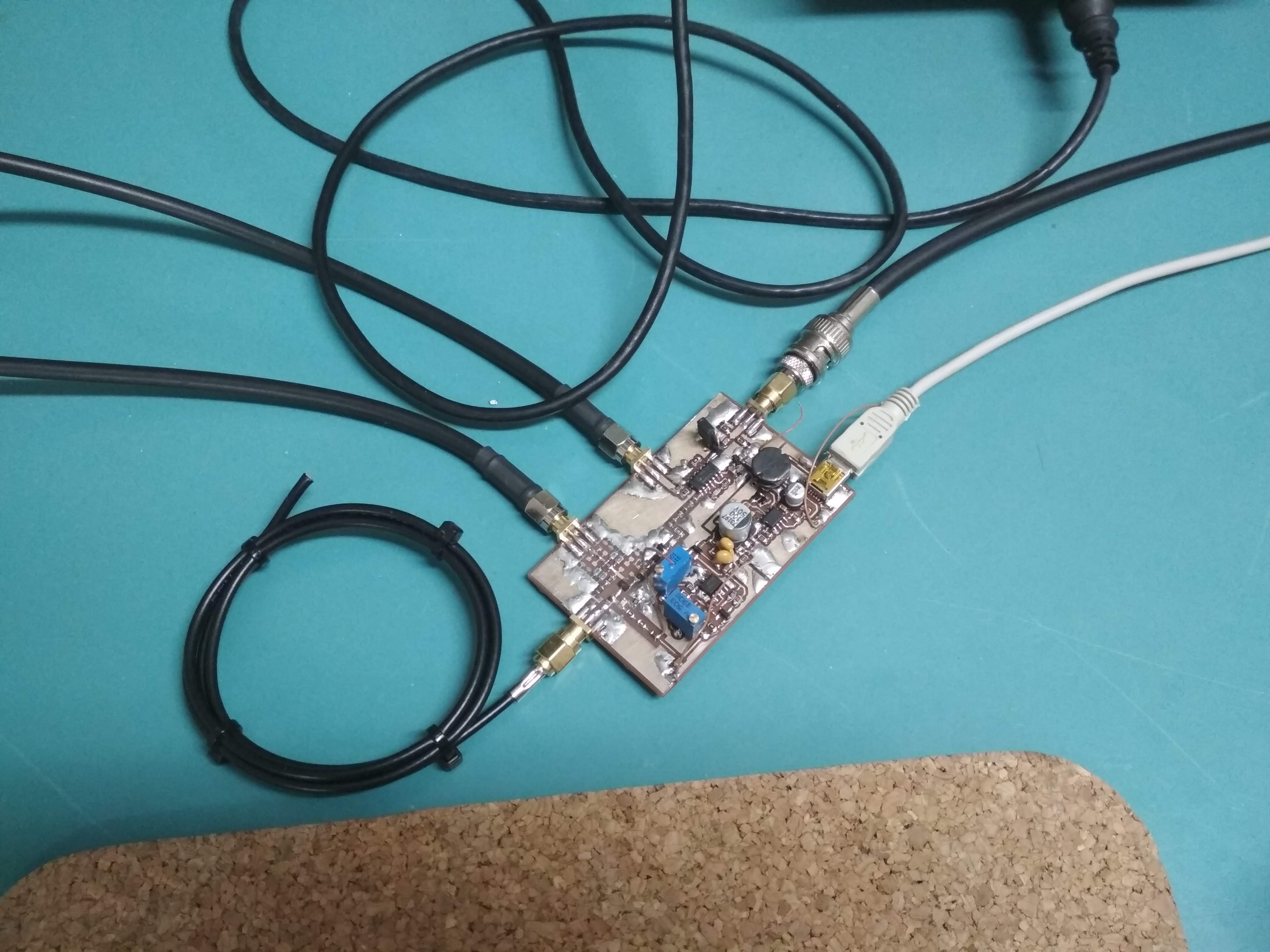
 Picture of the made and assembled PCB:
 Picture of the PCB connected to oscilloscope and generator:
AN-94: Slew Rate Verification for Wideband Amplifiers
AN-72: A Seven-Nanosecond Comparator for Single Supply Operation
Tweet with photo of the etched PCB
| Qty | Value | Footprint | References |
|---|---|---|---|
| 5 | 100k | Resistor_SMD:R_0805_2012Metric_Pad1.15x1.40mm_HandSolder | R4, R6, R12, R14, R19 |
| 5 | 1N4148WS | Diode_SMD:D_SOD-323_HandSoldering | D1, D2, D4, D5, D101 |
| 4 | 220R | Inductor_SMD:L_0805_2012Metric_Pad1.15x1.40mm_HandSolder | FB1, FB2, FB3, FB4 |
| 3 | 100 | Resistor_SMD:R_0805_2012Metric_Pad1.15x1.40mm_HandSolder | R18, R27, R103 |
| 3 | 1k | Resistor_SMD:R_0805_2012Metric_Pad1.15x1.40mm_HandSolder | R3, R10, R22 |
| 3 | 220 | Resistor_SMD:R_0805_2012Metric_Pad1.15x1.40mm_HandSolder | R16, R30, R31 |
| 3 | 51 | Resistor_SMD:R_0805_2012Metric_Pad1.15x1.40mm_HandSolder | R20, R21, R34 |
| 2 | 100n | Capacitor_SMD:C_0805_2012Metric_Pad1.15x1.40mm_HandSolder | C3, C11 |
| 2 | 100n/50 | Capacitor_SMD:C_0805_2012Metric_Pad1.15x1.40mm_HandSolder | C7, C10 |
| 2 | 10k | Resistor_SMD:R_0805_2012Metric_Pad1.15x1.40mm_HandSolder | R5, R23 |
| 2 | 1u | Capacitor_SMD:C_0805_2012Metric_Pad1.15x1.40mm_HandSolder | C2, C101 |
| 2 | 240 | Resistor_SMD:R_0805_2012Metric_Pad1.15x1.40mm_HandSolder | R32, R33 |
| 2 | 2R2 | Resistor_SMD:R_0805_2012Metric_Pad1.15x1.40mm_HandSolder | R1, R101 |
| 2 | 47 | Resistor_SMD:R_0805_2012Metric_Pad1.15x1.40mm_HandSolder | R24, R25 |
| 2 | 470 | Resistor_SMD:R_0805_2012Metric_Pad1.15x1.40mm_HandSolder | R28, R29 |
| 2 | 680n/50 | Capacitor_SMD:C_0805_2012Metric_Pad1.15x1.40mm_HandSolder | C8, C9 |
| 1 | 100p | Capacitor_SMD:C_0805_2012Metric_Pad1.15x1.40mm_HandSolder | C15 |
| 1 | 100u/50 | Capacitor_SMD:CP_Elec_8x6.9 | C6 |
| 1 | 10n | Inductor_SMD:L_0805_2012Metric_Pad1.15x1.40mm_HandSolder | L2 |
| 1 | 10n | Capacitor_SMD:C_0805_2012Metric_Pad1.15x1.40mm_HandSolder | C1 |
| 1 | 10u | Capacitor_SMD:CP_Elec_4x5.3 | C4 |
| 1 | 110R | Resistor_SMD:R_0805_2012Metric_Pad1.15x1.40mm_HandSolder | R15 |
| 1 | 15 | Resistor_SMD:R_0805_2012Metric_Pad1.15x1.40mm_HandSolder | R26 |
| 1 | 180 | Resistor_SMD:R_0805_2012Metric_Pad1.15x1.40mm_HandSolder | R2 |
| 1 | 1n | Capacitor_SMD:C_0805_2012Metric_Pad1.15x1.40mm_HandSolder | C13 |
| 1 | 22 | Resistor_SMD:R_0805_2012Metric_Pad1.15x1.40mm_HandSolder | R104 |
| 1 | 220u | Inductor_SMD:L_7.3x7.3_H4.5 | L1 |
| 1 | 2N7002 | Package_TO_SOT_SMD:SOT-23_Handsoldering | Q1 |
| 1 | 2SC5773 | Package_TO_SOT_SMD:SC-59_Handsoldering | Q4 |
| 1 | 30k | Resistor_SMD:R_0805_2012Metric_Pad1.15x1.40mm_HandSolder | R8 |
| 1 | 3p3 | Capacitor_SMD:C_0805_2012Metric_Pad1.15x1.40mm_HandSolder | C16 |
| 1 | 3p9 | Capacitor_SMD:C_0805_2012Metric_Pad1.15x1.40mm_HandSolder | C12 |
| 1 | 4R7 | Resistor_SMD:R_0805_2012Metric_Pad1.15x1.40mm_HandSolder | R102 |
| 1 | 4k3 | Resistor_SMD:R_0805_2012Metric_Pad1.15x1.40mm_HandSolder | R13 |
| 1 | 500 | Potentiometer_THT:Potentiometer_Bourns_3296Y_Vertical | RV2 |
| 1 | 50k | Potentiometer_THT:Potentiometer_Bourns_3296Y_Vertical | RV1 |
| 1 | 510 | Resistor_SMD:R_0805_2012Metric_Pad1.15x1.40mm_HandSolder | R17 |
| 1 | 680p | Capacitor_SMD:C_0805_2012Metric_Pad1.15x1.40mm_HandSolder | C5 |
| 1 | 6k8 | Resistor_SMD:R_0805_2012Metric_Pad1.15x1.40mm_HandSolder | R9 |
| 1 | 6n8 | Inductor_SMD:L_0805_2012Metric_Pad1.15x1.40mm_HandSolder | L101 |
| 1 | 6p8 | Capacitor_SMD:C_0805_2012Metric_Pad1.15x1.40mm_HandSolder | C14 |
| 1 | 74LVC04 | Package_SO:SOIC-14_3.9x8.7mm_P1.27mm | U2 |
| 1 | BC817 | Package_TO_SOT_SMD:SOT-23_Handsoldering | Q2 |
| 1 | DISABLE_TRIGGER | Connector_PinHeader_2.54mm:PinHeader_1x02_P2.54mm_Vertical_SMD_Pin1Right | JP1 |
| 1 | MC34063AD | Package_SO:SOIC-8_3.9x4.9mm_P1.27mm | U1 |
| 1 | PULSE_OUT | petr_kicad:Molex_SMA_Jack_Edge_Mount_Chinese | J4 |
| 1 | STORAGE_COAX | petr_kicad:Molex_SMA_Jack_Edge_Mount_Chinese | J2 |
| 1 | SYNC_IN | petr_kicad:Molex_SMA_Jack_Edge_Mount_Chinese | J3 |
| 1 | SYNC_OUT | petr_kicad:Molex_SMA_Jack_Edge_Mount_Chinese | J5 |
| 1 | TL431D | Package_SO:SOIC-8_3.9x4.9mm_P1.27mm | D3 |
| 1 | USB_B_Mini | Connector_USB:USB_Mini-B_Lumberg_2486_01_Horizontal | J1 |
| 1 | XC6206-3.3 | Package_TO_SOT_SMD:SOT-23_Handsoldering | U101 |
It measures 73.9 × 46 mm and has 2 copper layers, 1.6 mm thick.
80 parts, built around the 100N50TW, MC34063AD, 74LVC04AD and XC6206-3.3V. The full list of its parts is on this page, with links to each part's symbol and footprint where PCBKit's library has them.
From the MR-DOS/TDR-avalanche repository on GitHub, at the commit this page was made from: the board is TDR_avalanche.kicad_pcb. PCBKit opens the board in the browser, with nothing to install.
Its repository publishes it under the GPL-3.0 licence: you may reuse it on that licence's terms (keep the author's notice, and for a copyleft licence share your changes alike).
MR-DOS/TDR_diploma_thesis
Time domain reflectometer. Includes Hardware, firmware and GUI in Octave. Also a diploma thesis.

dermatoid-collab/EVC_FW
Progetto hardware e firmware del sistema di controllo di un ascensore domestico a trazione (TTF) di LiftingItalia s.r.l. Quattro schede basate su STM32F446, collegate in CAN; il motore è comandato da un VFD.

basson/qym-solder
QymSolder - Soldering station three in one - hakko t12, hot air gun, d909/898D or analog.


c0pperdragon/LumaCode
Definition of the "LumaCode" signal standard with reference implementation

garrettsworkshop/TimeDisk
Apple II memory expansion card with 1 MB battery-backed RAM and NoSlotClock-compatible clock

