2 layers80.2 × 55.5 mm
 moosh/switchy2
Smart Wireless Integrated Train Control Hub sYstem
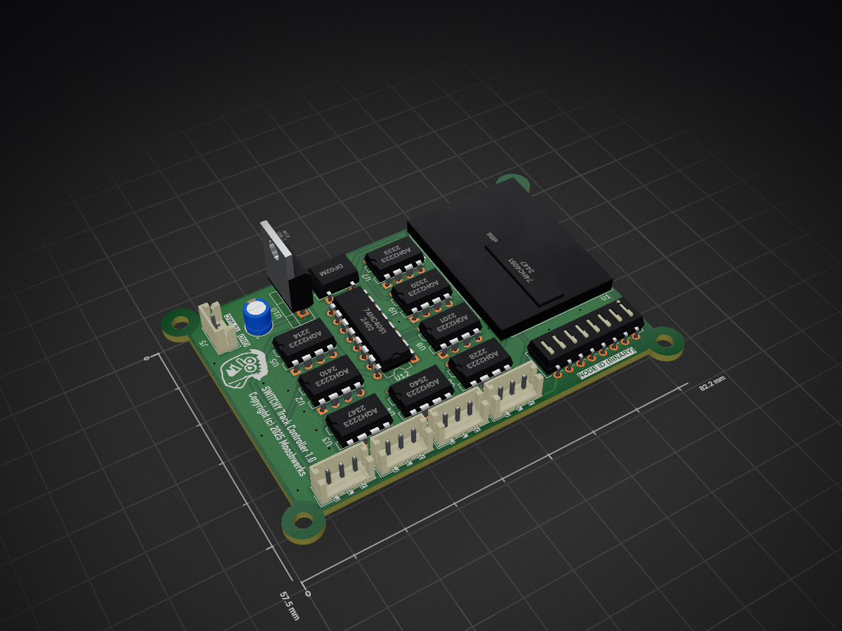
Switchy is an open-source printed circuit board by moosh, from the moosh/switchy repository on GitHub. It is a 2-layer board of 80.2 × 55.5 mm with 33 parts on 51 nets, routed with 295 tracks and 44 vias.
It is built around the WEMOS D1 MINI, AQH2223 and 74HC4051, with the L7805 and DF02M among its other parts. Its parts include 12 ICs, 8 resistors, 5 connectors, 1 capacitor and 1 diode. It belongs with the ESP8266 boards of this library.


Smart Wireless Integrated Train Control Hub sYstem
The goal of this project is to create a freely available digital on-ramp for older Märklin train setups. If you have a wildly-wired analog train system, you may gain some flexibility by using the hardware and software described below. The hardware is designed to be as "set it and forget it" as possible. The software required is minimal and accessible to non-programmers.
TL;DR
I must say up front, my friend Bert is the train enthusiast, and I just like building things. Please forgive me if I use the wrong train terminology! Together we discussed how to move toward some software control over his setup. Early on Bert found the excellent YouTube channel The3rdRail. The hardware that follows was inspired by the train setup glimpsed there.
Currently, the SWITCHY system has two different wi-fi enabled boards. Each board connects to a particular kind of track.
NOTE: No other hardware, other than a computer or tablet, is necessary. When powered up these boards find each other and self-assemble into a small local wi-fi network. From there it's up to you, using software tools described below, to control your actual train layout.
The first is the white-colored board that allows you to control up to four Märklin turnouts. Alternatively, up to eight other accessories that take 16VAC. Here is one of the four turnout's connected and a close-up of the board:


The second is the blue-colored board that waits for a train to brush across a contact, left or right, in a track section. It then broadcasts this "event" and allows you to take any desired action.


Full KiCad schematics and PCB layout documents for each board are available in this archive.


Each board is currently powered by an ESP8266 microcontroller, specifically a WeMOS-like MCU. I've found much joy in this little device, and it's built-in wi-fi support.
All communication is via an ad-hoc MQTT network set up over wi-fi. Each board (also referred to as a node) is given a unique nodeID via its onboard 8-gang DIP switch. (See the software section below for a discussion on 8-bit binary notation). The board with nodeID = 0 (and there must be one board with nodeID zero) performs multiple duties. Along with controlling turnout switches it creates a wi-fi access point (hotspot), named "SWITCHY Network", requiring no password, at IP address 192.168.4.1. It also operates an MQTT server. This server is how all nodes communicate with each other and the control software (discussed below).
The network that forms allows up to 256 boards of each type. This means that the SWITCHY network supports controlling up to 1024 Märklin turnouts, or up to 1024 contact switch track sections.
Any software system that supports communicating with an MQTT server can be used to control the SWITCHY network. Perhaps the easiest to use for non-programmers is Node-Red or n8n. Installation and basics of these platforms is outside the scope of this README so please refer to the links above for those details.
NOTE: The terms "board" and "node" are used interchangeably in the following discussion. Node primarily is used when talking about the board's software representation on the SWITCHY network.
The white-board (turnout switcher) listens for MQTT messages on the switchy/track_switching channel. From Node-RED, etc. you send MQTT messages on this channel to make the desired switch move. Messages are formed using JSON. Here's an example message you an send to a white board:
{ "nodeID": 3, "switchIndex": 1, "direction": "straight" }
nodeID: MQTT supports a publish/subscribe architecture used by the SWITCHY network. This means that every subscriber hears the same published message. The JSON message, above, includes a nodeID to indicate for which node the message is meant. All other nodes ignore the message.
switchIndex: The one-based index of the switch to be modified. Current versions of the white board support up to four Märklin turnouts. The switchIndex ranges in 1 to 4.
direction: Determines which way the track is to be switched. Should be one of "straight" or "round".
The blue-board (contact listener) will send a MQTT message on the switchy/contact_switching channel. Your Node-Red, etc. code will listen on this channel and react when messages arrive. For example, you might toggle one or more turnout switches based on your track layout. Like the white board's message format, the blue board also uses JSON. Here's an example message sent from a blue board:
{ "nodeID": 3, "switchIndex": 11, "direction": "left" }
nodeID: The ID of the node meant as the message's target. All other nodes ignore the message.
switchIndex: The one-based index of the switch toggled by a moving train, etc. Current versions of the blue board support up to four Märklin contact switch tracks. The switchIndex ranges in 1 to 4.
direction: One of "left" or "right". These directions are relative to the contact switch track section when the Märklin plug-ins are facing you.
With these two items, it's possible to control and react to a large number of track sections.
Each board on the SWITCHY network must have a unique nodeID. The DIP switches on each board allows you to set this ID. The eight DIP switches allow you to create an 8-bit binary number as an ID.
As mentioned above nodeID = 0 is a special node. There must be one and only one board with nodeID of zero. All other boards must have a non-zero, unique, nodeID. What this means in practice is one board has all DIP switches set to 0:

All other nodes have a unique nodeID, for example here's one set to 9:

Please check out this page for a discussion on counting in binary.
| Qty | Value | Footprint | References |
|---|---|---|---|
| 8 | AQH2223 | Package_DIP:DIP-8-N7_W7.62mm | U2, U3, U4, U5, U6, U7, U8, U9 |
| 8 | R | Resistor_THT:R_Axial_DIN0204_L3.6mm_D1.6mm_P5.08mm_Horizontal | R1, R2, R3, R4, R5, R6, R7, R8 |
| 2 | 74HC4051 | Package_DIP:DIP-16_W7.62mm | U11, U12 |
| 1 | 100uf | Capacitor_THT:CP_Radial_D5.0mm_P2.50mm | C1 |
| 1 | AC Power | Connector_JST:JST_EH_B2B-EH-A_1x02_P2.50mm_Vertical | J5 |
| 1 | DF02M | Diode_THT:Diode_Bridge_DIP-4_W7.62mm_P5.08mm | D1 |
| 1 | L7805 | Package_TO_SOT_THT:TO-220-3_Vertical | U10 |
| 1 | LOGO | custom footprints:the_bag_gray_10x10 | G*** |
| 1 | SW_DIP_x08 | Button_Switch_THT:SW_DIP_SPSTx08_Slide_6.7x21.88mm_W7.62mm_P2.54mm_LowProfile | SW2 |
| 1 | Track SW1 | Connector_JST:JST_EH_B3B-EH-A_1x03_P2.50mm_Vertical | J1 |
| 1 | Track SW2 | Connector_JST:JST_EH_B3B-EH-A_1x03_P2.50mm_Vertical | J2 |
| 1 | Track SW3 | Connector_JST:JST_EH_B3B-EH-A_1x03_P2.50mm_Vertical | J3 |
| 1 | Track SW4 | Connector_JST:JST_EH_B3B-EH-A_1x03_P2.50mm_Vertical | J4 |
| 1 | WeMos_D1_mini | Module:WEMOS_D1_mini_light | U1 |
The 29 most common of 33 parts.
It measures 80.2 × 55.5 mm and has 2 copper layers, 1.6 mm thick.
33 parts, built around the WEMOS D1 MINI, AQH2223, 74HC4051 and L7805. The full list of its parts is on this page, with links to each part's symbol and footprint where PCBKit's library has them.
From the moosh/switchy repository on GitHub, at the commit this page was made from: the board is kicad_controller/switchy.kicad_pcb and its schematic kicad_controller/switchy.kicad_sch. PCBKit opens the board in the browser, with nothing to install.
Its repository states no licence, so its author keeps all rights: ask moosh before reusing the design.


bquangDinh/diy-esp32-thermostat
Design custom thermostat with ESP32, using 24VAC, battery management for backup, USB, etc


liveboxandy/ZX-Max-128-Issue-3
KiCAD created files for the ZX Max 128 Issue 3 designed by DonSuperfo


