4 layers100 × 82.2 mm
4 Bit - Seven Seg Interface
Shaxzodm2611/4-bit-Adder-Interface-Board
A custom PCB designed to mimic the function of a CPU. Entirely made from discrete logic ICs.
128 parts

 mohd-hani/555-Timer-Project
This project is a KiCad-designed circuit board centered around the 555 timer IC, which serves as a versatile timer and oscillator.
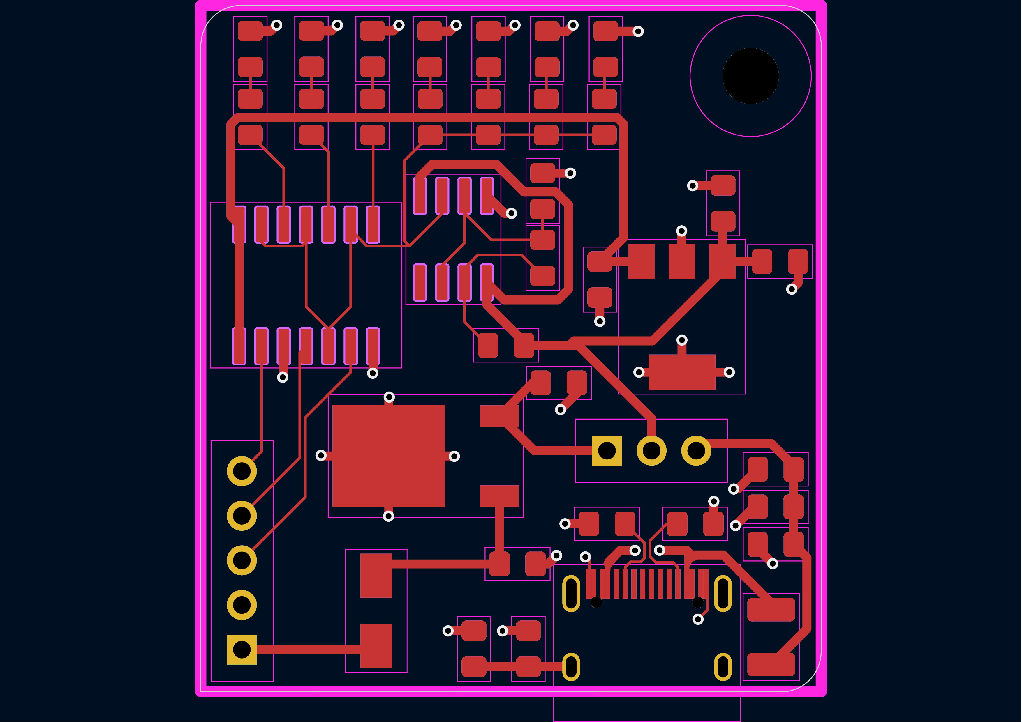
Pcb wrkbk brd1 is an open-source printed circuit board by mohd-hani, from the mohd-hani/555-Timer-Project repository on GitHub. It is a 2-layer board of 35.3 × 39.1 mm with 41 parts on 34 nets, routed with 216 tracks and 35 vias.
It is built around the SA555DR-MS, SN74ALVC14NSR and 0.1UF 50V 5*11. Its parts include 12 resistors, 10 capacitors, 8 diodes, 4 ICs and 3 connectors.

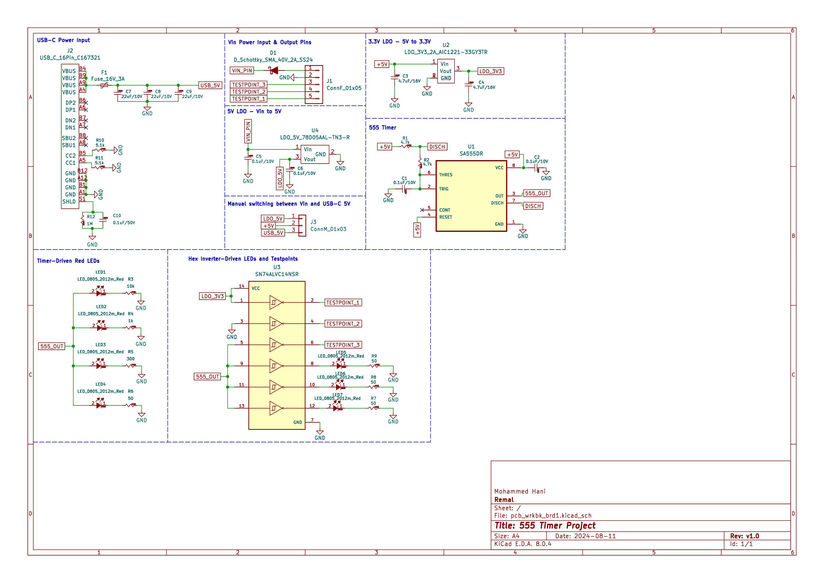
This project is a KiCad-designed circuit board centered around the 555 timer IC, which serves as a versatile timer and oscillator. The board is powered by a 5V power supply and can be fed through either a USB C connector or a voltage source connected to the Vin pin. The design allows for manual switching between these two power inputs.
Power Supply:
555 Timer:
Hex Inverter IC:
Test Points:
To use the board:
Power Connection:
LED Display:
Testing:
| Qty | Value | Footprint | References |
|---|---|---|---|
| 7 | LED_0805_2012m_Red | Remal_KiCadLib:LED_0805_2012m_Red | LED1, LED2, LED3, LED4, LED5, LED6, LED7 |
| 4 | 50 | Remal_KiCadLib:R_0805_2012m | R6, R7, R8, R9 |
| 3 | 0.1uF/10V | Remal_KiCadLib:C_0805_2012m | C1, C5, C6 |
| 3 | 22uF/10V | Remal_KiCadLib:C_0805_2012m | C7, C8, C9 |
| 2 | 4.7k | Remal_KiCadLib:R_0805_2012m | R1, R2 |
| 2 | 4.7uF/16V | Remal_KiCadLib:C_0805_2012m | C3, C4 |
| 2 | 5.1k | Remal_KiCadLib:R_0805_2012m | R10, R11 |
| 1 | 0.01uF/10V | Remal_KiCadLib:C_0805_2012m | C2 |
| 1 | 0.1uF/50V | Remal_KiCadLib:C_0805_2012m | C10 |
| 1 | 10k | Remal_KiCadLib:R_0805_2012m | R3 |
| 1 | 1M | Remal_KiCadLib:R_0805_2012m | R12 |
| 1 | 1k | Remal_KiCadLib:R_0805_2012m | R4 |
| 1 | 300 | Remal_KiCadLib:R_0805_2012m | R5 |
| 1 | ConnF_01x05 | Remal_KiCadLib:PinSocket_1x05_P2.54mm_Vertical | J1 |
| 1 | ConnM_01x03 | Remal_KiCadLib:PinHeader_1x03_P2.54mm_Vertical | J3 |
| 1 | D_Schottky_SMA_40V_2A_SS24 | Remal_KiCadLib:D_SMA | D1 |
| 1 | Fuse_16V_3A | Remal_KiCadLib:Fuse_1210_3225m | F1 |
| 1 | LDO_3V3_2A_AIC1221-33GY3TR | Remal_KiCadLib:SOT-223 | U2 |
| 1 | LDO_5V_78D05AAL-TN3-R | Remal_KiCadLib:TO-252-2 | U4 |
| 1 | LOGO | fp_meowlibrary:black_cat | G*** |
| 1 | LOGO | LOGO | G*** |
| 1 | SA555DR | fp_meowlibrary:SOIC127P599X175-8N | U1 |
| 1 | SN74ALVC14NSR | fp_meowlibrary:SOP127P780X200-14N | U3 |
| 1 | USB_C_16Pin_C167321 | Remal_KiCadLib:USB_C_16Pin_C167321 | J2 |
The 40 most common of 41 parts.
It measures 35.3 × 39.1 mm and has 2 copper layers, 1.6 mm thick.
41 parts, built around the SA555DR-MS, SN74ALVC14NSR and 0.1UF 50V 5*11. The full list of its parts is on this page, with links to each part's symbol and footprint where PCBKit's library has them.
From the mohd-hani/555-Timer-Project repository on GitHub, at the commit this page was made from: the board is pcb_wrkbk_brd1.kicad_pcb and its schematic pcb_wrkbk_brd1.kicad_sch. PCBKit opens the board in the browser, with nothing to install.
Its repository states no licence, so its author keeps all rights: ask mohd-hani before reusing the design.
Shaxzodm2611/4-bit-Adder-Interface-Board
A custom PCB designed to mimic the function of a CPU. Entirely made from discrete logic ICs.


EnriqueNeyra/Aeroq
An Indoor Air Quality Monitor Powered by ESP32, SCD40, and SEN54

EnriqueNeyra/aether
All-in-one home air quality monitor measuring Temp, Humidity, CO2, VOCs, Particulate Matter, and NOx. Powered by ESP32-C3 running esphome, and built with Home Assistant integration


CuriousMotor/Onyx-Stepper-Motherboard
The successor of the iconic Arduino-CNC-shield


db-electronics/triple-bypass-kicad
An audio and video bypass circuit for the Sega Genesis