2 layers18 × 19 mm

 mofosyne/roTec_pcb17
A low-cost nrf52 device, targeting cases that supports rotary encoder. Forked from jtljac's take on faketec v5
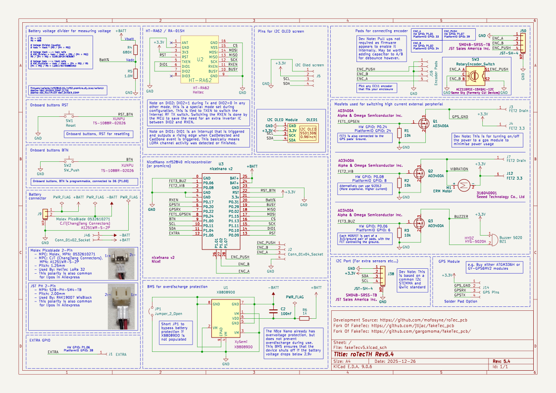
FakeTecv5 is an open-source printed circuit board by mofosyne, from the mofosyne/roTec_pcb repository on GitHub, published under the CERN-OHL-P-2.0 licence. It is a 2-layer board of 25.4 × 52.1 mm with 35 parts on 33 nets, routed with 348 tracks and 65 vias.
It is built around the XB8089D0, AO3400A and SM04B-SRSS-TB, with the HYG-5020A, A1251WR-S-2P and TS-1088R-02026 among its other parts. Its parts include 13 connectors, 6 resistors, 3 ICs, 3 transistors and 2 switches. It belongs with the nRF52 and nRF5x boards of this library.


Through Hole Version
| Front | Back |
|---|---|
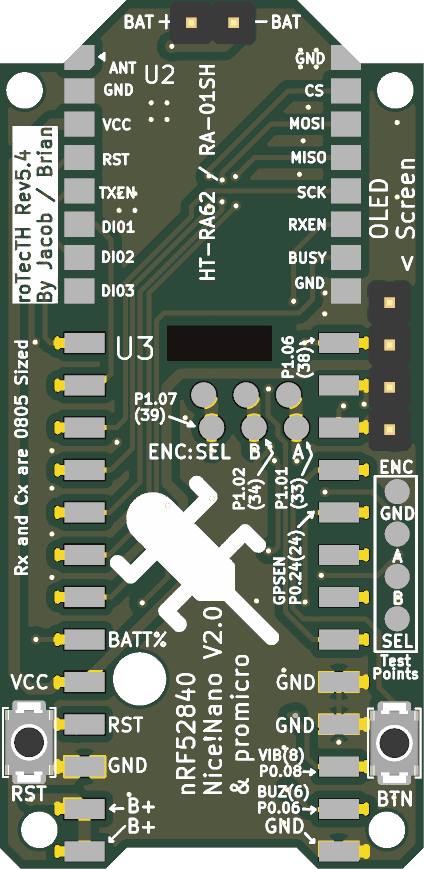 | 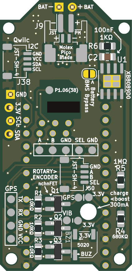 |
You may also want to manufacture EC11 Rotary Encoder Horizontal Breakout Board, so you can more easily wire the rotary encoder to the roTec via a JST-SH-4 cable.
| Qty | Value | Footprint | References |
|---|---|---|---|
| 3 | , , | ||
| 3 | 10k | Resistor_SMD:R_0805_2012Metric_Pad1.20x1.40mm_HandSolder | R1, R2, R3 |
| 3 | AO3400A | Package_TO_SOT_SMD:SOT-23_Handsoldering | Q1, Q2, Q3 |
| 2 | FET2 3,3 | faketec:SMD_PAD_1x01 | J4, J12 |
| 2 | FET2 Drain | faketec:SMD_PAD_1x01 | J3, J7 |
| 2 | JST-SH-4 | Connector_JST:JST_SH_SM04B-SRSS-TB_1x04-1MP_P1.00mm_Horizontal | J38, J50 |
| 1 | 1.0M | Resistor_SMD:R_0805_2012Metric_Pad1.20x1.40mm_HandSolder | R5 |
| 1 | 100nF | Capacitor_SMD:C_0805_2012Metric_Pad1.18x1.45mm_HandSolder | C2 |
| 1 | 1k | Resistor_SMD:R_0805_2012Metric_Pad1.20x1.40mm_HandSolder | R6 |
| 1 | 680K | Resistor_SMD:R_0805_2012Metric_Pad1.20x1.40mm_HandSolder | R4 |
| 1 | Buzzer 5020 | faketec:Buzzer_5020 | BZ1 |
| 1 | Conn_01x02_Socket | faketec:wirebond battery header | J46 |
| 1 | Conn_01x04_Socket | faketec:SMD_PAD_1x04 | J2 |
| 1 | EXTRA | faketec:SMD_PAD_1x01 | J1 |
| 1 | Encoder Pads | faketec:SMD_PAD_1x05 | J16 |
| 1 | GPS Pins | faketec:SMD_PAD_1x04 | J14 |
| 1 | HT-RA62 | faketec:HT-RA62 | U2 |
| 1 | I2C Oled screen | faketec:OLED_PinHeader_1x04_P2.54mm_Vertical_Friction_Fit | J5 |
| 1 | Jumper_2_Open | Jumper:SolderJumper-2_P1.3mm_Open_RoundedPad1.0x1.5mm | JP1 |
| 1 | Molex PicoBlade 0532610271 | faketec:Combined_Battery_Connector_Molex_PicoBlade_P1.00_And_JST_PH_2.00mm | J9 |
| 1 | Reset | faketec:SW_Push_SPST_NO_Alps_SKRK | SW1 |
| 1 | SW_Push | faketec:SW_Push_SPST_NO_Alps_SKRK | SW2 |
| 1 | XB8089D0 | Package_SO:SOIC-8-1EP_3.9x4.9mm_P1.27mm_EP2.41x3.3mm | U1 |
| 1 | nice!nano v2 | faketec:NICE!NANO and pro-micro V2_2 SMD_And_Through_Hole | U3 |
The 33 most common of 35 parts.
It measures 25.4 × 52.1 mm and has 2 copper layers, 1.6 mm thick.
35 parts, built around the XB8089D0, AO3400A, SM04B-SRSS-TB and HYG-5020A. The full list of its parts is on this page, with links to each part's symbol and footprint where PCBKit's library has them.
From the mofosyne/roTec_pcb repository on GitHub, at the commit this page was made from: the board is Circuit_Through_Hole/fakeTecv5.kicad_pcb and its schematic Circuit/fakeTecv5.kicad_sch. PCBKit opens the board in the browser, with nothing to install.
Its repository publishes it under the CERN-OHL-P-2.0 licence: you may reuse it on that licence's terms (keep the author's notice, and for a copyleft licence share your changes alike).

kolmeto1sta3-akk/amplifier-pcb
Библиотека вынесена в отдельный репозиторий my-kicad-library и подключена как сабмодуль в папку library/.

shadowpho/esp32-sensor
ESP32-S2 host, HDC2080 temp/humidity sensor with optional display.


mikechristiansen/GxAirCom_E290
GxAircom aims to be a complete and open source implementation of the FANET+ (Fanet + Flarm) protocol running on readily available cheap lora modules and interfacing with mobile phones via Bluetooth.


GuzziFlipFlops/ESP32-Walkie-Talkie
An open source ESPNOW based walkie talkie with a 600 meter tested distance, with an OLED and multiple buttons to interact with