2 layers58.4 × 44.4 mm
Twilight
harry48225/twilight
An automated roller blind opener. Using an esp32 runing micropython.
27 parts

 mmatthe/hexa-switch
This project is a custom-designed printed circuit board (PCB) for a Tasmota-compatible IoT device based on the ESP32 microcontroller. It allows switching of 6 loads, with each channel capable of handling up to 2 Amps.
Hexa switch is an open-source printed circuit board by mmatthe, from the mmatthe/hexa-switch repository on GitHub. It is a 2-layer board of 56.3 × 55 mm with 49 parts on 50 nets, routed with 286 tracks and 32 vias.
It is built around the ESP32-WROOM-32, TSR 1-2433 and IRLML0030. Its parts include 13 diodes, 9 resistors, 6 transistors, 4 capacitors and 2 ICs. It belongs with the ESP32 boards of this library.


This project is a custom-designed printed circuit board (PCB) for a Tasmota-compatible IoT device based on the ESP32 microcontroller. It allows switching of 6 loads, with each channel capable of handling up to 2 Amps. The device contains a real-time clock such that the device can also run on an independent time base.
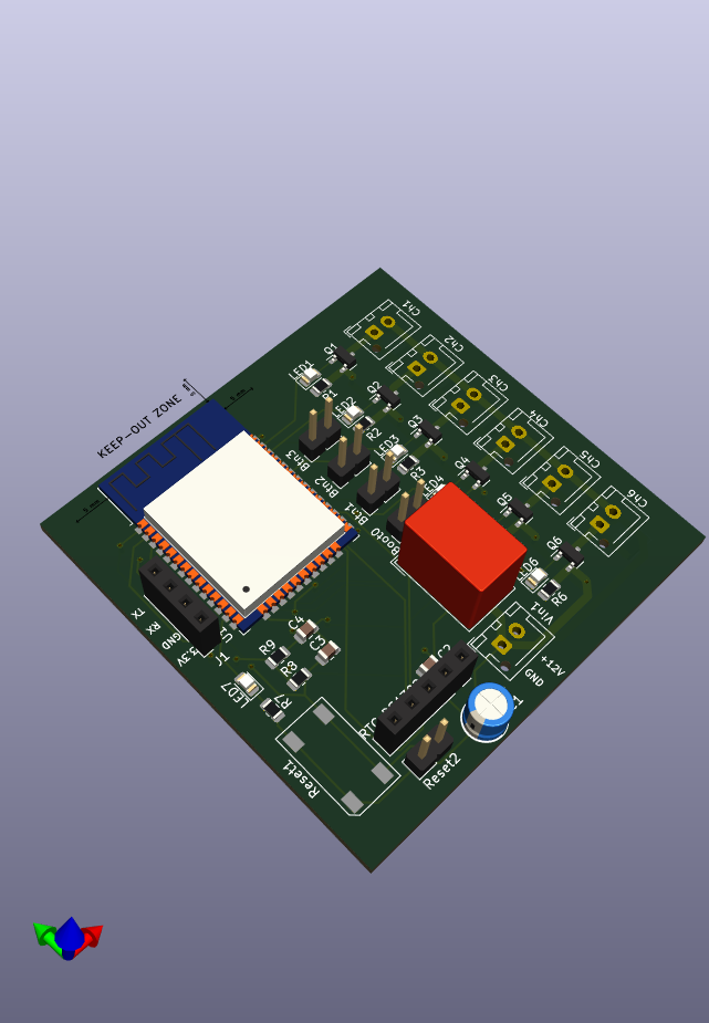
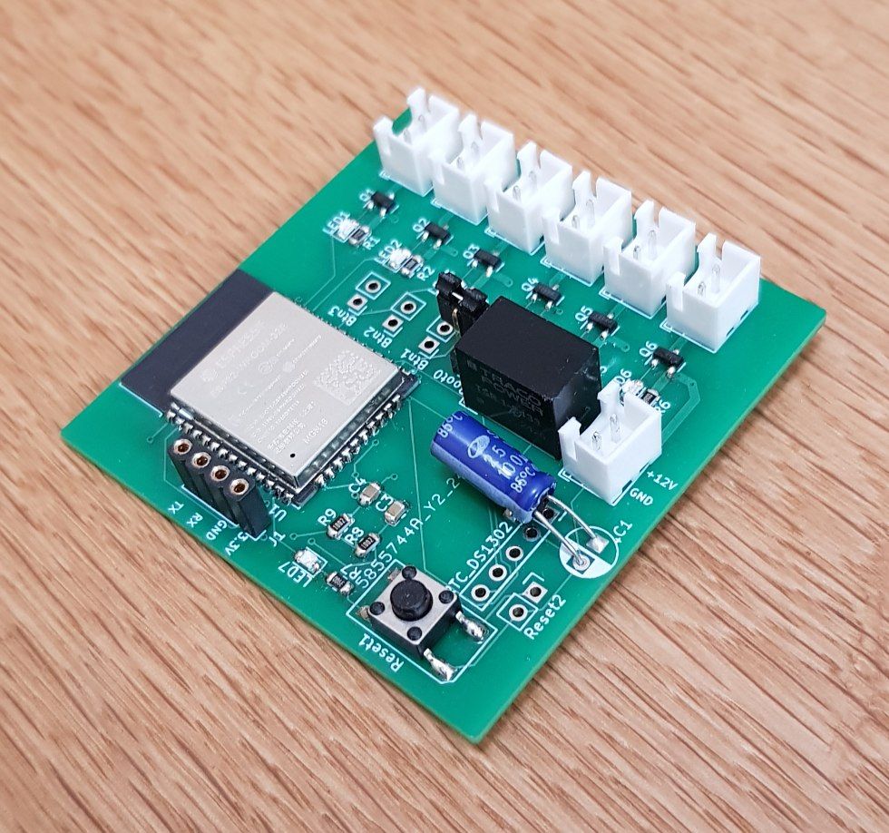
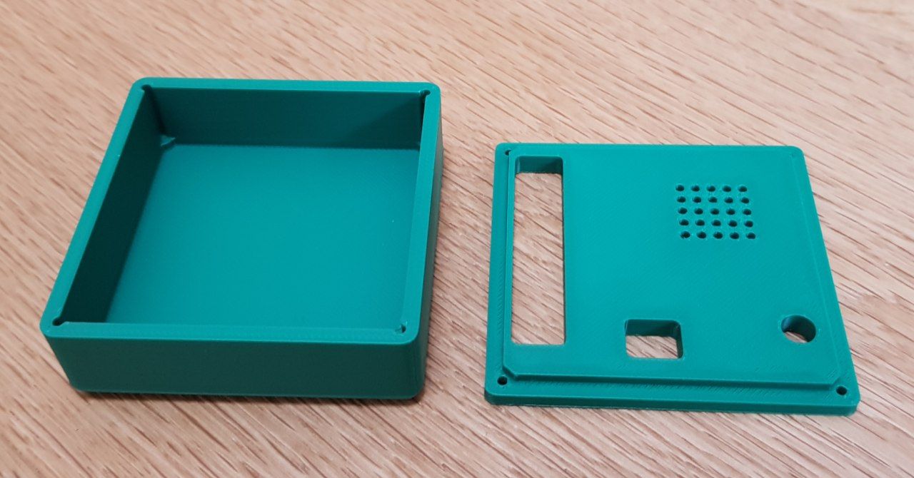
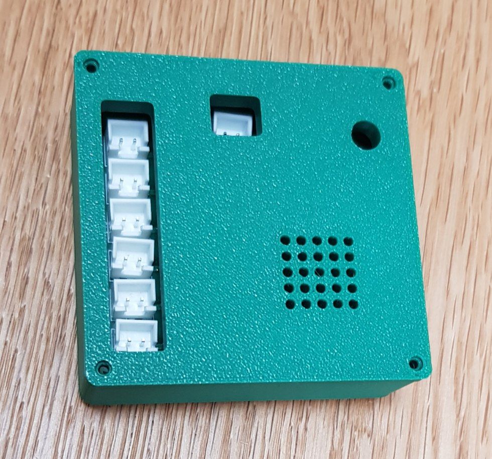
I use it for switching on and off 12V valves for watering plants in the garden. It can also be used to switch relays and contactors to switch larger powers.
This project is released under the MIT License.
| Qty | Value | Footprint | References |
|---|---|---|---|
| 7 | 270 | Resistor_SMD:R_0805_2012Metric | R1, R2, R3, R4, R5, R6, R7 |
| 7 | LED | LED_SMD:LED_0805_2012Metric | LED1, LED2, LED3, LED4, LED5, LED6, LED7 |
| 6 | Conn_01x02_Pin | Connector_JST:JST_XH_B2B-XH-AM_1x02_P2.50mm_Vertical | Ch1, Ch2, Ch3, Ch4, Ch5, Ch6 |
| 6 | D | Diode_SMD:D_SOD-123 | D1, D2, D3, D4, D5, D6 |
| 6 | IRLML0030 | Package_TO_SOT_SMD:SOT-23 | Q1, Q2, Q3, Q4, Q5, Q6 |
| 3 | 100n | Capacitor_SMD:C_0805_2012Metric | C2, C3, C4 |
| 3 | Conn_01x02_Pin | Connector_PinHeader_2.54mm:PinHeader_1x02_P2.54mm_Vertical | Btn1, Btn2, Btn3 |
| 2 | 10k | Resistor_SMD:R_0805_2012Metric | R8, R9 |
| 1 | 22u | Capacitor_THT:CP_Radial_D5.0mm_P2.50mm | C1 |
| 1 | Conn_01x05 | Connector_PinSocket_2.54mm:PinSocket_1x05_P2.54mm_Vertical | RTC_DS1302 |
| 1 | ESP32-WROOM-32 | RF_Module:ESP32-WROOM-32 | U1 |
| 1 | IO0 | Connector_PinHeader_2.54mm:PinHeader_1x02_P2.54mm_Vertical | Boot0 |
| 1 | Reset | footprints:Reichelt 9315 | Reset1 |
| 1 | Reset | Connector_PinHeader_2.54mm:PinHeader_1x02_P2.54mm_Vertical | Reset2 |
| 1 | TSR_1-2433 | Converter_DCDC:Converter_DCDC_TRACO_TSR-1_THT | U3 |
| 1 | UART | Connector_PinSocket_2.54mm:PinSocket_1x04_P2.54mm_Vertical | J1 |
| 1 | Vin | Connector_JST:JST_XH_B2B-XH-AM_1x02_P2.50mm_Vertical | Vin1 |
It measures 56.3 × 55 mm and has 2 copper layers, 1.6 mm thick.
49 parts, built around the ESP32-WROOM-32, TSR 1-2433 and IRLML0030. The full list of its parts is on this page, with links to each part's symbol and footprint where PCBKit's library has them.
From the mmatthe/hexa-switch repository on GitHub, at the commit this page was made from: the board is schematic/schematic.kicad_pcb and its schematic schematic/schematic.kicad_sch. PCBKit opens the board in the browser, with nothing to install.
Its repository states no licence, so its author keeps all rights: ask mmatthe before reusing the design.
harry48225/twilight
An automated roller blind opener. Using an esp32 runing micropython.


JokerIsMyBae/AirQualityHoboken
Applied IoT project voor luchtkwaliteitsmetingen in Hobokense Polder

shm-dmitry/air-detector
Air status sensor with hass integration and fan control


punkfab/pcb-corpus
235 real KiCad boards from open-source hardware repositories, prepared as a placement and routing benchmark

shm-dmitry/auto_close_window
This IOT project allows you to open and close your window from any smart house. For example - you can setup rules like a "If night and noise greater then expected -> close window" and "Noise reduced -> open window"

Staacks/there.oughta.be
Projects featured on my blog at https://there.oughta.be