


2 layers97.2 × 59.1 mm
ArmLEDsPrototype
hackclub/OnBoard
💡 Join 1,000 teenagers and make your first PCB with a $100 grant!
35 parts915

 mmassico/window_air_vent
Sliding window air exchanger without heat recovery (3D models)
Window vent ctrl is an open-source printed circuit board by mmassico, from the mmassico/window_air_vent repository on GitHub, published under the CERN-OHL-P-2.0 licence. It is a 2-layer board of 70 × 50 mm with 35 parts on 49 nets, routed with 463 tracks and 17 vias.
Its parts include 10 resistors, 8 connectors, 2 ICs, 1 capacitor and 1 diode. It belongs with the ESP32 boards of this library.
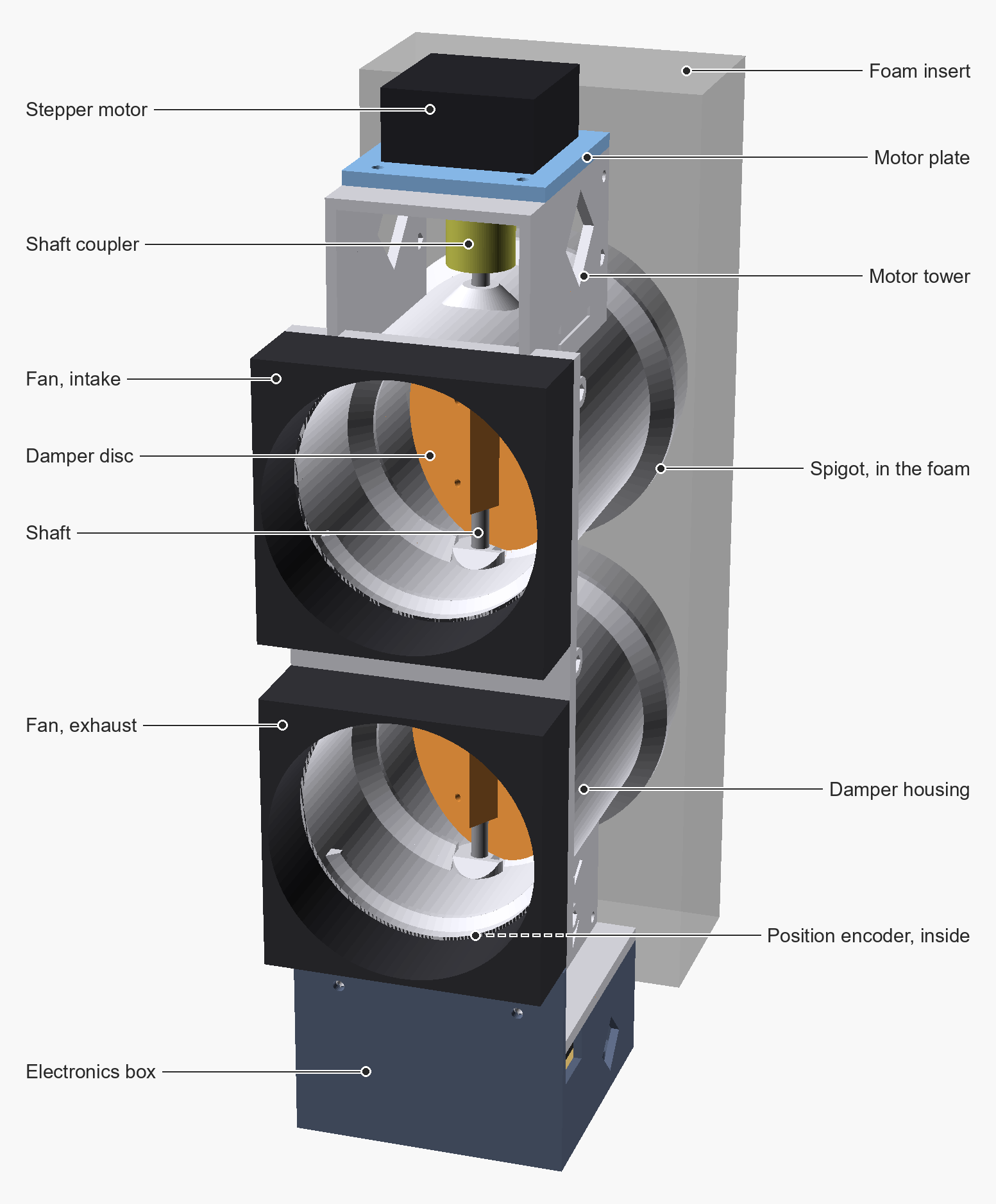
A demand-controlled window ventilator for one room. Two 80 mm fans move air through a foam window insert: one brings fresh air in, the other exhausts stale air. A single butterfly-damper housing closes both holes with one shaft, turned by a silent stepper motor. An ESP32 reads a CO₂ sensor and runs the fans and the damper.
There is no heat recovery: every litre of air exhausted is lost heat. In exchange it is simple, cheap and automatic. See the estimates below.
Status: prototype, running in a window. The complete unit is installed in a window, on the controller PCB and the web application, and ventilates on its own from its CO₂ reading. It closes when it's loud outside, using a microphone listening through a tube in the foam. Every printed part has been printed and test-fitted (housing, discs, motor plate, magnet cap, electronics box, tube spacer, louvers), and several were refined from those prints: the shaft holes' sacrificial fins, the box's back tabs, the louvers' snap-in combs, and the discs' seats. The lip seals are installed and tested: with the 1.6 mm neoprene, the closed discs now press evenly on the foam all round, after two rounds of tuning the discs' seats (the housing stayed as printed). The housing was then reprinted with flat shaft bosses and the discs with matching flats: the gap at the bosses is gone (the first, curved bosses left 0.3 to 0.75 mm), and the reprinted electronics box fits too, its back tabs and the notches for the fan's rubber bumpers included; the tabs make mounting it on the housing much easier. The shaft holes' sacrificial fins work as intended: no warping, and they drill out easily. The lip foam cutting guides are printed and tested: cutting the foam with them is much easier, faster and more accurate than with the paper templates. The foam-free
disc_nofoamis checked in CAD but not tested yet. Its CO₂ reading agrees with a calibrated meter within the sensor's tolerance. What's still to come is time: it has only just gone in, so it hasn't seen a season yet. The geometry is also checked in CAD (closed solids, the discs swing freely, the lips stop them).
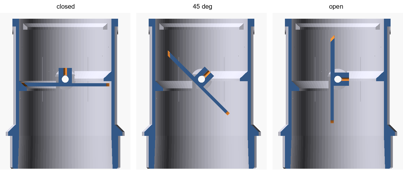
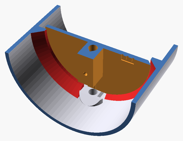
disc_nofoam), one on each side of the shaft. One lip is flat; the other is a 45° cone, and the half of the disc that closes against it (engraved B) has a matching 45° bevel, so neither prints as a flat overhang.

| Airflow (each way) | CO₂ in the room | Heat lost at −20 °C outdoors |
|---|---|---|
| 5 L/s (11 CFM) | ~1000 ppm | ~250 W |
| 8 L/s (17 CFM) | ~800 ppm | ~400 W |
| 11 L/s (23 CFM) | ~700 ppm | ~540 W |
At 8 L/s, roughly 10 hours a day over a cold-climate heating season (about 200 days, electricity at 7–11 ¢/kWh), the lost heat costs about $35–45. The fans use about 1 W each.
| Part | Thumbnail | Qty | Description | Size (mm) | Print orientation |
|---|---|---|---|---|---|
body | 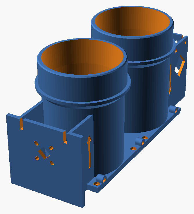 | 1 | Housing: two ducts with the damper lips, drip dams and shaft bosses, spigots for the foam, fan plate, motor frame and encoder plate | 90 × 241 × 114 | Fan plate on the bed, no supports |
disc | 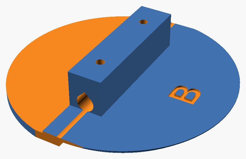 | 2 | Butterfly damper disc, clamped to the shaft by two M3 grub screws; the half engraved B has a 45° bevel on its rim. Its seats are relieved for the 1.6 mm lip foam, and its two shaft ends are cut flat to face the bosses | 67 × 65 × 14 | Plate on the bed, hub up |
disc_nofoam | 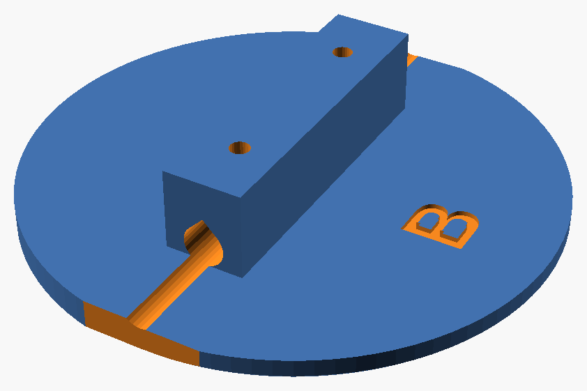 | (2) | Instead of disc, for lips without foam: half A is 3.6 mm thick and half B's bevel is smaller, so both seats close to 0.3 mm from the bare lips | 67 × 65 × 14 | Plate on the bed, hub up |
motor_plate | 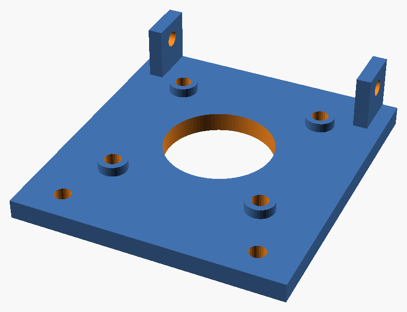 | 1 | The motor screws to it on the bench; it then sits on top of the housing: two screws in front of the motor, and two tabs at the back, down through the frame and screwed to the tower walls | 56 × 61 × 15 | Top face on the bed, tabs up |
magnet_cap | 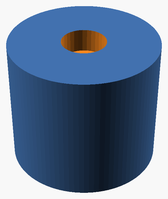 | 1 | Holds the encoder magnet on the bottom end of the shaft; one M3 grub screw, height adjustable ±1 mm | 14 × 14 × 12 | Bore down |
ebox | 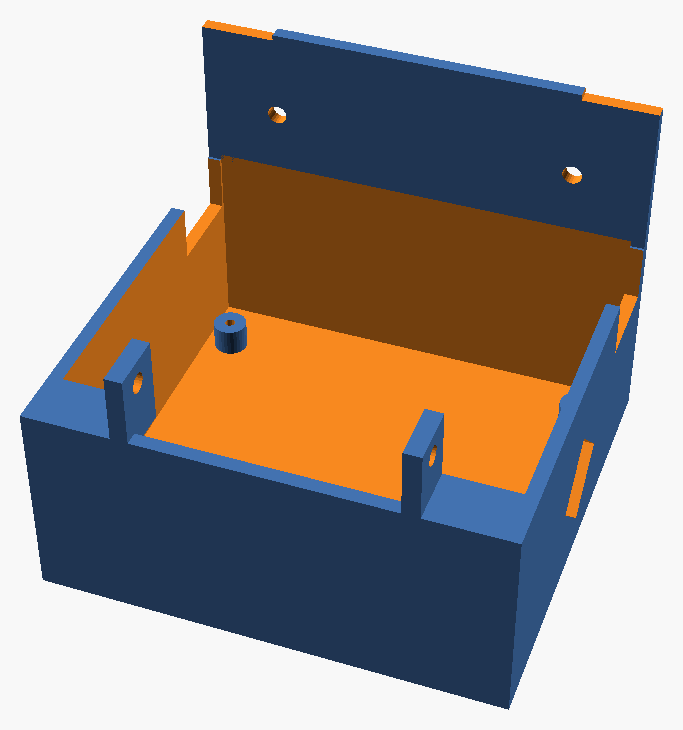 | 1 | Electronics box under the housing; its front wall also covers the front of the bottom bay, and two back tabs screw to the bay walls | 80 × 76 × 64 | Floor on the bed |
tube_spacer | 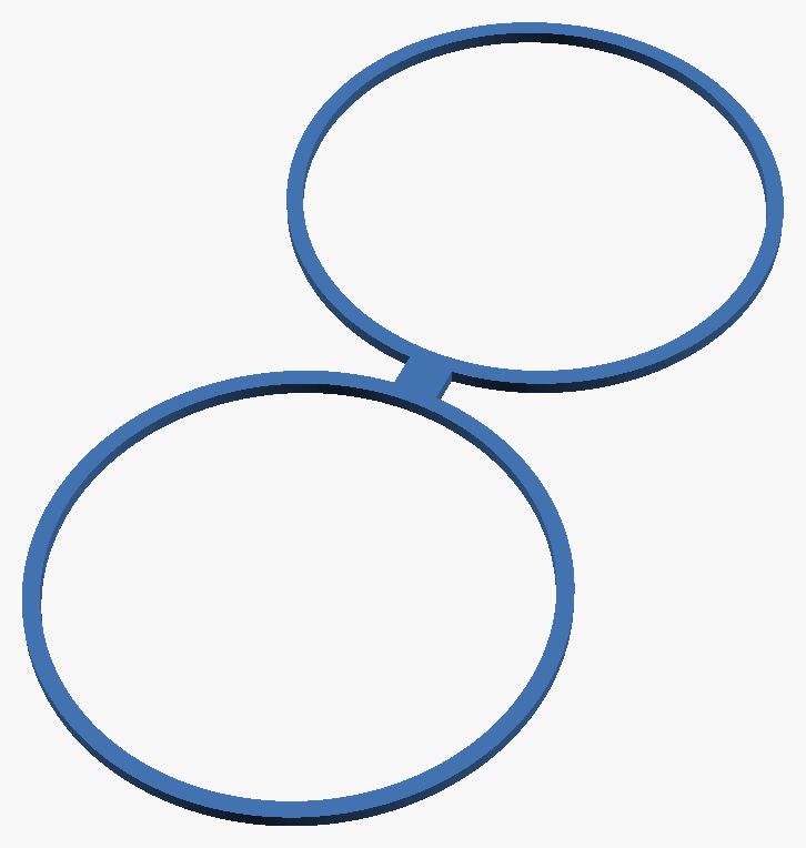 | 1 | Flat "8" over both spigots, against the stop rings and squeezed by the foam: it holds the spigots' ends at their spacing, so foam holes slightly off 96 mm can't bend the ducts and bind the shaft. The vent sits 2.5 mm further out of the foam | 90 × 186 × 2.5 | Flat |
screen_frame | 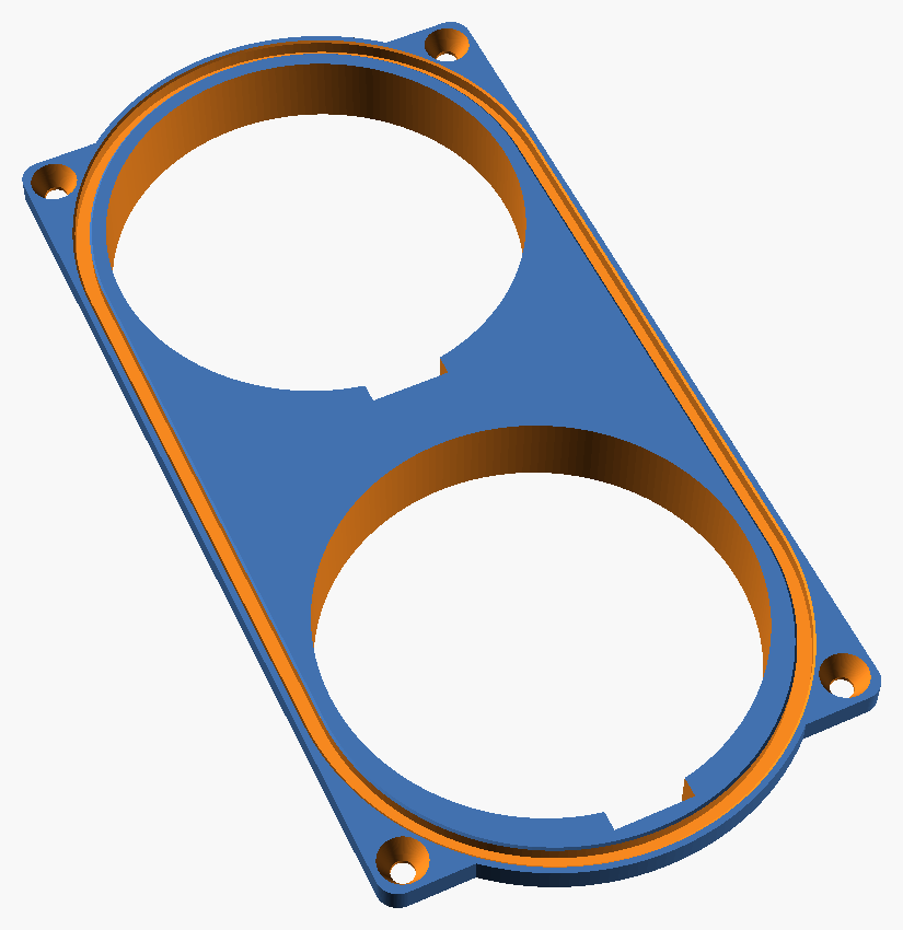 | 1 | Insect screen frame on the foam's outdoor face: the mesh is pressed into a groove around both holes, two sleeves plug into the holes, four screws in the corners, a drain at the bottom of each hole | 94 × 193 × 15 | Outdoor face on the bed, sleeves up |
tray | 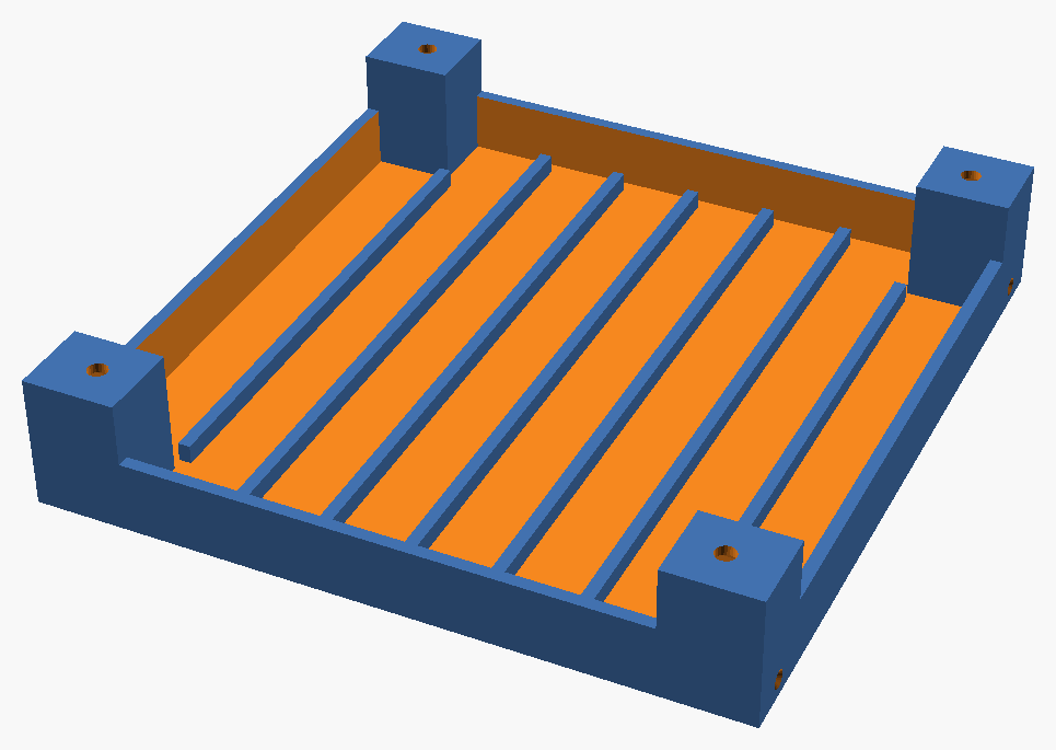 | (1) | Optional drip tray on the window ledge, under the whole unit: the electronics box stands on ribs above its floor, and an adjustable leg in each corner levels it | 112 × 115 × 22 | Floor on the bed |
tray_feet | 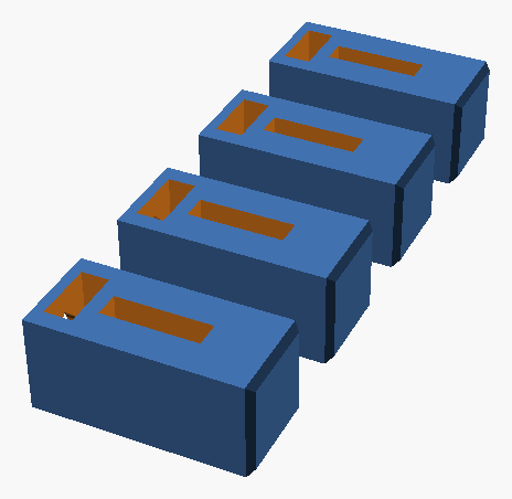 | (4) | The tray's feet, one per leg: each slides in its post's socket, carries a captive M3 nut, and has a groove for the M2 stop | 9 × 9 × 20 each | On its side, the nut's slot up |
Housing and discs must match. The housing's shaft bosses have flat inner faces, and the discs have matching flats. A housing printed before this change (curved boss faces) needs the earlier discs: set flat_boss = false in cad/window_vent.scad and export disc (or disc_nofoam). A disc with flats leaves a 1.6 mm gap at a curved boss, and a disc without them won't turn between flat bosses.
For a 180 mm printer (e.g. Bambu Lab A1 mini), print the housing in two halves instead of body. The cut runs midway between the two ducts, where only the fan plate joins them; a small splice plate behind the fan plate joins the halves again with four M3 screws, driven from the fan side in the band between the two fans. Each half prints like the full housing, in about half the time (roughly 5–6 h), so they can go on different days; use the same spool and profile for both.
| Part | Thumbnail | Qty | Description | Size (mm) | Print orientation |
|---|---|---|---|---|---|
body_top | 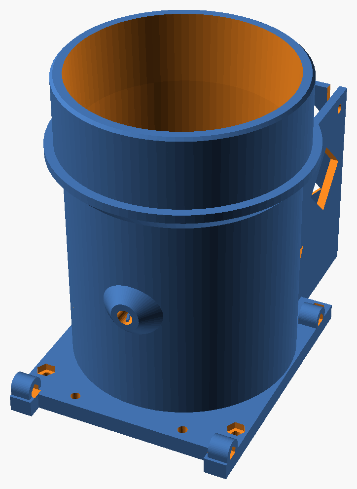 | 1 | Upper half: intake duct, upper fan, motor frame, and both middle tie-wrap anchors (whole) | 90 × 130 × 114 | Fan plate on the bed, no supports |
body_bottom | 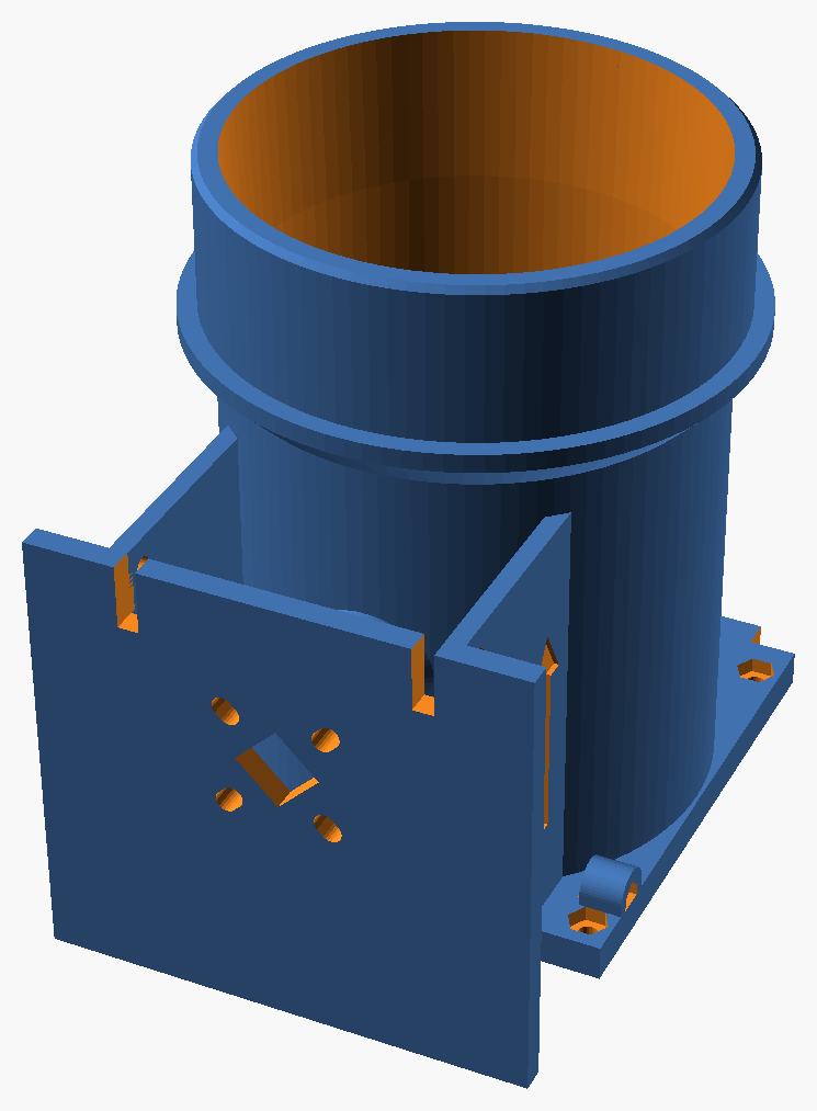 | 1 | Lower half: exhaust duct, lower fan, encoder plate; notched under the two middle anchors | 90 × 116 × 114 | Fan plate on the bed, no supports |
splice | 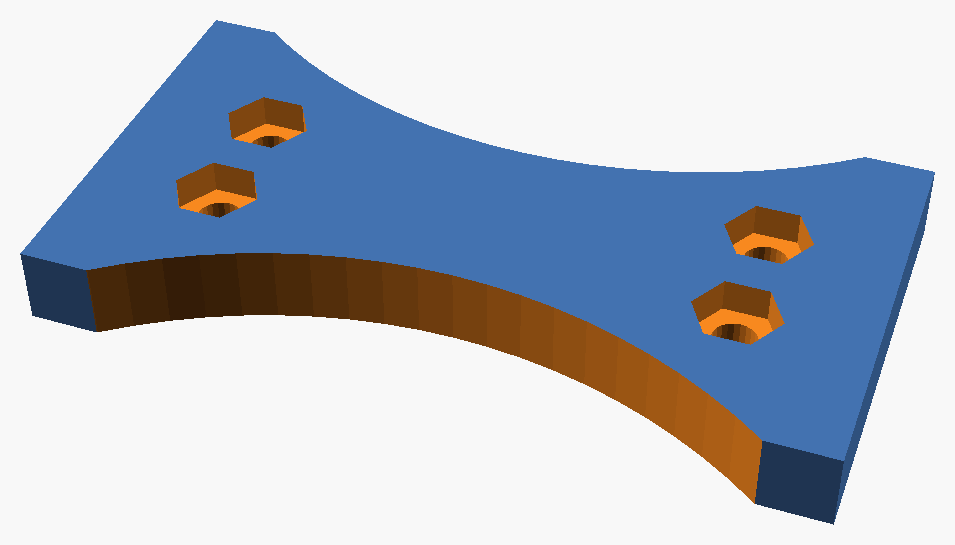 | 1 | Joins the halves behind the fan plate; four M3 nut pockets on its back | 60 × 32 × 6 | Flat, nut pockets up |
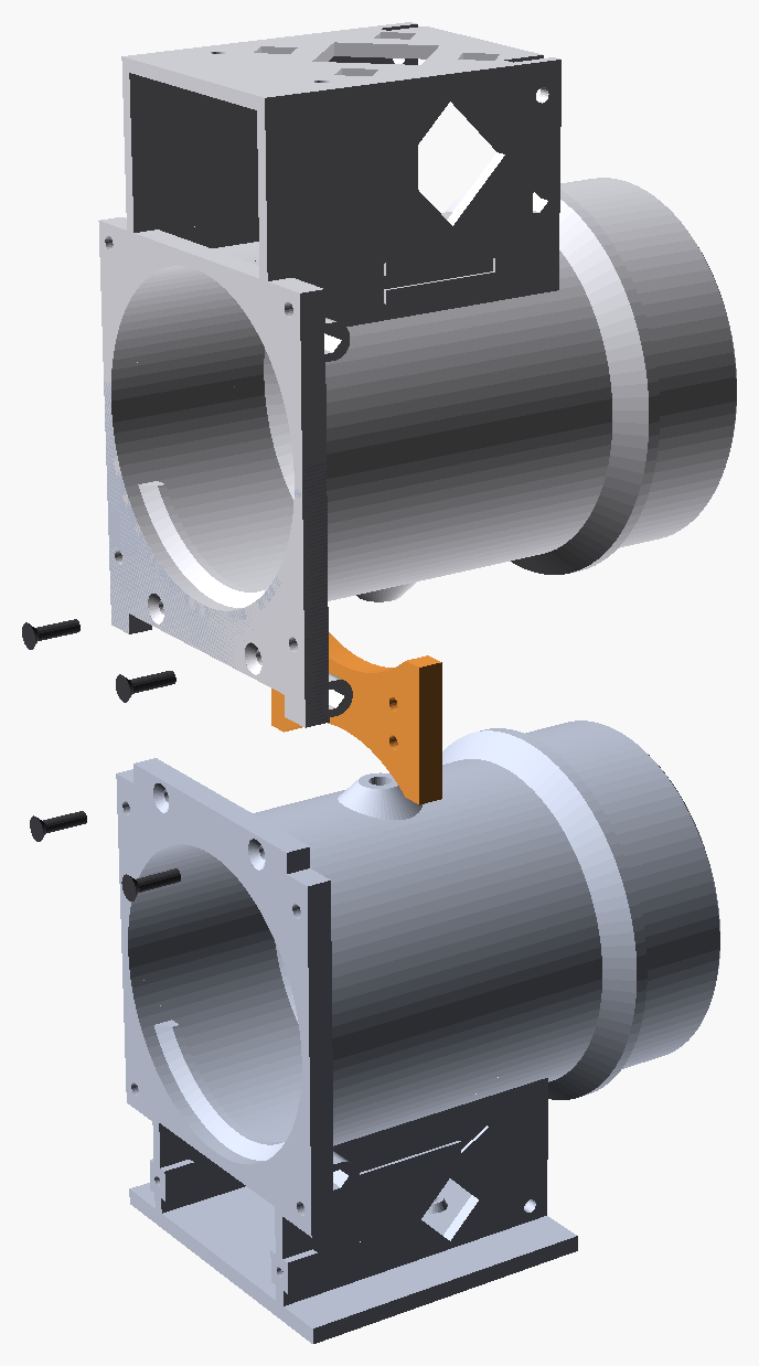
Optional test prints, before the housing. Print the small real parts first (discs, motor plate, magnet cap, about 1.5–2 h): they test the rod, the grub screws, the motor and the magnet. Then:
| Part | Thumbnail | Size (mm) | Time | What it tests |
|---|---|---|---|---|
fittest | 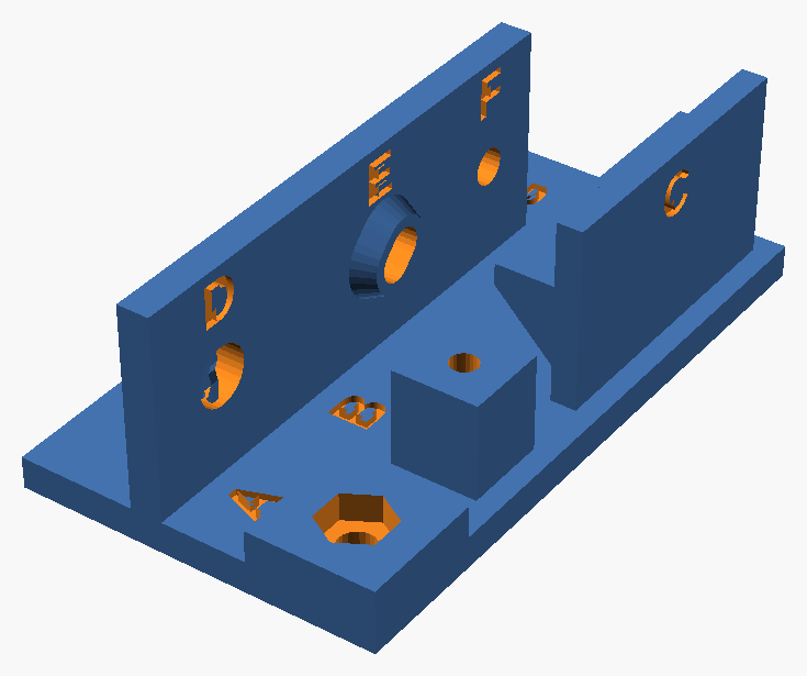 | 60 × 34 × 22 | about 20–30 min | The housing's printer-sensitive features, in its print orientation, engraved A to G (see below) |
oring_test | 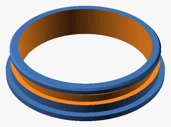 | Ø 90 × 18 | about 30 min | One spigot section (with an O-ring groove): push it into a test hole cut in a foam scrap, bare first; if it's loose, try it with an O-ring |
The fit-test coupon. It copies seven features of the housing that depend most on the printer: holes and a slot, a nut pocket, a pilot for self-tapping screws, the conical lip's 45° ledge and a countersink. Each is engraved with a letter, A to G. Print it with the housing's filament and settings, then check each feature against the table below: if one fails, adjust the slicer (or the hole sizes in the model) before starting the 9–12 hour housing print.
| Feature | Copied from | Pass if | |
|---|---|---|---|
| A | M3 hole + nut pocket | fan plate | the nut drops in and stays; an M3 screw passes freely |
| B | Ø 2.5 self-tapping pilot | the box cover bosses | an M3 screw cuts a firm thread without splitting the post |
| C | 5.6 mm ledge with a 45° underside (on the back of the plate) | conical lip B in each bore | the slope is smooth, not drooping or stringy |
| D | Ø 5.4 shaft hole, horizontal, with its sacrificial fin | bearing holes in the duct walls | the top of the hole stays round; after drilling the fin out (see below), the 5 mm rod turns freely |
| E | AS5600 diagonal slot (3.5 wide) on a 2 mm standoff | encoder plate | an M3 screw passes at both ends of the slot |
| F | M3 hole, horizontal | motor frame | an M3 screw passes freely |
| G | M3 hole with a 90° countersink, opening on the bed | split housing joint (body_top and body_bottom) | an M3 flat-head screw sits flush or just below the surface |
PETG. No support is needed anywhere: every face that looks down when printing (the lip B seat, the disc bevel, the boss sides, the O-ring grooves, the countersinks) slopes at 45° or less.
About 0.5 kg of PETG for one unit (about half a 1 kg spool), or roughly $12–17 at $25–35/kg.
| Part | Qty | Solid volume |
|---|---|---|
body | 1 | 282 cm³ |
disc | 2 | 2 × 12.7 = 25 cm³ (disc_nofoam: 2 × 14.7) |
motor_plate | 1 | 12.6 cm³ |
magnet_cap | 1 | 1.6 cm³ |
ebox | 1 | 47 cm³ |
tube_spacer | 1 | 4.5 cm³ |
screen_frame | 1 | 39 cm³ |
| Total | ≈ 412 cm³ |
The split housing (body_top 136 cm³, body_bottom 145 cm³, splice 8 cm³) adds about 7 cm³ (9 g).
fittest 12 cm³, oring_test 20 cm³, fin_test 3 cm³. The optional drill_guide adds 9 cm³ (11 g), and the optional lip foam cutting guides 9 cm³ (12 g): foam_guide_a 4.3 cm³, foam_guide_b 5.0 cm³. The screen frame's screen_test adds 6 cm³ (7 g). The optional drip tray adds 46 cm³ (58 g): tray 41 cm³, tray_feet 5 cm³, and its tray_test 5 cm³ (6 g).Most parts are thin, so the number of walls (Bambu Studio: Strength → Wall loops) matters more than the infill percentage: with enough walls, the thin parts come out solid and the infill only fills the few thicker zones.
| Part | Wall loops | Sparse infill | Why |
|---|---|---|---|
body (or body_top and body_bottom) | 4 | 25 % | Thin walls everywhere; the infill only reaches the thick zones (bosses, spigot roots, fan plate). No supports: a sacrificial fin holds up the top of each of its four shaft holes (see below) |
disc (or disc_nofoam) | 5 | 40 % | The grub screws thread into the hub: 5 loops leave about 2 mm of solid plastic around each hole |
motor_plate | 5 | 40 % | Screw holes, bosses and tabs under clamping load |
magnet_cap | 100 % | Tiny, with a grub screw in it: print it solid | |
splice | 5 | 40 % | Joins the two halves: nut pockets and countersunk screws |
ebox | 4 | 15–20 % | No real loads; a 4th wall (same print time) makes the walls around the screw holes stronger |
tube_spacer | 100 % | Thin rings (3 mm wide, 2.5 mm thick) that must not stretch: print it solid | |
screen_frame, screen_test | 4 | 25 % | Thin plate and sleeves: 4 walls print them nearly solid, so the groove's walls hold the spline |
tray, tray_feet, tray_test | 4 | 25 % | The 5 bottom layers below keep the tray's 1.6 mm floor watertight; 4 walls make the posts and feet nearly solid |
fittest, oring_test | 4 | 25 % | As the housing, so they test what the housing will be |
drill_guide | 4 | 40 % | Small; 4 walls make the bushings solid |
foam_guide_a, foam_guide_b | 4 | 40 % | Thin plate and rib: 4 walls print them solid, so they stay flat and stiff |
louver_chassis | 3 | 20 % | Light load |
louver_blade | 3 | 15 % | Thin and light; their pins come out solid anyway |
louver_link_nopad (or louver_link), louver_retainer | 100 % | Small and thin |
fin_t in the model, 0 for none) standing on the bottom of the hole and holding up its top, with 1.5 mm clear at each end. After printing, drill the fins out by hand with a 5.2 mm bit (13/64 in, the one used on the housing; 5.4 or 5.5 mm also works): the bit enters the clear end first, sits square, and cuts the fin easily. Tested on the housing: the holes come out round, with no warping, and the 5 mm rod turns freely. Feature D of fittest is the same hole with the same fin, and fin_test is a 10-minute block with two of them.Prices: Amazon.ca, October 2026, before taxes. Packs of two leave a spare.
| Item | Qty | Notes | Price (CAD) |
|---|---|---|---|
| 80 mm PWM fan, ≥ 2 mm H₂O static pressure | 2 | Noctua NF-A8 PWM (2.37 mm H₂O, 17.7 dB(A) max). Run at 30–60% | 2 × $24.95 |
| Stepper motor, NEMA 17 pancake | 1 | StepperOnline 17HS08-1004S (42 × 42 × 20 mm, 5 mm shaft, 13 N·cm). Any NEMA 17 fits the mount | $26.50 |
| TMC2209 stepper driver | 1 | StealthChop for silent moves; UART for StallGuard | $16.99 (pack of 2) |
| AS5600 magnetic encoder board + diametric magnet | 1 | Sold with the magnet (the kit: 23.3 × 22.8 mm board, 3.95 × 2 mm magnet). A 20 × 20 board with 15 mm hole spacing also fits: 4 × M3 × 12 + nuts onto standoff pads on the bottom plate. See the magnet note below | $12.69 (pack of 2) |
| ESP32-S3 dev board | 1 | Freenove ESP32-S3-WROOM Lite (FNK0099), the board the firmware's pinout is written for; other ESP32-S3-WROOM-1 boards work with a pin check. Flash it over USB on the bench; the final firmware updates over Wi-Fi | — |
| CO₂ sensor, NDIR | 1 | Sensirion SCD40 module (CO₂ + temperature + humidity, I²C). Not CCS811/SGP30 ("eCO₂" estimates) | $37.45 |
| DS18B20 temperature probe, waterproof | 1 (+1 optional) | Outdoor air: the 6 mm stainless probe on its cable goes through the foam insert, above the intake (template). A second one, indoors on an inside wall, is optional: the SCD40 already reads the room's temperature | — |
| Steel rod, 5 mm × 200 mm | 1 | Damper shaft. 200 mm fits as is, no cutting. If it is HSS (very hard), grind a small flat with a rotary tool where each disc and the coupler clamp, so the screws can't slip | $12.79 (pack of 2) |
| Flexible shaft coupler, 5–5 mm, 19 × 25 mm | 1 | $13.49 (pack of 2) | |
| M3 × 35 screws + M3 nuts | 8 each | Fans | — |
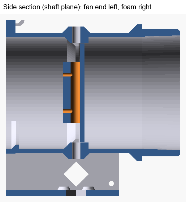
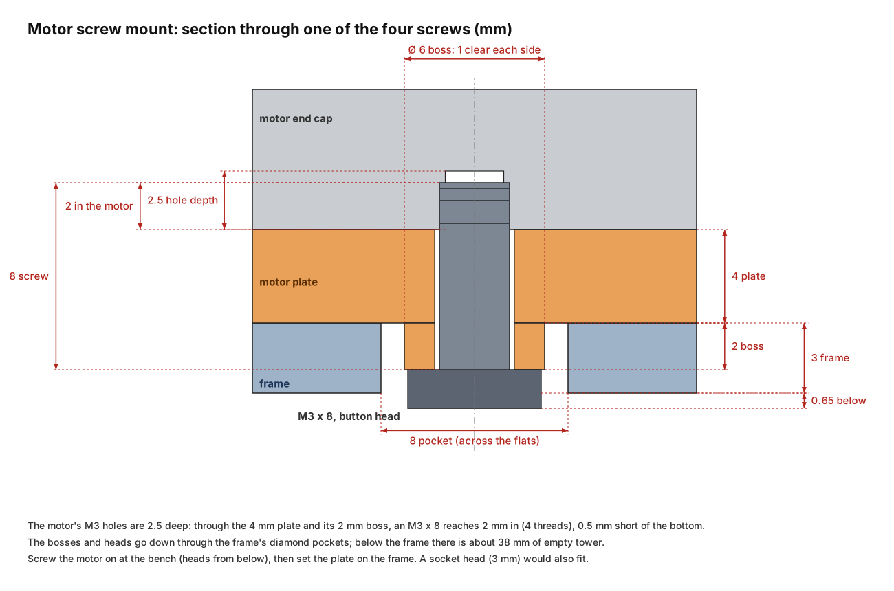
| M3 × 8 screws | 4 | Motor to motor plate, through the bosses under the plate. Not longer: the motor's holes are only 2.5 mm deep (section) | — |
| M3 × 10 (or M3 × 12) screws + M3 nuts | 6 each | Motor plate: two through the frame in front of the motor, two through the tower walls and the plate's back tabs. Electronics box: two through the bay walls and the box's back tabs | — |
| M3 grub screws, 6 mm (and one 4–5 mm) | 5 | Two 6 mm per disc, 24 mm apart along the hub, so the disc can't rock on the shaft (flush with the hub); one 4–5 mm in the magnet cap (a 6 mm one would stick out 1.5 mm). Self-tapping into the plastic | — |
| O-rings, 74 × 3 mm, nitrile 70A | 4 | Optional, and not needed by default: the plain Ø 83.7 spigots are a snug fit in the hole (83.3 mm with the 3-1/4 in hole saw). For a hole that comes out loose, set orings = true before printing the housing: two grooves per spigot, sized for this O-ring (about 6% stretch, 20% squeeze in an 83.3 mm hole) | $12.79 (pack of 10) |
| Insect screen kit: fibreglass mesh, 0.125 in screen spline, spline roller | 1 | Insect screen: a piece of mesh about 115 × 210 mm and about 50 cm of spline (or 3 mm O-ring cord, cut from the 74 × 3 O-rings above) | — |
| Countersunk screws, 8 mm head (3.5 mm high), about 25 mm long | 4 | Screen frame into the foam (4.25 mm holes) | — |
| M3 × 20 button head screws (ISO 7380, 2 mm hex) + M3 nuts | 4 each | Optional drip tray: the legs. Felt pads under the feet are optional too | — |
| M2 × 6 flat head screws | 4 | Optional drip tray: the legs' stops, through each post's outer wall (self-tapping) | — |
| XPS foam board, 2 in (51 mm), 30 psi | 1 | Foam insert, e.g. Owens Corning FOAMULAR C-300 (2 × 24 × 96 in, R-10). The 30 psi grade over the 20 psi (wall) one: stiffer under the housing's weight, it doesn't creep around the spigots, and the hole saw cuts it cleaner. Many boards have shiplap (SL) edges, stepped to overlap on a wall: cut the insert from the middle of the board, or saw the step off any edge that meets the window frame | — |
| Closed-cell neoprene foam sheet, self-adhesive, 1/16 in (1.6 mm) | 1 | Lip seals, cut with the templates; not needed with disc_nofoam (without lip foam). The model leaves a 1.5 mm gap, so the foam is only lightly squeezed: closed-cell neoprene is too stiff for more | |
| Perfboard (protoboard), 5 × 7 cm, holes 66 × 46 mm | 1 | Carrier for the ESP32 and the TMC2209 in the electronics box | |
| Resistors and capacitor for the perfboard | 1 kΩ (TMC2209 UART), 10 kΩ × 5 (driver enable pull-up, two fan PWM pull-downs, two tach pull-ups), 100 kΩ + 22 kΩ (12 V sense), 4.7 kΩ (DS18B20 pull-up; × 2 with the optional indoor sensor), 100 µF ≥ 25 V electrolytic (TMC2209 motor supply). See firmware/README.md | — | |
| Female pin headers, 2.54 mm (optional) | to suit | Sockets for the ESP32 and the TMC2209 instead of soldering them, so they unplug for replacement (esp_mount, tmc_mount; the box has room for both) | |
| M2 screws, about 6 mm | 4 | Perfboard onto the box standoffs (self-tapping) | |
| M3 × 12 countersunk (flat head, ISO 10642 or DIN 965) screws + M3 nuts | 4 each | Split housing only: fan plate to the splice, heads flush in 90° countersinks | — |
| M3 × 12 screws | 2 | Electronics box: through the front cover (self-tapping) | — |
| Small tie wraps, 2.5–3.6 mm | 3+ | Cable anchors (three on each side; use one side) | |
| 12 V power brick | 1 | Fans and motor, about 1 A. Only its wire enters the box, to a 2-pin screw terminal on the perfboard | — |
| USB-C power adapter, 5 V (1 A or more), and a USB-C cable | 1 | Powers the ESP32 through its USB-UART connector, which also gives the console. The cable passes through a diamond opening in the box's left or right wall (usb_port: or only a cross to drill, or nothing; usb_side: left, right or both) | — |
| Total bought | Not counting the foam insert and foam sheet, or the two power adapters | ≈ $181 |
The StepperOnline 17HS08-1004S, from its sheet and checked with a caliper. Its M3 holes are only 2.5 mm deep, so the motor plate has a 2 mm boss under each screw hole: through the 4 mm plate and the boss, an M3 × 8 reaches 2 mm into the motor. The bosses and the screw heads sit in the frame's diamond pockets.
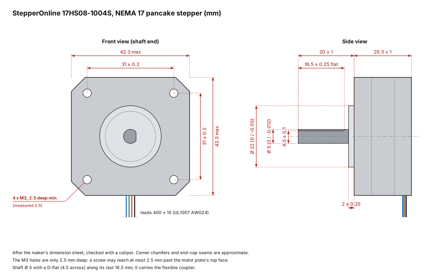
Its four leads, from the sheet, and where they go on the controller PCB's motor header J4 (silkscreen 1A, 1B, 2A, 2B; the TMC2209's M1A, M1B, M2A, M2B). Each coil is a pair: about 3.7 Ω between its two leads, nothing between the pairs, which an ohmmeter confirms before plugging in.
| J4 pin | Silkscreen | Driver output | Lead | Coil |
|---|---|---|---|---|
| 1 (square pad) | 1A | M1A | Black | A |
| 2 | 1B | M1B | Green | A\ |
| 3 | 2A | M2A | Red | B |
| 4 | 2B | M2B | Blue | B\ |
If the motor turns the wrong way, swap the two leads of one coil (black and green, for example). Never plug or unplug the motor with 12 V on: it can destroy the driver.
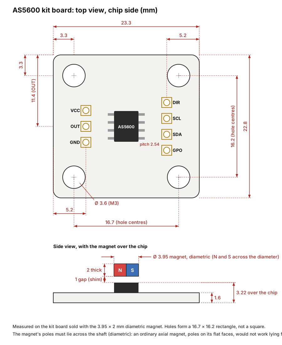
The kit board, measured. Its four mounting holes form a 16.7 × 16.2 mm rectangle (not a square); the diagonal slots in the encoder plate take it as well as the smaller 20 × 20 boards. Mount it chip up, under the magnet, and solder the wires straight into its holes: they run inward under the board, in the 2 mm the standoff pads leave, and down through the diamond window under the chip.
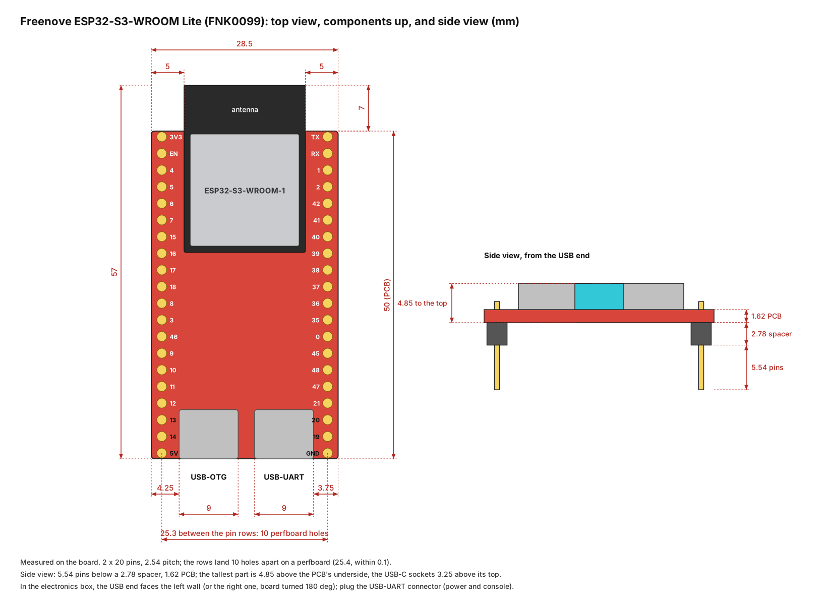
The Freenove ESP32-S3-WROOM Lite, measured. Its two pin rows are 25.3 mm apart, so they land 10 holes apart on the perfboard. It has two USB-C connectors at one end: plug the cable into the USB-UART one (power and console). The module's antenna sticks out 7 mm beyond the other end.
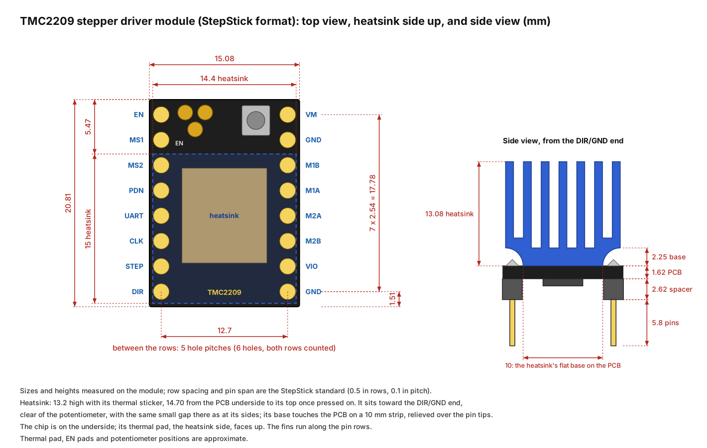
A StepStick-format driver, measured: 20.81 × 15.08 mm, two rows of 8 pins 12.7 mm apart (5 holes on the perfboard). The chip is on the underside; its heatsink (15 × 14.4 mm, fins along the pin rows) sticks onto the thermal pad on top, toward the DIR/GND end so it clears the potentiometer, and stands 14.70 mm from the board's underside.
Check which pin carries the chip's UART. Some modules, such as the TMC2209-LA, have a 0 Ω link that routes it to either the PDN pin (pin 4) or the UART pin (pin 5), and come with it on PDN; the controller uses both. On the PCB, since v1.3, two 0 Ω 0402 jumpers on the back, JP3 (pin 4) and JP4 (pin 5), put the UART line on both pins, so either kind works; leave one out if a module uses that pin for something else. On an older PCB or the perfboard, nothing else uses pin 4, so a short wire between pins 4 and 5 on the board's underside does the same (the firmware README's bring-up, step 5, shows how to tell).
The Sensirion SCD40 on a small 13.70 × 21.70 mm board, measured: 7.85 mm from its underside to the sensor's top, four pin holes 2.54 mm apart along the bottom edge (GND, VDD, SCL, SDA). It carries its own I²C pull-ups (R1, R2, 10 kΩ), so the controller needs none for it. On the controller PCB, J5 has the same pin order, so a straight 4-wire cable joins them. Keep the sensor's membrane uncovered (see the warning below).
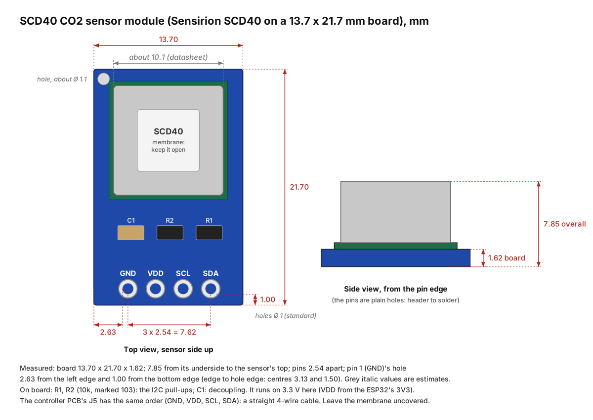
[!WARNING] SCD40: do not remove the white membrane on top of the sensor. It looks like a small sticker, but it is part of the sensor: a gas-permeable filter that lets ambient air reach the photoacoustic NDIR cell while keeping dust, splashes and other contaminants out. Do not press on it, cover it, or clean near it with solvents or compressed air.
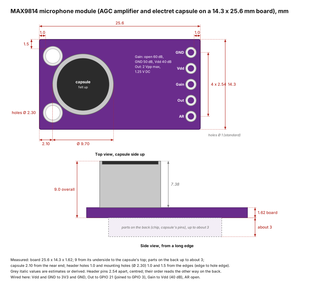
For the audio mode, measured: 25.6 × 14.3 × 1.62 mm, 9 mm from its underside to the capsule's top, and parts up to about 3 mm on the back. The 9.70 mm capsule sits 2.10 mm from one end, centred across the board; the five header holes (GND, Vdd, Gain, Out, AR) run along the other end, and two mounting holes flank the capsule. Tie Gain to Vdd (40 dB) and leave AR open. It lies capsule down in the microphone tube.
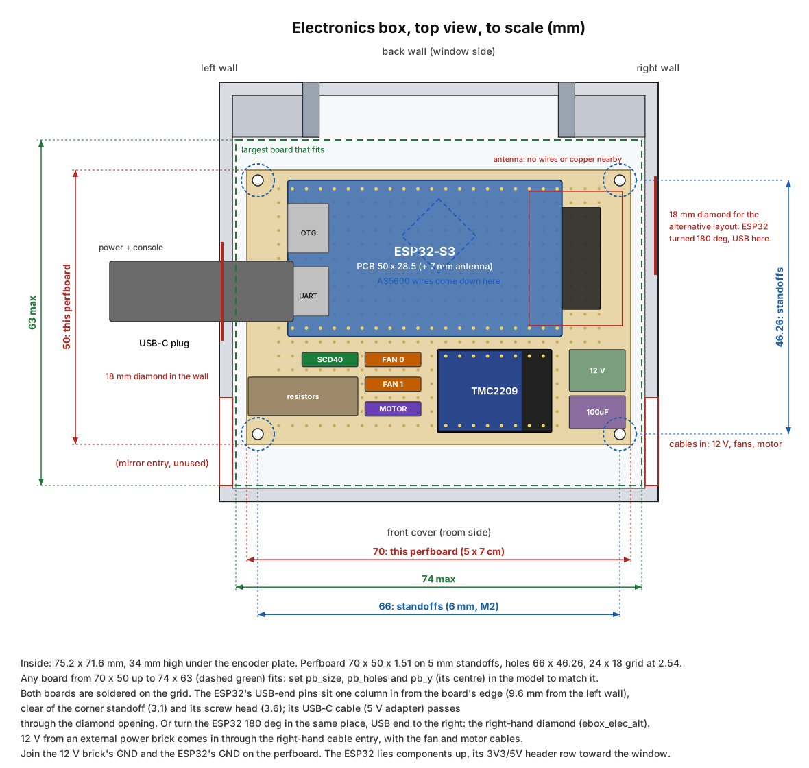
The box seen from above, to scale, with the room at the bottom. The ESP32 lies across the back half, its pins soldered on the perfboard's grid, with its USB-end pins one column in from the board's edge so they clear the corner standoff; the TMC2209 sits at the front right, next to the 12 V terminal and the cable entry. The ESP32 can also be turned 180° in the same place, USB end toward the right wall: the box has a diamond opening on each side (views ebox_elec and ebox_elec_alt in the model). Keep wires and copper away from the antenna's end.
The ESP32 runs Arduino sketches (esp32 core 3.x). The first, firmware/baremetal/, is a serial command console that tests each electronic part on its own: fans, motor and driver, encoder, CO₂ sensor, temperature probes and the 12 V supply, and optionally a microphone's sound level (audio mode). The second, firmware/webui/, is the application: the CO₂ control, with its own web page on the home network for the live readings, graphs, settings and manual control, and a simulation that stands in for the sensors until they're connected. Both compile cleanly, and the web application runs on the bare ESP32 board in simulation, and the bare-metal console has now checked every part on the bench. firmware/README.md has the board settings, the wiring diagram, a part-by-part bring-up, the command list and the web application.

Building the perfboard. The build plan puts this wiring on the 5 × 7 cm protoboard: the ESP32-S3 and the TMC2209 on their grid positions in the box, the headers, resistors, capacitor and 12 V terminal around them, and 61 numbered wires on the underside, each listed with both of its holes. A PDF version splits it over three landscape Letter pages for the bench: the component side, the solder side and the wire list. Solder the parts and the wires that run under the modules first, then the two modules.

Or a printed circuit board. The same circuit also exists as a 2-layer PCB of the protoboard's size (70 × 50 mm, 1.6 mm) with the same four M2 holes, so it drops into the box in its place: the ESP32-S3 and the TMC2209 sit on exactly the same pins, and every connector keeps its function. It adds a ground plane on both layers, 0.8 mm tracks for 12 V and the motor, a 1N5822 against a reversed 12 V plug (a jumper on JP1 bypasses it), test pads for GND, 3V3, VIN, 12 V and the TMC2209's DIAG, and since v1.1 a jumper on the back, JP2, that joins GPIO 21 to GPIO 3 for the firmware's audio mode (on v1.0, a short wire does it). Since v1.2, the 1-Wire pull-ups R9 and R10 lie flat on the back: on v1.1 they stood in the path of the ESP32's second USB-C plug (the unused USB-OTG one). Since v1.3, the jumpers are 0402 pads for a 0 Ω resistor or a short wire (JP2 was a solder jumper), and JP3 and JP4 put the TMC2209's UART line on both pins 4 and 5. Since v1.4, J7 is a 2 × 3 header for an INMP441 I²S microphone: its first row is the old 3-pin header (3V3, IN, GND) for the indoor DS18B20 or the MAX9814, and the second row adds WS (GPIO 39), SCK (GPIO 38) and a GND for the microphone's L/R pin, with SD on IN (GPIO 21). To make room, the motor header J4 stands beside the TMC2209, the SCD40's J5 takes J4's place on the bottom row, and R3 and R4 sit under J7. Five boards cost US$10 to 32 at PCBWay with shipping, depending on its speed: upload the Gerber zip and keep the standard options (2 layers, FR-4, 1.6 mm, 1 oz, HASL lead-free). The schematic and the KiCad 10 project are in pcb/; the scripts tools/pcb_*.py build all of it, Freerouting doing the routing.
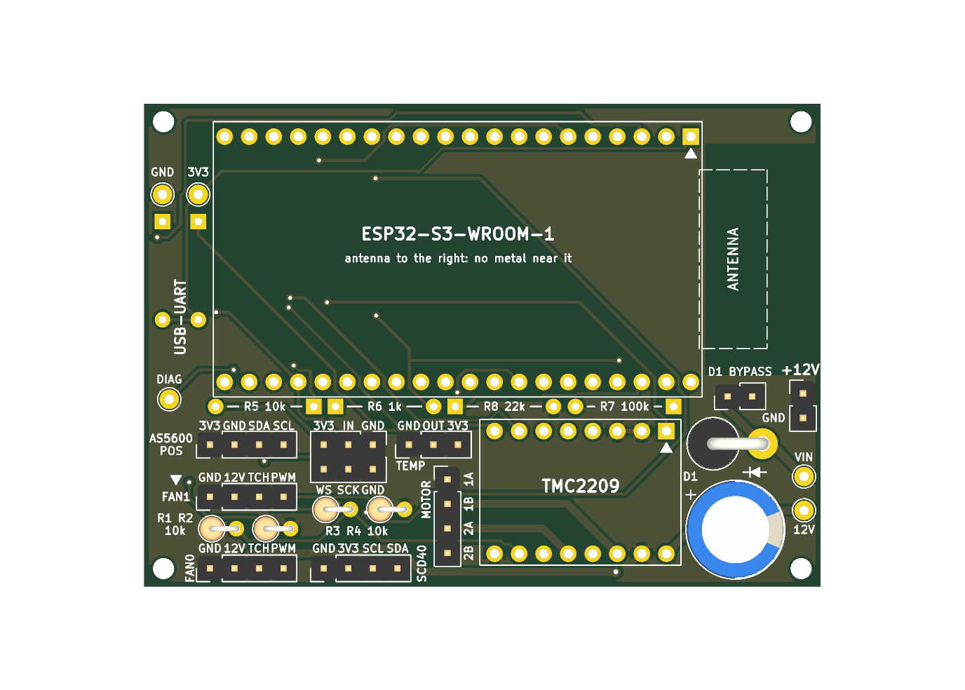
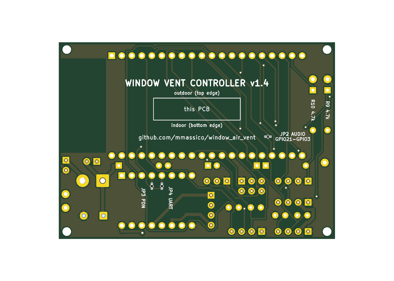
| Ref | Qty | Value | Part / note |
|---|---|---|---|
| U1 | 1 | Freenove ESP32-S3 Lite (FNK0099) | see Hardware |
| U2 | 1 | TMC2209 module | see Hardware |
| D1 | 1 | 1N5822 | Schottky, 3 A 40 V, DO-201AD, standing |
| C1 | 1 | 220 µF 50 V | electrolytic, 10 mm, 5 mm pitch |
| R1–R4 | 4 | 10 kΩ | 1/4 W, standing |
| R5–R8 | 4 | 10 kΩ, 1 kΩ, 100 kΩ, 22 kΩ | 1/4 W, lying flat, component side: body 2.5 mm (max), otherwise: solder side |
| R9, R10 | 2 | 4.7 kΩ | 1/4 W, lying flat on the solder side (v1.2; standing on v1.1); leave R9 out in audio mode (or without the indoor probe) |
| J1, JP1 | 2 | 2-pin header | plus a jumper shunt for JP1 |
| J2–J6 | 5 | 4-pin header | 2.54 mm male |
| J7 | 1 | 2 × 3 header | 2.54 mm male (v1.4; a 3-pin header before) |
| J8 | 1 | 3-pin header | 2.54 mm male |
| JP2 | 0 Ω 0402 | on the back; fitted (or a wire) in audio mode only | |
| JP3, JP4 | 2 | 0 Ω 0402 | on the back, under the TMC2209's pins 4 and 5; or a short wire each |
The AS5600 measures the direction of the magnetic field across the shaft, so the magnet's north-south axis must lie across the shaft and turn with it.
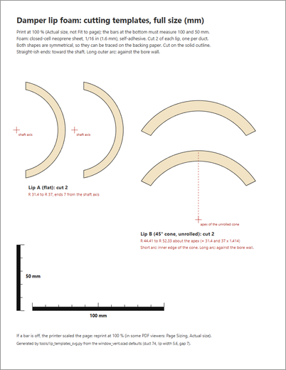
magnet = "diametric", magnet_d = 4, magnet_h = 2); set them to the one you have.magnet = "sideways" for a cap that holds a 2 × 2 mm cylinder across the shaft. A magnet that small may be too weak at 1–2 mm; the AS5600's status register reports "too weak / OK / too strong", so check it once.Full-size templates for the foam on the four lips (two per duct). The flat lip takes a half-ring; the conical lip takes the cone unrolled, a flatter arc that lies on the 45° slope without wrinkles. Print the PDF at 100 % (Actual size, not Fit to page), check its 100 mm and 50 mm bars with a ruler, then trace the shapes on the foam's backing paper and cut.
Cutting guides (optional). Rigid printed copies of the two templates, foam_guide_a and foam_guide_b. The plate is the strip's exact outline: press it on the foam by its finger grip, which holds the sheet still, and run a craft knife along its edges, blade upright against the plate. The grip and the rib under it stay inside the edges, clear of the blade, and the rib stops short of the ends, so the knife can cut across them. Cut with the backing paper up (it slips less than the bare foam), in two or three light passes. Tested: much easier, faster and more accurate than cutting around the paper templates. Leave the slicer's elephant-foot compensation on: the blade runs against the plate's bottom edge.
| Part | Thumbnail | Size (mm) | Time | Print orientation |
|---|---|---|---|---|
foam_guide_a | 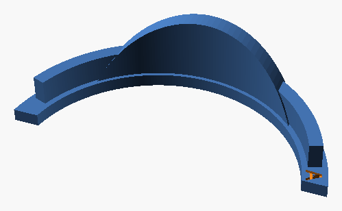 | 73 × 30 × 18 | about 15–20 min | Plate on the bed, grip up |
foam_guide_b | 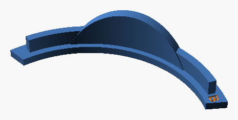 | 87 × 27 × 18 | about 15–20 min | Plate on the bed, grip up |
Cutting the foam neatly takes some care: a sharp blade and a steady hand, and a second try is not unusual. Tweezers help to lay the narrow strips on the lips inside the ducts. If that sounds like too much, see without lip foam below.
How the gap is set. The housing places the lips for a 1 mm gap (gasket = 1), but 1.6 mm neoprene squeezed that much is too stiff: even a finger can't close the disc on it, and light shows through. So the discs make the room instead, and the housing never changes. seat_rlf moves each of the disc's two seats: [0] lowers half A's face (or raises it, when negative), [1] sets half B's bevel back square to the slope (or forward). The gap at each seat is gasket + seat_rlf, less 0.1 mm on A and plus about 0.07 mm on B: the grub screws push the shaft into one side of its bore, which moves the disc 0.1 mm toward lip A. With foam, seat_rlf = [0.6, 0.5] gives gaps of about 1.5 mm on both seats, so the foam is only lightly squeezed (half A's face lands at 2.4 mm, a whole number of 0.2 mm layers).
disc_nofoam closes on the bare lips instead, so there is nothing to cut or stick: print it instead of disc and skip the foam. In the model, lip_foam = false does the same (seat_rlf = [-0.6, -0.8]): half A is thickened to 3.6 mm and half B's bevel shrinks, leaving gaps of about 0.3 mm on both seats. The housing is the same either way, so you can switch later by printing the other discs.
The trade-offs:
To adjust (open cad/window_vent.scad in OpenSCAD, change seat_bare, export part = "disc_nofoam"):
[-0.4, -0.6] gives about 0.5 mm). Change them in steps of 0.2 mm on half A, so its face stays on a 0.2 mm layer.-0.9), but below about 0.2 mm the disc risks binding on a slightly warped print. Print one disc and try it before printing the second.python tools/check.py vent runs the swing, stop and fitting checks for both discs.The insert takes two 83 mm holes, 96 mm apart, intake on top. The housing's plain Ø 83.7 spigots are a snug fit in them (the saw measures 83.3 across its teeth, so its holes come out about 83.3), so no O-rings are needed (sand a tight hole a little). Print the drilling template at 100 %, check its 100 mm bars, tape it on the foam centred across its width, and mark both centres with an awl. The template also marks an optional hole for the outdoor temperature probe, above the intake.
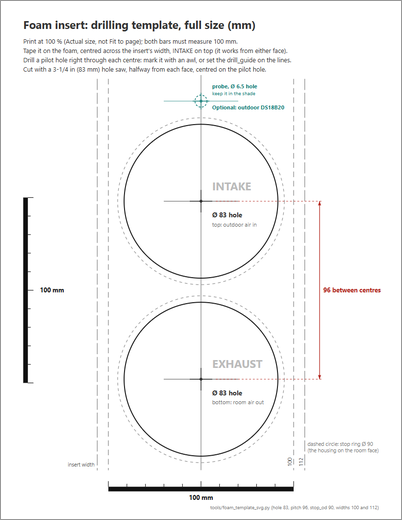
Straight pilot holes (optional). A pilot hole that leans sends the hole saw off its line on the far face. The printed drill_guide keeps the bit perpendicular: two 20 mm bushings, A for the hole saw's pilot holes (5.2 mm bit, or 13/64 in: slightly smaller than the saw's 5.8 mm pilot drill, which then follows the hole) and B for the probe's hole (6 mm, or 15/64 in: snug on the 6 mm probe), set in guide_d to suit your bits. Lay it on the taped template: the notches at both ends on the vertical centre line, and the side notches of the bushing you use on that hole's cross line. Hold it down and drill straight through the paper and the foam; then move it to the next hole. The bit has to reach through 20 mm of bushing and 51 mm of foam, so use one with at least 75 mm of flute (a 6 in aircraft bit, for instance). Run each bit through its bushing once before the first hole, to size the bore.
| Part | Thumbnail | Size (mm) | Time | Print orientation |
|---|---|---|---|---|
drill_guide | 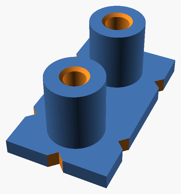 | 26 × 46 × 20 | about 20 min | Base on the bed, bushings up |
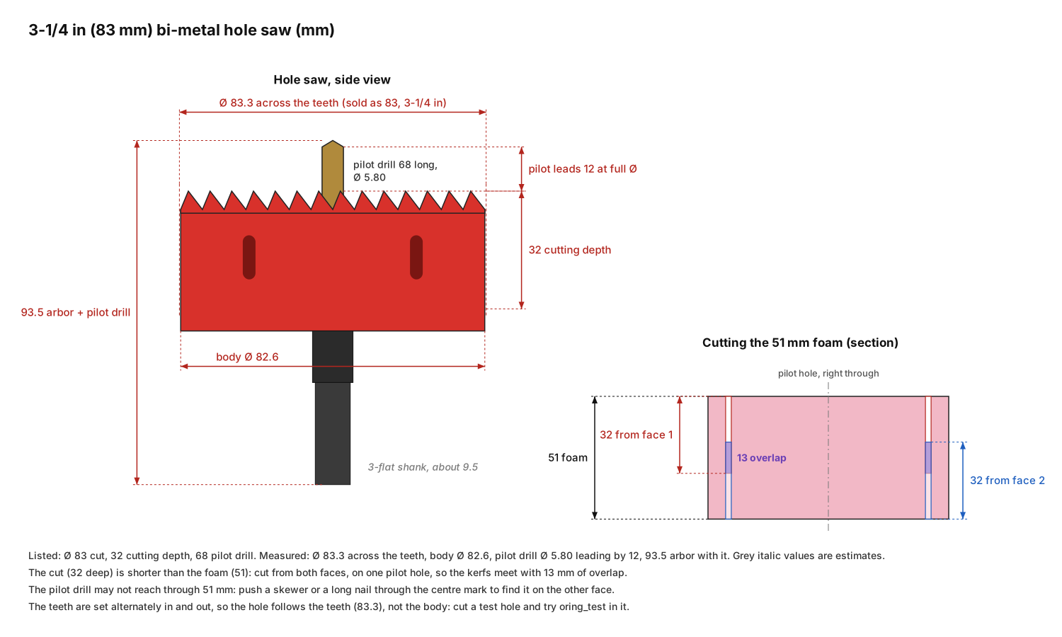
A 3-1/4 in (83 mm) bi-metal hole saw cuts only 32 mm deep, less than the 51 mm foam. Two ways to get through:
Run the drill slowly. Hole saws often cut a little wider than labelled, so cut a test hole in a scrap first and try oring_test in it. A hot-wire foam cutter also works, and leaves the smoothest bore.
A printed frame holds a fibreglass insect screen on the foam's outdoor face, over both holes. The mesh is pressed into a groove around the frame's edge by screen spline, the way a window screen is made, so it comes out for cleaning or replacement: pollen and fluff build up on the intake side, and every clog costs airflow. Two short sleeves on the frame's back plug into the holes' outdoor ends (the housing's spigots fill only the room-side 25 mm of the foam): they centre the frame, hold it, and keep insects from getting in behind it. Four countersunk screws in the corners keep it in place. At 94 mm wide, it fits between the caps' lips, flush with them. Its top edge is 95 mm above the vent's centre, clear of the probe's hole at 102 mm.
Each sleeve has a 15 mm drain slot at the bottom, through its wall and the plate. Condensation runs along the hole's floor, so without the slot it would pool against the sleeve's end and soak into the foam. The slot's floor is flush with the hole's floor and drops 1 mm toward the outdoor face, so the water runs out under the mesh. The exhaust hole, the lower one, carries warm, damp room air out into the cold, so it gets the most.
| Part | Thumbnail | Size (mm) | Print orientation |
|---|---|---|---|
screen_frame | | 94 × 193 × 15 | Outdoor face on the bed, sleeves up |
screen_test | 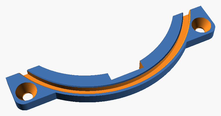 | 94 × 27 × 15 | Outdoor face on the bed |
Try the groove first. screen_test is the frame's bottom end: an arc of the groove, two screw holes and an arc of sleeve with its drain. The 2.8 mm groove has been tested with 0.125 in screen spline over fibreglass mesh, and it works well. The O-ring cord hasn't been tried yet, and other splines vary, so roll yours over a scrap of mesh into the test piece first: it should go in with a firm push of the roller and not pop out when the mesh is pulled. If it is loose or too hard to roll in, change the groove's width, scr_groove[0] (2.8 mm), in cad/window_vent.scad. Try the screws in a foam scrap at the same time.
Fitting the mesh.
Fitting the frame. Push the sleeves into the holes from outdoors, then put the four screws through the corners into the foam. Screws about 25 mm long reach 20 mm into the foam, which is plenty, since the sleeves carry the frame.
An optional tray on the window ledge, under the whole unit, from 6 mm off the foam (clear of the bottom cap's lip) to just past the fans. It catches drips of condensation, which evaporate indoors, and it levels the unit on a ledge that isn't flat. The electronics box, the unit's lowest part, stands on seven 3 mm ribs, so it stays above any water. The ribs are evenly spaced across the tray, 13.1 mm apart, and stiffen its thin floor under the unit's weight, the outer two under the box's side walls. Each stops 2 mm short of the walls at its ends, so water can pass from one channel to the next; the outer two pass close to the corner posts, so they stop 2 mm short of the posts instead. At 112 mm wide, the tray reaches 15.9 mm past the fans on each side, so it needs about 16 mm or more beside the fans: a window frame's wall 20 mm away leaves about 4 mm.
A leg in each corner sets the height. Each one is an M3 × 20 button head screw and a square foot with a captive nut, which slides in the corner post's socket. The screw goes in from below, and its head presses up into a 45° pyramid that closes the top of the socket. Turning the screw from above, with a 2 mm hex key through the hole in the post's top, moves the foot up or down: 0.5 mm per turn. An M2 × 6 flat head screw, through the post's outer wall (3.5 mm thick, for its thread), rides in a groove up the foot. It holds the leg in when the tray is lifted, and the groove's ends stop the foot, so the floor's underside sits 4 to 11 mm above the ledge. The posts stand beside the electronics box, inside the tray's outline.
Print without supports. Nothing in the posts or the feet needs one: the pyramid's faces slope at 45°, and the feet print on their side with the nut's slot and the groove facing up. Supports inside a post can't be removed (tried), and the first design's flat ceilings, bridged without supports, sagged too much for the screw's head.
| Part | Thumbnail | Size (mm) | Print orientation |
|---|---|---|---|
tray | | 112 × 115 × 22 | Floor on the bed |
tray_feet | | 9 × 9 × 20 each, four | On its side, the nut's slot and the groove up |
tray_test | 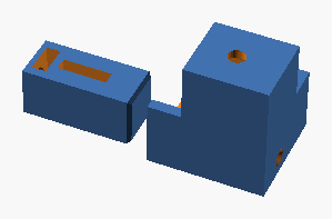 | 44 × 19 × 22 | Floor on the bed, the foot on its side |
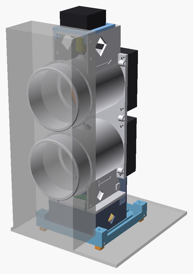
Try a leg first. tray_test is one corner of the tray, with its post, and a foot. Fit a screw, a nut and the M2 stop as below and check that the foot slides freely without wobbling, that the screw turns easily under a little load, and that the stop holds the foot at both ends of its travel. Then fill the whole tray with water once, before trusting it.
Fitting the legs.
Levelling. Set the tray on the ledge with the feet at about 7 mm. Level it across and along with three legs, then bring the fourth down until it just starts to resist the key: four legs on a ledge that isn't flat, and no rocking. A slight tilt toward the foam (about 1 mm lower there) also helps the ducts drain outward.
The foam holes come after the tray. The tray sets the unit's height, so drill the holes to match it: stand the unit on the levelled tray against the foam, mark the hole centres from it, then drill. Keep the unit below the window's latch zone.
disc_nofoam, skip this step.ebox_elec_alt): the box has a diamond on each side. Wire it (connect the 12 V brick's GND to the ESP32's GND), and screw it onto the four standoffs in the box (M2). Plug the USB-C cable in through the matching side wall. Bring the 12 V wire and the fan and motor cables down the right side, tie them to the three anchors behind the fans, and into the box through the notch at the top of its right wall. The AS5600 wires drop in through the window in the encoder plate.tube_spacer over both spigots, up against the stop rings. Then push the spigots into the foam holes: the spacer ends up squeezed between the stop rings and the foam. If they're tight, sand the holes a little. (With orings = true, roll two O-rings onto each spigot first.)In winter the incoming air is cold, and a jet straight off the fan can feel like a draft. These louvers clip onto the room face of the intake fan and aim the air: upward along the ceiling, for example, so it mixes with the room air before it reaches anyone.
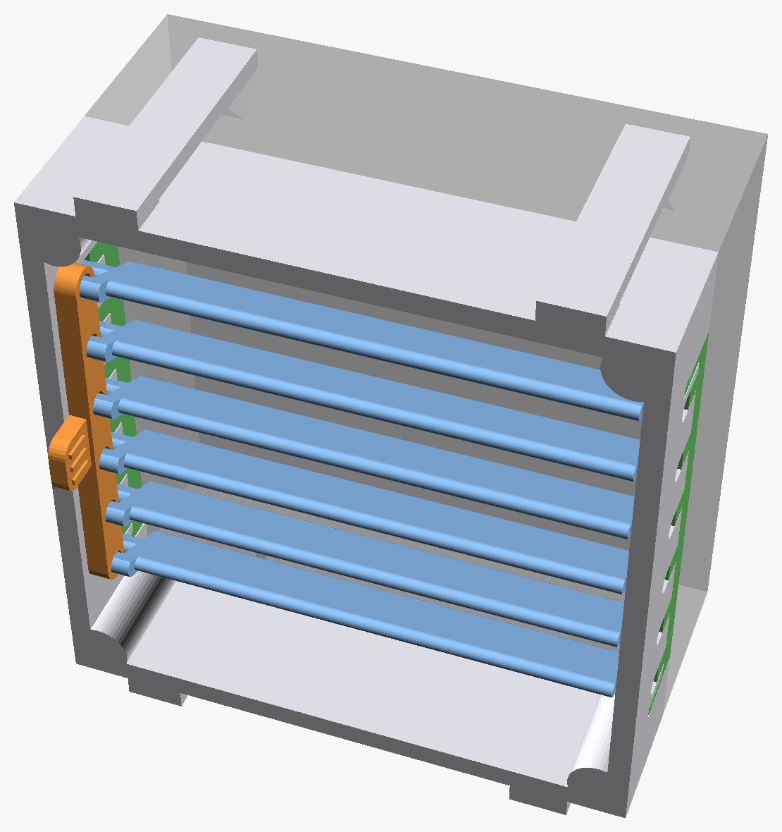
link_side = "back" to hide the link between the blades and the fan instead, without the tab.)louver_link has a thinner bar for a strip of felt or foam tape that rubs on the wall.)| Part | Thumbnail | Qty | Description | Size (mm) | Print orientation |
|---|---|---|---|---|---|
louver_chassis | 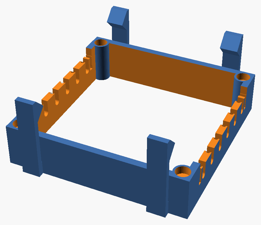 | 1 | Frame: clips onto the fan's corner flanges (recesses clear its screw heads), U-slots for the blade pins in both side walls | 80 × 86 × 36 | Front face on the bed, clips up |
louver_blade | 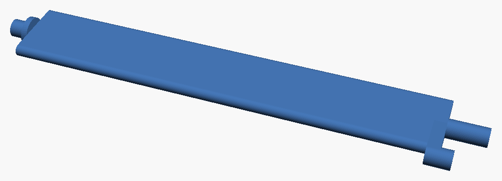 | 6 | Blade with a pivot pin at each end, a collar on one side and an offset pin for the link on the other | 79 × 14 × 3.5 | Flat; its pins are flattened on the bed side |
louver_link_nopad | 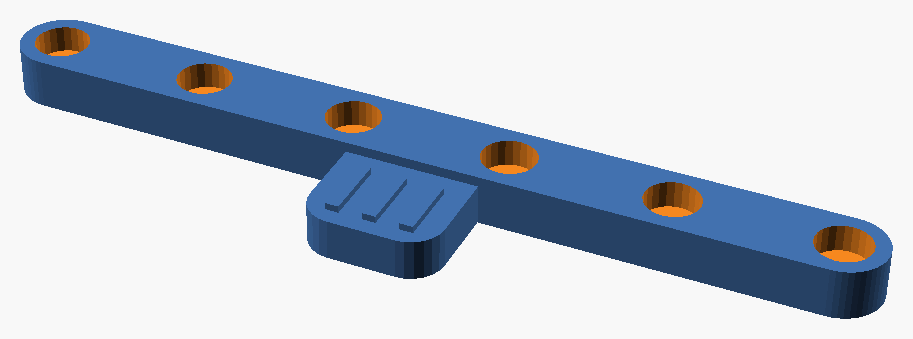 | 1 | Link bar joining the six offset pins, so the blades turn together, with the tab that sets the angle; its bar is 3 mm thick (the tab 2.4) | 53 × 11 × 3 | Flat, holes and ribs up |
louver_link | 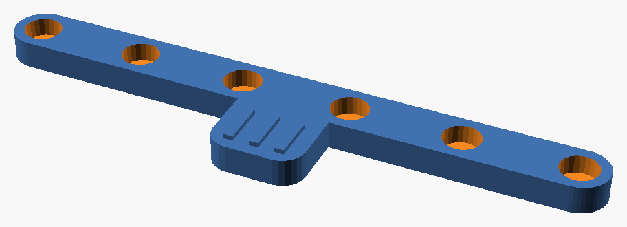 | (1) | Optional, instead of louver_link_nopad: the same link with a thinner bar (2.4 mm) for a felt strip on its flat face | 53 × 11 × 2.8 | Flat, holes and ribs up |
louver_retainer |  | 2 | Retaining comb, one per side wall: plugs the slots behind the pins, with a snap arm at each end | 3 × 57 × 11 | Spine down, pegs up |
About 33 cm³ (42 g) of PETG in all. With the optional louver_link, also a strip of 1 mm felt or foam tape, about 5 × 52 mm.
Assembly:
louver_link: stick the felt strip on the link bar's flat face (the face without holes).Tuning after a test print, in cad/louvers.scad:
slot_w: the grip of the pins in their slots. Lower makes the blades stiffer.clip_lip, clip_edge and clip_w: the clips. They're sized for the Noctua NF-A8 (a 7 mm corner flange, with the clips 8 mm in from the side edges so they clear the corner screws).pad_t and pad_sq: the friction strip and how much it's squeezed.comb_fit, comb_key, key_shape, key_clr and snap_l, snap_t, snap_b: the combs' pegs in their slots, the guide ridge under each peg in its groove (half-round by default, or a V), and the snap arms. Print peg_test2 first (about 25 min): a three-slot slice of the side wall, cut from the chassis itself, with a three-peg comb and its snap arms.doc/ reference drawings: the motor, the AS5600, ESP32-S3, TMC2209 and SCD40
boards, the electronics box layout, the perfboard build plan (and PDF);
the lip foam and foam insert templates (PDF, to print at 100 %), the
hole saw
images/ renders used in this README
cad/window_vent.scad parametric model (Customizer; part = "assembly" for the preview)
cad/louvers.scad optional adjustable louvers for the intake fan
stl/ exported parts (default parameters)
pcb/ the controller PCB (KiCad 10): schematic and its PDF, board, Gerber zip
for ordering, renders
tools/check.py geometry checks (must print ALL CHECKS PASSED); vent or louvers: just one
tools/wiring_svg.py draws firmware/images/wiring.svg (the wiring diagram)
tools/as5600_svg.py draws doc/as5600.svg (the AS5600 board, dimensioned)
tools/ebox_layout_svg.py draws doc/ebox_layout.svg (the electronics box, to scale)
tools/esp32_svg.py draws doc/esp32_s3.svg (the ESP32-S3 board, dimensioned)
tools/tmc2209_svg.py draws doc/tmc2209.svg (the TMC2209 module, dimensioned)
tools/scd40_svg.py draws doc/scd40.svg (the SCD40 CO2 sensor board, dimensioned)
tools/max9814_svg.py draws doc/max9814.svg (the MAX9814 microphone board, dimensioned)
tools/motor_svg.py draws doc/motor_17hs08.svg (the stepper motor, dimensioned)
tools/motor_mount_svg.py draws doc/motor_mount.svg (section through a motor screw)
tools/lip_templates_svg.py draws doc/lip_templates.svg and .pdf (full-size foam templates) and
their preview
tools/foam_template_svg.py draws doc/foam_template.svg and .pdf (drilling template for the foam
insert) and its previewCopyright (c) 2026 Marc-Antoine Massicotte.
This design (CAD model, STL files, images, documentation and scripts) is released under the CERN Open Hardware Licence Version 2 - Permissive (CERN-OHL-P-2.0). You may use, modify, make, share and sell it freely, as long as you keep this notice. It comes with no warranty of any kind, and the author accepts no liability for its use.
The firmware in firmware/ is software, so it is released under the MIT License instead: same idea, free to use, modify and share, keep the notice, no warranty.
| Qty | Value | Footprint | References |
|---|---|---|---|
| 4 | 10k | Resistor_THT:R_Axial_DIN0207_L6.3mm_D2.5mm_P2.54mm_Vertical | R1, R2, R3, R4 |
| 4 | M2 | MountingHole:MountingHole_2.2mm_M2 | H1, H2, H3, H4 |
| 2 | 4.7k | window_vent:R_DIN0207_P10.16mm_Flat_Tight | R9, R10 |
| 1 | 0R AUDIO | Resistor_SMD:R_0402_1005Metric_Pad0.72x0.64mm_HandSolder | JP2 |
| 1 | 0R PDN | Resistor_SMD:R_0402_1005Metric_Pad0.72x0.64mm_HandSolder | JP3 |
| 1 | 0R UART | Resistor_SMD:R_0402_1005Metric_Pad0.72x0.64mm_HandSolder | JP4 |
| 1 | 100k | window_vent:R_DIN0207_P10.16mm_Flat_Tight | R7 |
| 1 | 10k | window_vent:R_DIN0207_P10.16mm_Flat_Tight | R5 |
| 1 | 12V | TestPoint:TestPoint_THTPad_D2.0mm_Drill1.0mm | TP4 |
| 1 | 12V IN | Connector_PinHeader_2.54mm:PinHeader_1x02_P2.54mm_Vertical | J1 |
| 1 | 1N5822 | Diode_THT:D_DO-201AD_P5.08mm_Vertical_AnodeUp | D1 |
| 1 | 1k | window_vent:R_DIN0207_P10.16mm_Flat_Tight | R6 |
| 1 | 220uF 50V | Capacitor_THT:CP_Radial_D10.0mm_P5.00mm | C1 |
| 1 | 22k | window_vent:R_DIN0207_P10.16mm_Flat_Tight | R8 |
| 1 | 3V3 | TestPoint:TestPoint_THTPad_D2.0mm_Drill1.0mm | TP2 |
| 1 | AS5600 | Connector_PinHeader_2.54mm:PinHeader_1x04_P2.54mm_Vertical | J6 |
| 1 | D1 bypass | Connector_PinHeader_2.54mm:PinHeader_1x02_P2.54mm_Vertical | JP1 |
| 1 | DIAG | TestPoint:TestPoint_THTPad_D2.0mm_Drill1.0mm | TP5 |
| 1 | DS18B20 in / MIC | Connector_PinHeader_2.54mm:PinHeader_2x03_P2.54mm_Vertical | J7 |
| 1 | DS18B20 out | Connector_PinHeader_2.54mm:PinHeader_1x03_P2.54mm_Vertical | J8 |
| 1 | FAN 0 intake | Connector_PinHeader_2.54mm:PinHeader_1x04_P2.54mm_Vertical | J2 |
| 1 | FAN 1 exhaust | Connector_PinHeader_2.54mm:PinHeader_1x04_P2.54mm_Vertical | J3 |
| 1 | Freenove ESP32-S3 Lite | window_vent:Freenove_ESP32S3_Lite | U1 |
| 1 | GND | TestPoint:TestPoint_THTPad_D2.0mm_Drill1.0mm | TP1 |
| 1 | MOTOR | Connector_PinHeader_2.54mm:PinHeader_1x04_P2.54mm_Vertical | J4 |
| 1 | SCD40 | Connector_PinHeader_2.54mm:PinHeader_1x04_P2.54mm_Vertical | J5 |
| 1 | TMC2209 module | window_vent:TMC2209_StepStick | U2 |
| 1 | VIN | TestPoint:TestPoint_THTPad_D2.0mm_Drill1.0mm | TP3 |
hackclub/OnBoard
💡 Join 1,000 teenagers and make your first PCB with a $100 grant!


ozel/DIY_particle_detector
A mobile low-cost spectrometer for measuring radioactivity and the energy of ionising radiation like alpha particles and electrons

Seeed-Studio/OSHW-reCamera-Series
reCamera is a series of open-source AI cameras.


It measures 70 × 50 mm and has 2 copper layers, 1.6 mm thick.
35 parts. The full list of its parts is on this page, with links to each part's symbol and footprint where PCBKit's library has them.
From the mmassico/window_air_vent repository on GitHub, at the commit this page was made from: the board is pcb/window_vent_ctrl.kicad_pcb and its schematic pcb/window_vent_ctrl.kicad_sch. PCBKit opens the board in the browser, with nothing to install.
Its repository publishes it under the CERN-OHL-P-2.0 licence: you may reuse it on that licence's terms (keep the author's notice, and for a copyleft licence share your changes alike).