2 layers27.9 × 16.5 mm

 mmalecki/lc-0
A simple, switch-based launch controller for model rockets
Lc-0 is an open-source printed circuit board by mmalecki, from the mmalecki/lc-0 repository on GitHub. It is a 2-layer board of 63.8 × 30.5 mm with 18 parts on 8 nets, routed with 28 tracks and 0 vias.
Its parts include 2 capacitors, 1 diode and 1 fuse.
Simple switch-based model rocket launcher. When I say simple, I mean it!
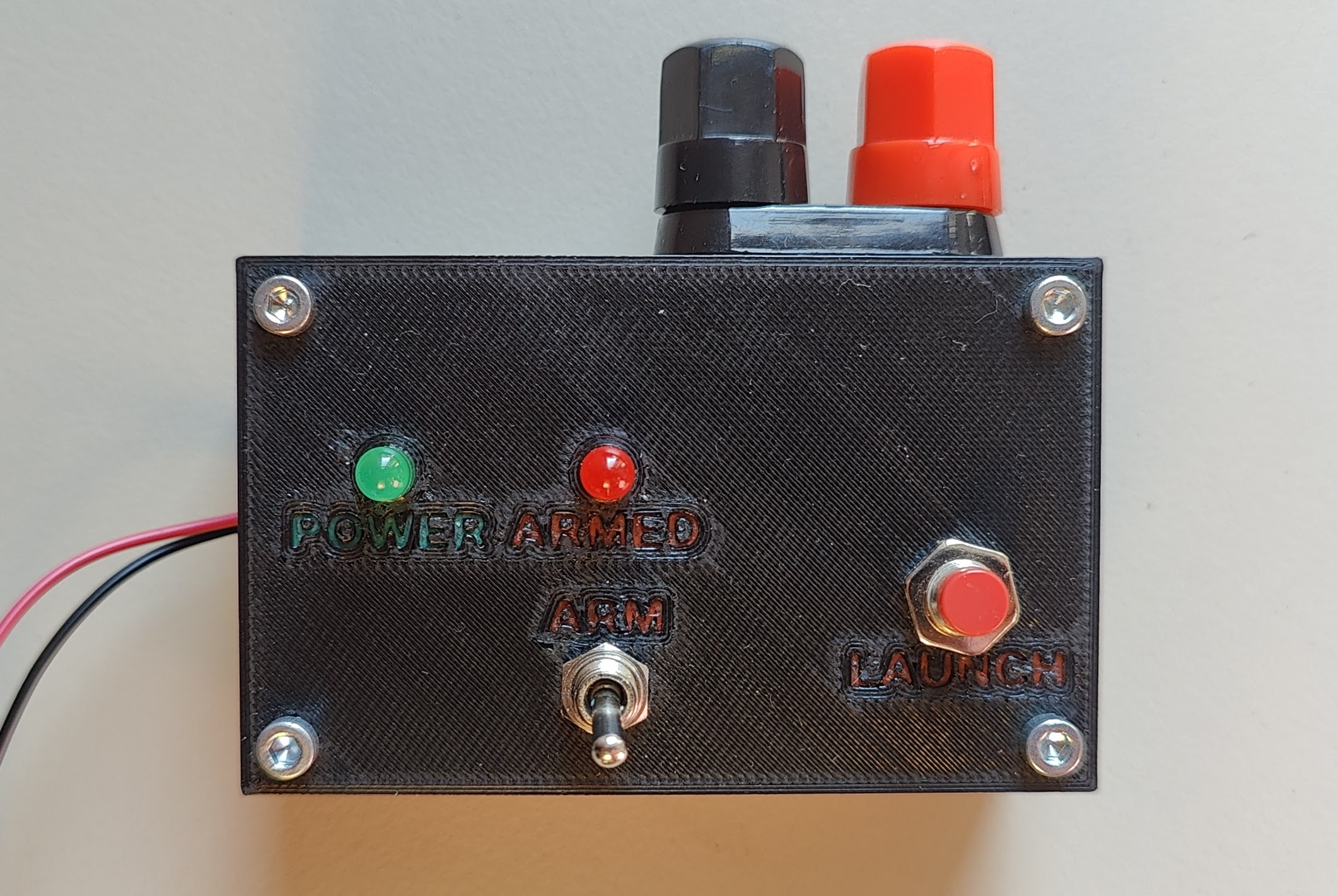
Continuity checking? Yeah, sure, I'll tell you I've heard about it.
Keyed arm switch? Right, as if I had any keys laying around doing NOTHING.
I mean, frankly, the thing doesn't even have space for batteries in its enclosure.
On the other hand, its most complicated components is probably the LED telling you the launcher is receiving power. (What, were you hoping for a switch?)
You can load a larger capacitor in there to fire a cluster of rockets with a 9 V battery, and the 2 mm traces should withstand about anything.
First, clone this repository:
git clone https://github.com/mmalecki/lc-0
cd lc-0
git submodule update --initelectronics directory. Get the PCB made (one-sided
is all that's needed here).enclosure.| Qty | Value | Footprint | References |
|---|---|---|---|
| 4 | Conn_01x01 | Connector_Wire:SolderWire-1.5sqmm_1x01_D1.7mm_OD3.9mm | IGNITER-1, IGNITER+1, J+9.6V1, JGND1 |
| 4 | MountingHole_3.2mm_M3_DIN965_Pad | MountingHole:MountingHole_3.2mm_M3_DIN965_Pad | M3, M3, M3, M3 |
| 2 | 360 | Resistor_THT:R_Axial_DIN0207_L6.3mm_D2.5mm_P10.16mm_Horizontal | RLEDARMED1, RLEDPOWER1 |
| 2 | 470 uF | Capacitor_THT:CP_Radial_D10.0mm_P5.00mm | C1, C2 |
| 2 | LED | Connector_PinHeader_2.54mm:PinHeader_1x02_P2.54mm_Vertical | ARMED1, POWER1 |
| 1 | D_Schottky | Diode_THT:D_DO-201AD_P15.24mm_Horizontal | D1 |
| 1 | Fuse | Fuse:Fuseholder_Cylinder-5x20mm_Bulgin_FX0457_Horizontal_Closed | F1 |
| 1 | SW_Push | Connector_PinHeader_2.54mm:PinHeader_1x02_P2.54mm_Vertical | LAUNCH1 |
| 1 | SW_SPST | Connector_PinHeader_2.54mm:PinHeader_1x02_P2.54mm_Vertical | ARM1 |
It measures 63.8 × 30.5 mm and has 2 copper layers, 1.6 mm thick.
18 parts. The full list of its parts is on this page, with links to each part's symbol and footprint where PCBKit's library has them.
From the mmalecki/lc-0 repository on GitHub, at the commit this page was made from: the board is electronics/lc-0.kicad_pcb and its schematic electronics/lc-0.kicad_sch. PCBKit opens the board in the browser, with nothing to install.
Its repository states no licence, so its author keeps all rights: ask mmalecki before reusing the design.

VoronDesign/Voron-Hardware
Cool Hardware designed by the Voron Design group


hackclub/OnBoard
💡 Join 1,000 teenagers and make your first PCB with a $100 grant!

VoronDesign/Voron-Tap
Tap is a nozzle-based z-probe for the V2 and Trident printer designs. The entire toolhead moves to trigger an optical switch. Tap offers many advantages:

Luos-io/luos_engine
Open-source and real-time orchestrator for cyber-physical-systems, to easily design, test and deploy embedded applications and digital twins.


Twotoz/C5VRX
Ultra-minimal, zero-CPU 5.8 GHz analog FPV video receiver using ESP32-C5 Wi-Fi 6 PHY MODEM_DIAG, BitScrambler WBFM demodulation & resistor DAC CVBS