
2 layers136.2 × 85.9 mm
BATDATUNIT01
mlab-modules/BATDATUNIT01
Multiple parallel Li-ion 18650 battery cell module with BMS and data storage with MCU control.
225 parts5GPL-3.0
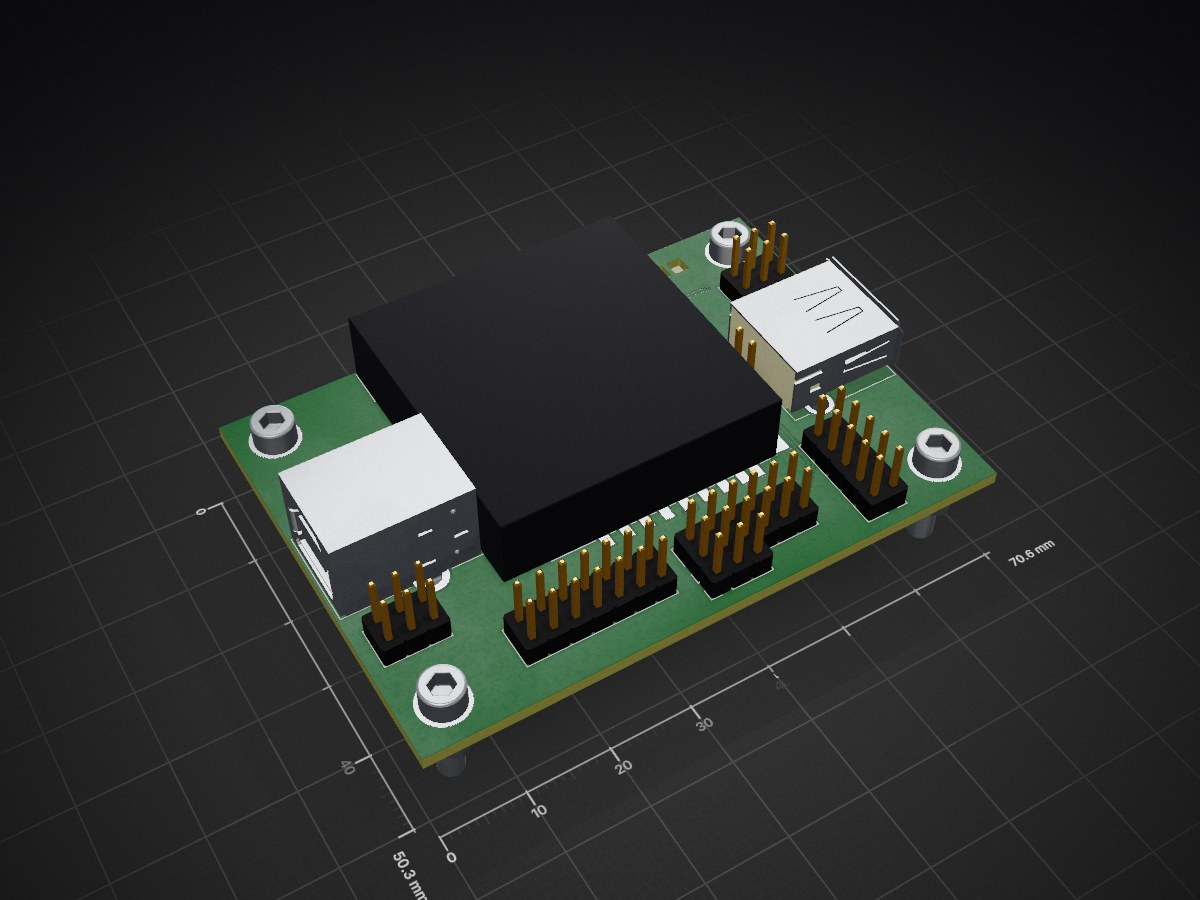
 mlab-modules/USBSDREADER01
USB to SD Card Reader module featuring MAX14502AETL, supports USB 2.0 and SDHC cards.
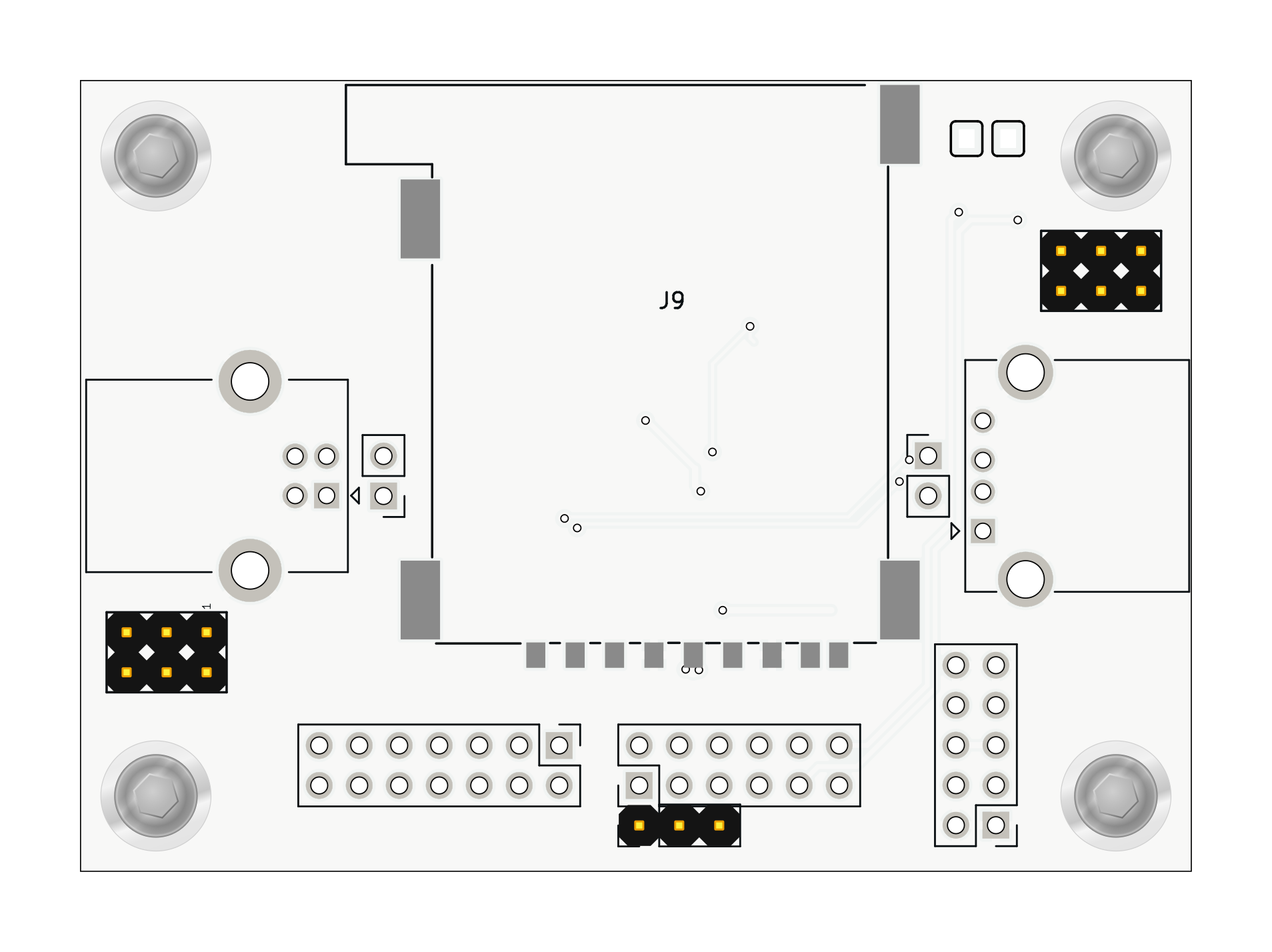
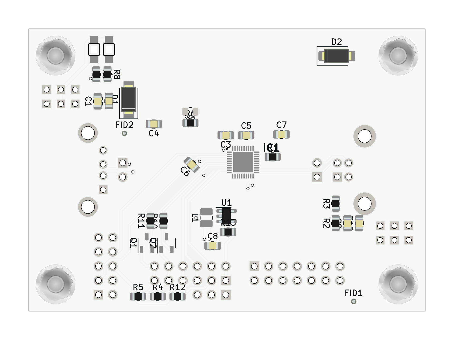
USBSDREADER01 is an open-source printed circuit board by mlab-modules, from the mlab-modules/USBSDREADER01 repository on GitHub. It is a 2-layer board of 70.6 × 50.3 mm with 49 parts on 44 nets, routed with 182 tracks and 13 vias.
It is built around the MAX14502AETL+ and TS5A4594DBV. Its parts include 13 resistors, 11 connectors, 10 capacitors, 4 diodes and 2 ICs.
This module is designed to interface USB devices with SD cards, utilizing the MAX14502AETL integrated circuit. The MAX14502AETL supports both full-speed USB communication (12Mbps) for bridget devices and Hi-Speed USB communication (480Mbps) as SDcard reader, providing a versatile solution for various USB to SD card reading applications.
Power Supply:
USB Connection:
SD Card Connection:
I2C Configuration:
Operation Modes:
For detailed electrical characteristics and operational guidance, refer to the MAX14502AETL Datasheet.
For further assistance, visit MLAB or contact our support team at support@mlab.cz.
| Qty | Value | Footprint | References |
|---|---|---|---|
| 6 | 10k | Resistor_SMD:R_0805_2012Metric | R2, R3, R4, R5, R12, R13 |
| 6 | R_Small | Resistor_SMD:R_0805_2012Metric | R6, R7, R8, R9, R10, R11 |
| 5 | C_Small | Capacitor_SMD:C_0805_2012Metric | C3, C4, C5, C6, C7 |
| 3 | 10uF | Capacitor_SMD:C_0805_2012Metric | C1, C8, C9 |
| 2 | 100nF | Capacitor_SMD:C_0805_2012Metric | C2, C10 |
| 2 | BZV55C-5,6V | Diode_SMD:D_SMA | D1, D2 |
| 2 | Fiducial | Fiducial:Fiducial_0.5mm_Mask1mm | FID1, FID2 |
| 2 | HEADER_1x02 | Connector_PinHeader_2.54mm:PinHeader_1x02_P2.54mm_Vertical | J10, J11 |
| 2 | HOLE | Mlab_Mechanical:MountingHole_3mm | M3, M4 |
| 2 | HOLE M3 | Mlab_Mechanical:MountingHole_3mm | M1, M2 |
| 2 | LED | Mlab_D:LED_1206_mill | D3, D4 |
| 2 | NPN | Package_TO_SOT_SMD:SOT-23-3 | Q1, Q2 |
| 1 | 1uH | Inductor_SMD:L_1008_2520Metric | L1 |
| 1 | 3.3V | Mlab_Pin_Headers:Straight_2x03 | J1 |
| 1 | 6.19k | Resistor_SMD:R_0805_2012Metric | R1 |
| 1 | HEADER_1x02 | Connector_PinHeader_2.54mm:PinHeader_1x03_P2.54mm_Vertical | J8 |
| 1 | HEADER_2x04_PARALLEL | Connector_PinHeader_2.54mm:PinHeader_2x06_P2.54mm_Vertical | J7 |
| 1 | HEADER_2x05_PARALLEL | Connector_PinHeader_2.54mm:PinHeader_2x05_P2.54mm_Vertical | J6 |
| 1 | HEADER_2x07_PARALLEL | Connector_PinHeader_2.54mm:PinHeader_2x07_P2.54mm_Vertical | J5 |
| 1 | MAX14502AETL+ | Mlab_IO:QFN40P500X500X80-41N | IC1 |
| 1 | SD_Card-FPS009-4200-0 | Mlab_CON:FPS009-4200-0 | J9 |
| 1 | TS5A4594 | Package_TO_SOT_SMD:SOT-23-5 | U1 |
| 1 | USB_A | Connector_USB:USB_A_CONNFLY_DS1095-WNR0 | J3 |
| 1 | USB_B | Connector_USB:USB_B_Lumberg_2411_02_Horizontal | J2 |
| 1 | VBUS | Mlab_Pin_Headers:Straight_2x03 | J4 |
It measures 70.6 × 50.3 mm and has 2 copper layers, 1.6 mm thick.
49 parts, built around the MAX14502AETL+ and TS5A4594DBV. The full list of its parts is on this page, with links to each part's symbol and footprint where PCBKit's library has them.
From the mlab-modules/USBSDREADER01 repository on GitHub, at the commit this page was made from: the board is hw/sch_pcb/USBSDREADER01.kicad_pcb and its schematic hw/sch_pcb/USBSDREADER01.kicad_sch. PCBKit opens the board in the browser, with nothing to install.
Its repository states no licence, so its author keeps all rights: ask mlab-modules before reusing the design.
mlab-modules/BATDATUNIT01
Multiple parallel Li-ion 18650 battery cell module with BMS and data storage with MCU control.

UniversalScientificTechnologies/SPACEDOS02
Solid-state PIN diode dosimeter for manned spacecraft. Liulin detector replacement.

UniversalScientificTechnologies/SPACEDOS01
Silicon diode dosimeter optimized for spacecraft dosimetry


mlab-modules/PCRD06
Sample and hold circuit for photomultiplier pulse signal processig


