
6 layers95 × 55 mm
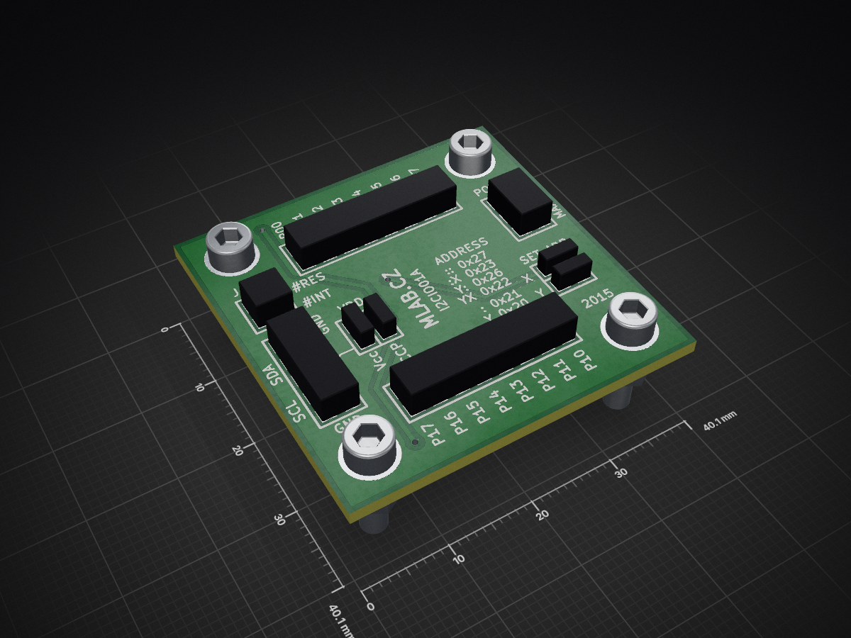
 mlab-modules/I2CIO01
GPIO expander with I²C interface; 16-bit I/O, configurable ports, polarity inversion.
I2CIO01 is an open-source printed circuit board by mlab-modules, from the mlab-modules/I2CIO01 repository on GitHub. It is a 2-layer board of 40.1 × 40.1 mm with 38 parts on 25 nets, routed with 213 tracks and 3 vias.
It is built around the TCA6416APW. Its parts include 21 resistors, 13 connectors, 2 capacitors, 1 IC and 1 diode. It belongs with the interfaces and adapters boards of this library.
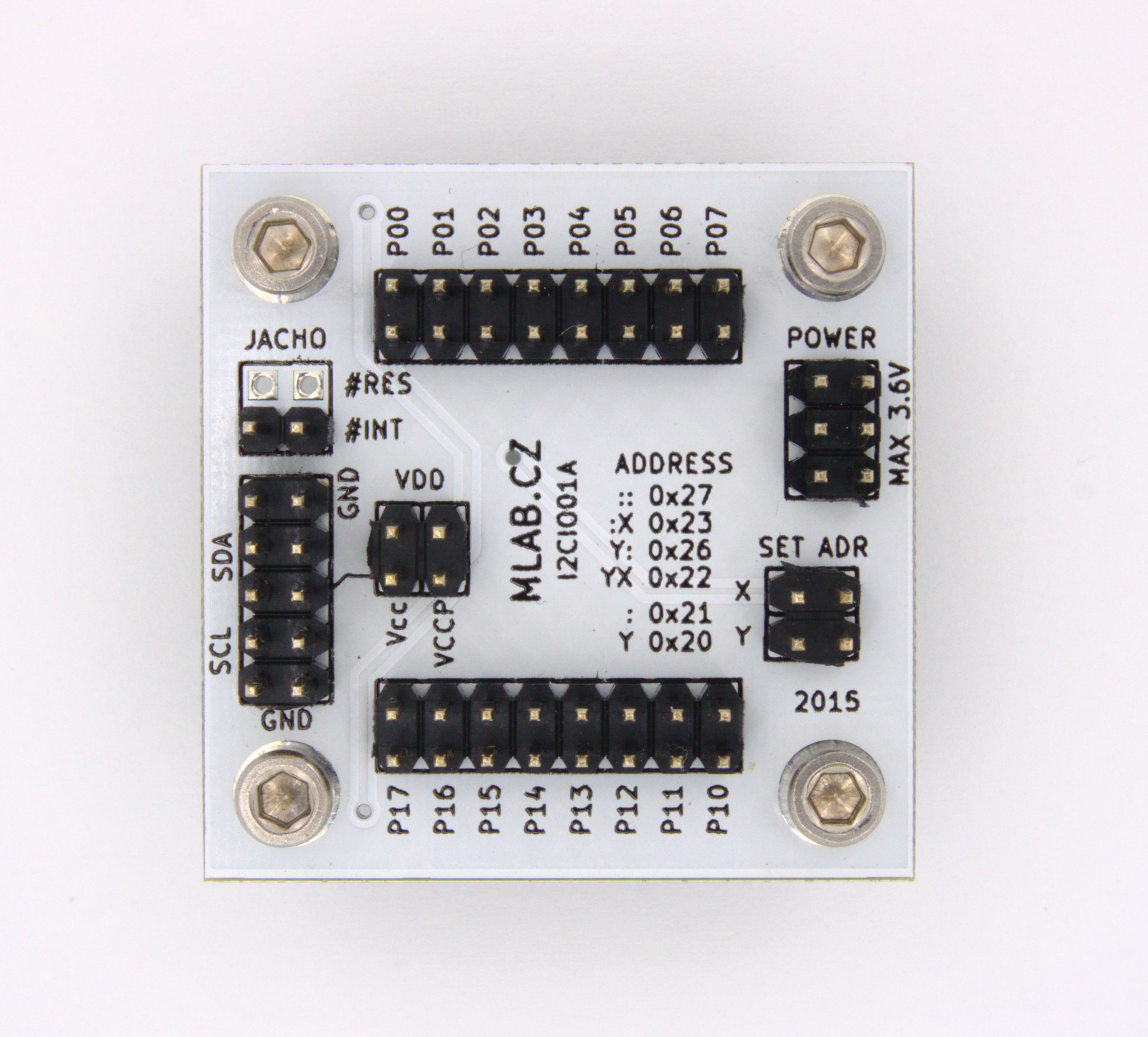
The I2CIO01 module is a GPIO expander designed for operation in the range of 1.65 to 5.5 V. It provides general-purpose remote I/O expansion via the I²C interface. The module comprises two 8-bit Configurable, Input Ports, Output Port, and Polarity Inversion registers.
| Parameter | Value | Note |
|---|---|---|
| Power Supply | Max. 3.6 V | |
| ICs Used | TCA6416A or TCA9535 | |
| Interface bus | I²C | Frequency up to 400 kHz |
| Main Usage | I²C IO expander | |
| Dimensions | 40.13 x 40.13 x 16 mm | Height above the baseboard |
The module's design and layout files can be found in the hw/sch_pcb directory. The board is designed using KiCad.
| Designator | Type | Package | Quantity |
|---|---|---|---|
| J3 | JUMP_3X2 | Pin_Header_Straight_2x03 | 1 |
| R1, R2, R3, ... | 10k | SMD-0805 | 13 |
| U1 | TCA6416A | TSSOP-28 | 1 |
| J8, J5 | CONN1_2 | Pin_Header_Straight_1x02 | 2 |
| P1, P2, P3, P4 | MountingHole_3mm | 4 | |
| J1 | JUMP_2X2 | Pin_Header_Straight_2x02 | 1 |
| J2 | JUMP_5X2 | Pin_Header_Straight_2x05 | 1 |
| J6, J7 | JUMP_8X2 | Pin_Header_Straight_2x08 | 2 |
| J4, J9 | CONN_2 | Pin_Header_Straight_1x02 | 2 |
| C1 | 10uF | SMD-0805 | 1 |
| C2 | 100nF | SMD-0805 | 1 |
| D1 | BZV55C-3,6V | Diode-MiniMELF_Standard | 1 |
For more detailed information on each component, please refer to their respective datasheets:
Contributions are welcome! Please fork this repository and submit a pull request with your changes.
For more information, visit the MLAB website or contact us at support@mlab.cz.
| Qty | Value | Footprint | References |
|---|---|---|---|
| 13 | 10k | SMD_Packages:SMD-0805 | R1, R2, R3, R4, R5, R7, R9, R11, R13, R15, R16, R18, R24 |
| 8 | - | SMD_Packages:SMD-0805 | R6, R8, R10, R12, R14, R17, R19, R20 |
| 4 | _ | Dira:MountingHole_3mm | P1, P2, P3, P4 |
| 2 | CONN1_2 | Hrebinky:Pin_Header_Straight_1x02 | J5, J8 |
| 2 | CONN_2 | Hrebinky:Pin_Header_Straight_1x02 | J4, J9 |
| 2 | JUMP_8X2 | Hrebinky:Pin_Header_Straight_2x08 | J6, J7 |
| 1 | 100nF | SMD_Packages:SMD-0805 | C2 |
| 1 | 10uF | SMD_Packages:SMD-0805 | C1 |
| 1 | BZV55C-3,6V | MLAB_D:Diode-MiniMELF_Standard | D1 |
| 1 | JUMP_2X2 | Hrebinky:Pin_Header_Straight_2x02 | J1 |
| 1 | JUMP_3X2 | Hrebinky:Pin_Header_Straight_2x03 | J3 |
| 1 | JUMP_5X2 | Hrebinky:Pin_Header_Straight_2x05 | J2 |
| 1 | TCA6416A | IO:TSSOP-28 | U1 |
It measures 40.1 × 40.1 mm and has 2 copper layers, 1.6 mm thick.
38 parts, built around the TCA6416APW. The full list of its parts is on this page, with links to each part's symbol and footprint where PCBKit's library has them.
From the mlab-modules/I2CIO01 repository on GitHub, at the commit this page was made from: the board is hw/sch_pcb/I2CIO01.kicad_pcb and its schematic hw/sch_pcb/I2CIO01.kicad_sch. PCBKit opens the board in the browser, with nothing to install.
Its repository states no licence, so its author keeps all rights: ask mlab-modules before reusing the design.

joeycastillo/The-Open-Book
For details on how to build, test and use Open Book, I've made documentation available here.


hackclub/OnBoard
💡 Join 1,000 teenagers and make your first PCB with a $100 grant!


Ardumower/ardumower
Develop an open source robotic lawn mower (HW+SW reference platform)

CRImier/MyKiCad
My KiCad boards. Can't be bothered uploading individually anymore, so here you go.
