
2 layers38 × 56 mm

 mkhairyx/iOS-MoonLamp3
A Moon Lamp based on an ESP32 controlled using the iOS Home app.
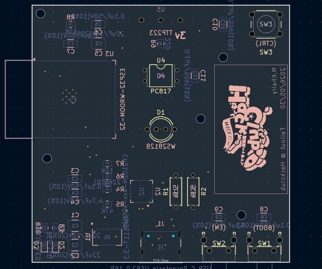
IOS MoonLamp is an open-source printed circuit board by mkhairyx, from the mkhairyx/iOS-MoonLamp repository on GitHub. It is a 2-layer board of 60 × 60 mm with 33 parts on 69 nets.
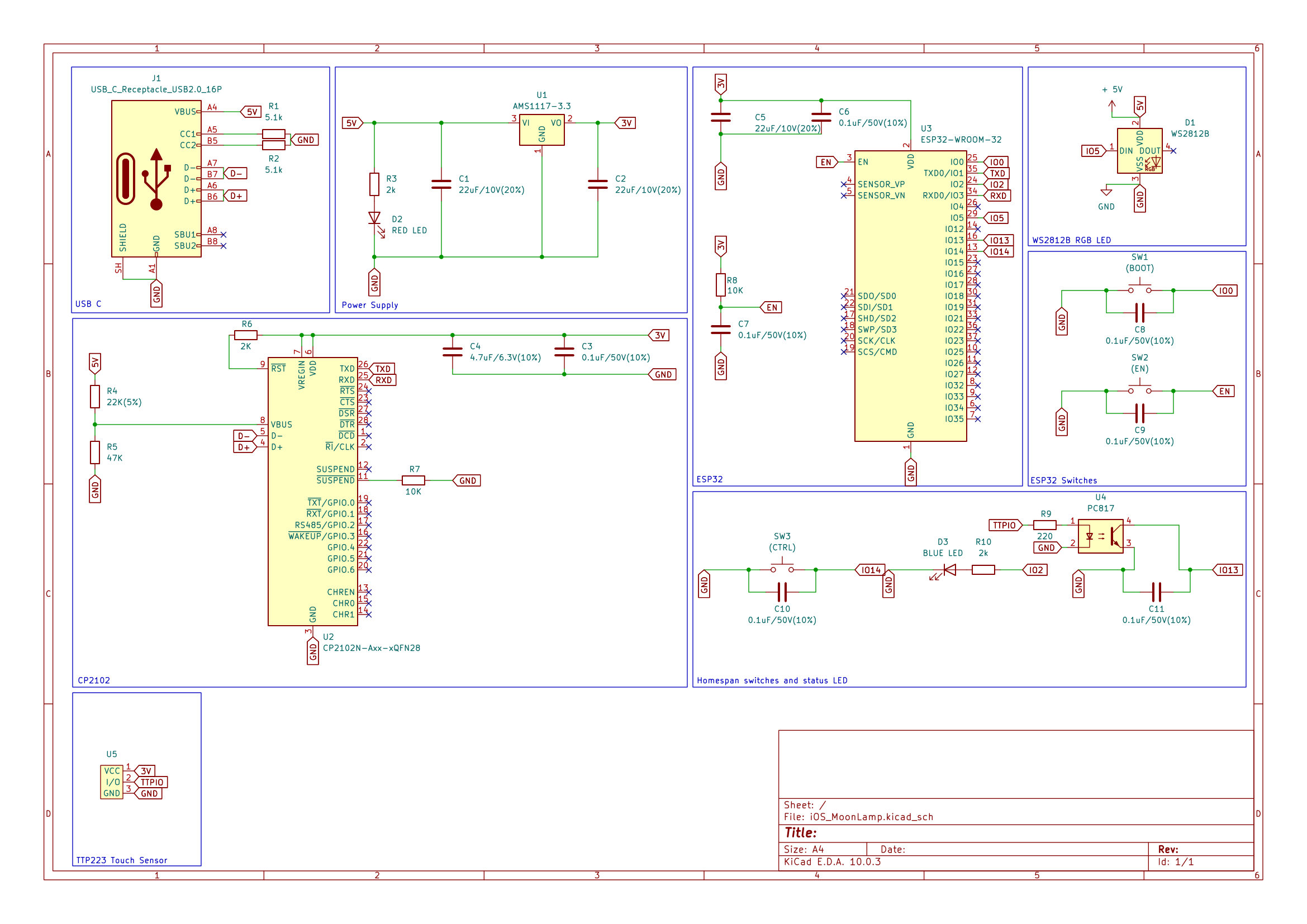
It is built around the ESP32-WROOM-32, AMS1117-3.3 and WS2812B. Its parts include 11 capacitors, 10 resistors, 5 ICs, 3 diodes and 3 switches. It belongs with the lEDs and displays boards and the ESP32 boards of this library.


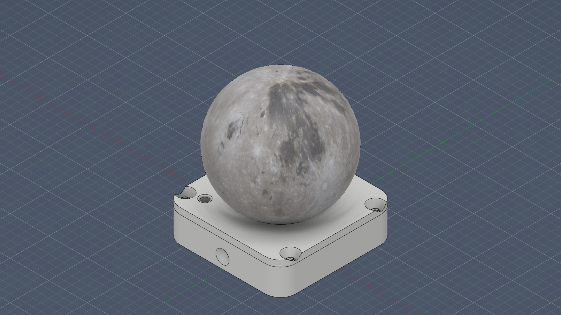
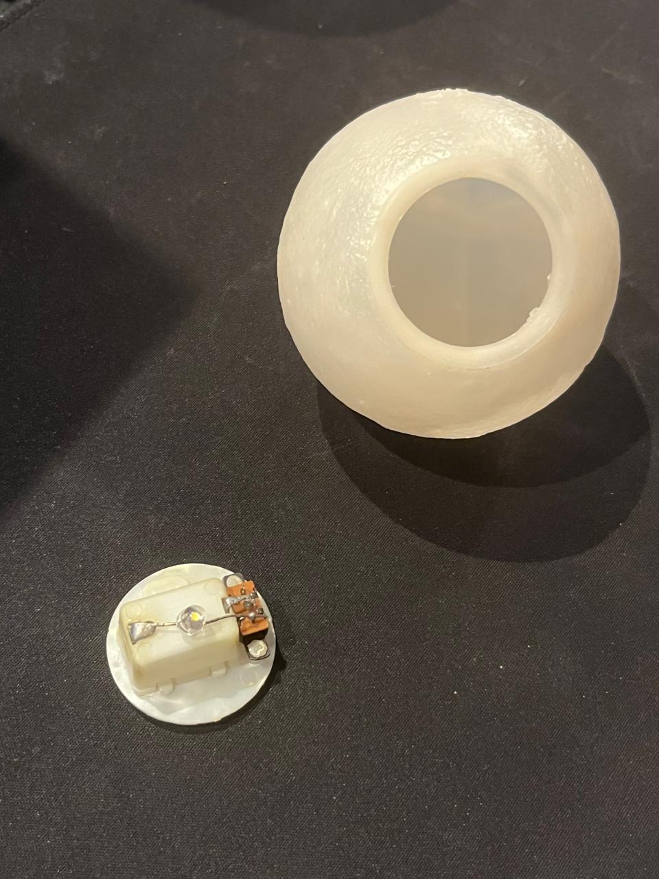
Bought a battery powered Moon lamp a few years ago, and it was cool back then but now it’s boring that I have to turn it on and off manually every night. So I removed the insides of it and made it powered with an ESP32 controlled by the iOS Home app.
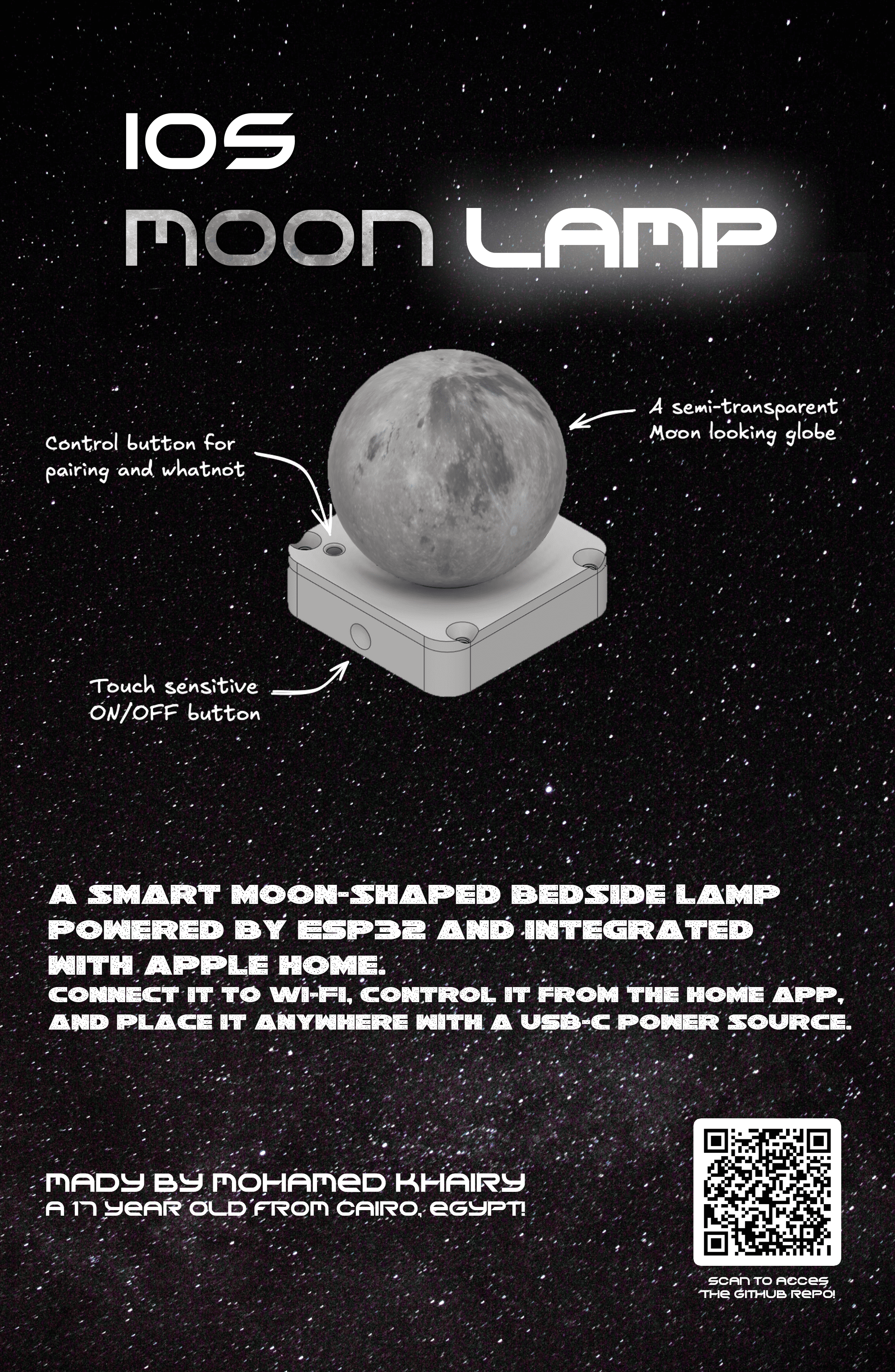
High resolution poster available here.
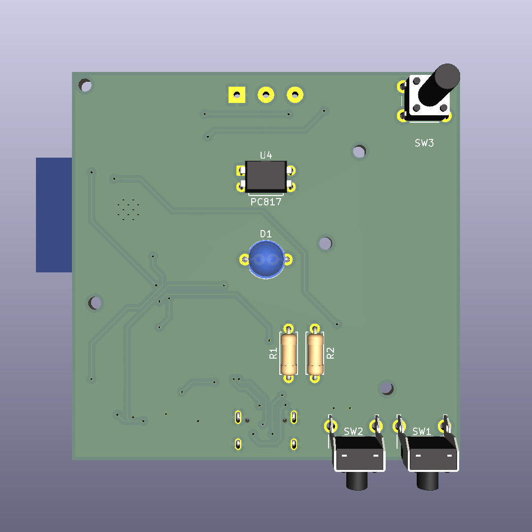
Here's how the PCB looks like:
 And here's the gerber view for it:
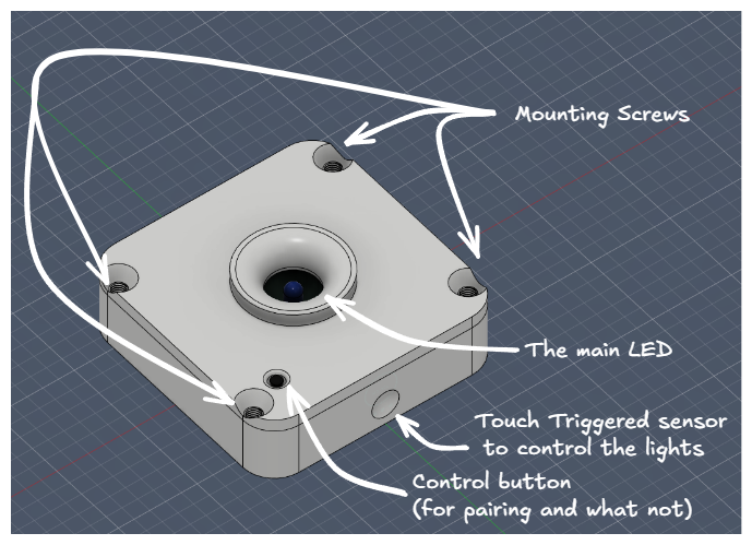
The case is held together with four M5 screws.
Check Step_Files to see step files.
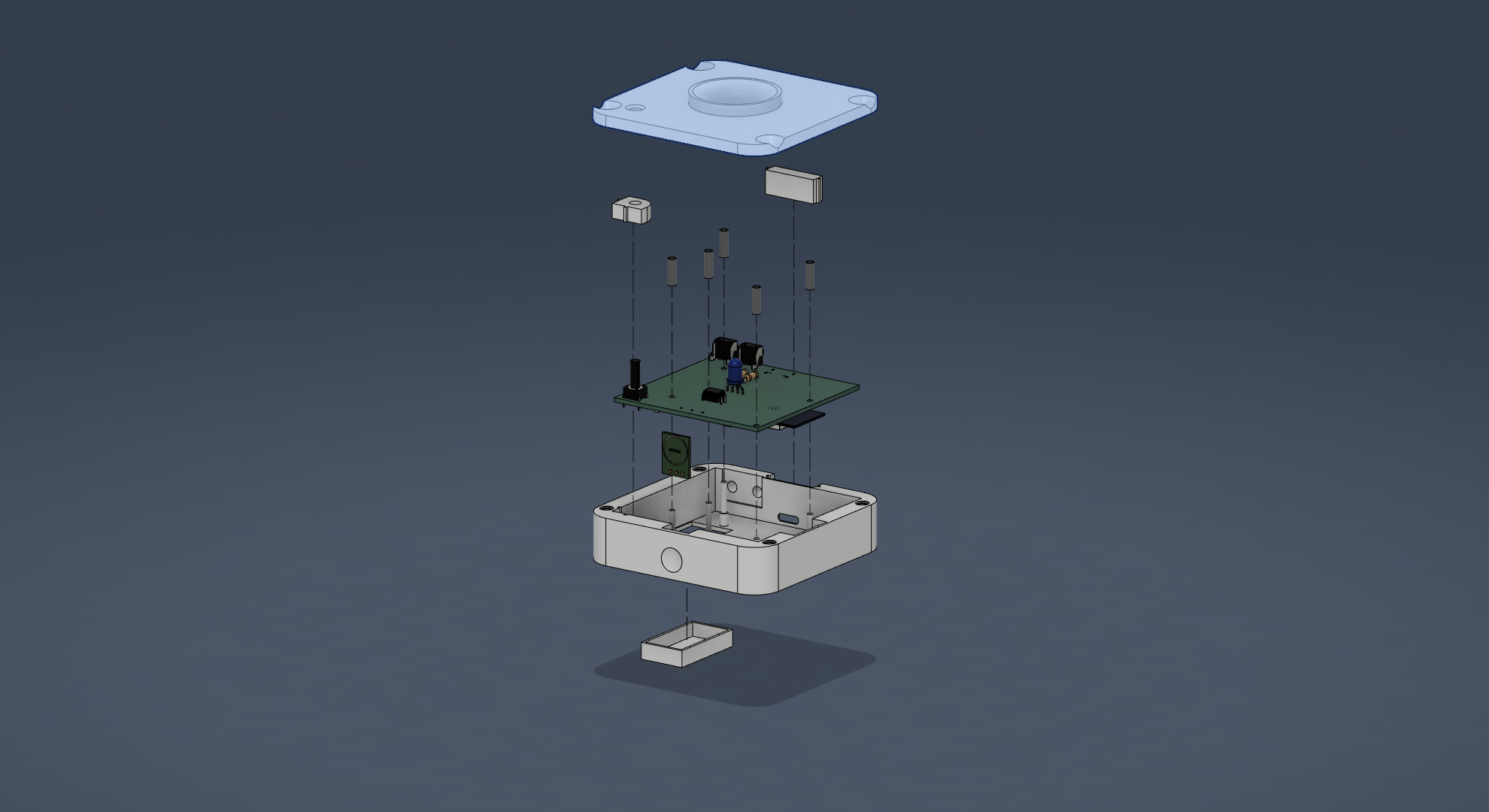
This video shows how to assemble and disassemble the case:
https://github.com/user-attachments/assets/3fa87b10-48f1-4240-b7dd-df9781dbfde8
If you want to edit the code, compile it yourself, then flash it; you can download the arduino sketch and the required libraries here.
If you want to flash the firmware as is, you can download it here.
You can use ESPWebTool to flash the firmware directly to the ESP32 using your browser.
The device is powered by a USB-C and does not have a battery, so please make sure that it's connected to a stable USB-C power source. The device shows wether it's powered on or not through the Red LED on the back near the USB-C port.
The device shows it's status through the Blue Status LED on the back near the USB-C port. Refer to HomeSpan's documentation on HomeSpan Device Status to be able to identify different states.
The CLI can be used to setup the device, change the WI-FI credentials, or factory reset the system.1 You can use the CLI through the onboard USB-C port on the back. Use a baud rate of 9600 for serial communication.
The Control Button can be used to put the device in Command Mode and select different actions. Refer to HomeSpan's documentation on Device Command Mode to know how to use it
Available as a .csv file here
(Pricing for the enclosure and the PCB will depend on where the stuff are made)
Nori (PCB only): $19.05
metanoia (Case only): $5.77
JLCPCB (both PCB and Case): $32.42
The TTP 223 module is connected to the main PCB using three wires.
The 3D printed case, the PCB, and the Moon itself (the lamp) are not included in the BOM, but their costs are shown in Orders from different manufacturers.
The Moon Lamp it self was salvaged from an old lamp, so it costs nothing, therefore it wasn't included in the BOM.
Made and designed by @mkhairyx.
Supported by Fallout and Hack Club.
Powered by HomeSpan
Check the The HomeSpan Command-Line Interface (CLI) to be able to use the device's CLI through the onboard USB-C port. ↩
| Qty | Value | Footprint | References |
|---|---|---|---|
| 7 | 0.1uF/50V(10%) | Capacitor_SMD:C_1206_3216Metric_Pad1.33x1.80mm_HandSolder | C3, C6, C7, C8, C9, C10, C11 |
| 3 | 22uF/10V(20%) | Capacitor_SMD:C_1210_3225Metric_Pad1.33x2.70mm_HandSolder | C1, C2, C5 |
| 2 | 10K | Resistor_SMD:R_0805_2012Metric_Pad1.20x1.40mm_HandSolder | R7, R8 |
| 2 | 2k | Resistor_SMD:R_0805_2012Metric_Pad1.20x1.40mm_HandSolder | R3, R10 |
| 2 | 5.1k | Resistor_THT:R_Axial_DIN0207_L6.3mm_D2.5mm_P7.62mm_Horizontal | R1, R2 |
| 1 | (BOOT) | Button_Switch_THT:SW_Tactile_SPST_Angled_PTS645Vx58-2LFS | SW1 |
| 1 | (CTRL) | Button_Switch_THT:SW_PUSH_6mm_H13mm | SW3 |
| 1 | (EN) | Button_Switch_THT:SW_Tactile_SPST_Angled_PTS645Vx58-2LFS | SW2 |
| 1 | 220 | Resistor_SMD:R_0805_2012Metric_Pad1.20x1.40mm_HandSolder | R9 |
| 1 | 22K(5%) | Resistor_SMD:R_0805_2012Metric_Pad1.20x1.40mm_HandSolder | R4 |
| 1 | 2K | Resistor_SMD:R_0805_2012Metric_Pad1.20x1.40mm_HandSolder | R6 |
| 1 | 4.7uF/6.3V(10%) | Capacitor_SMD:C_1206_3216Metric_Pad1.33x1.80mm_HandSolder | C4 |
| 1 | 47K | Resistor_SMD:R_0805_2012Metric_Pad1.20x1.40mm_HandSolder | R5 |
| 1 | AMS1117-3.3 | Package_TO_SOT_SMD:SOT-223-3_TabPin2 | U1 |
| 1 | BLUE LED | LED_SMD:LED_0603_1608Metric_Pad1.05x0.95mm_HandSolder | D3 |
| 1 | CP2102N-Axx-xQFN28 | Package_DFN_QFN:QFN-28-1EP_5x5mm_P0.5mm_EP3.35x3.35mm | U2 |
| 1 | ESP32-WROOM-32 | RF_Module:ESP32-WROOM-32 | U3 |
| 1 | PC817 | Package_DIP:DIP-4_W7.62mm | U4 |
| 1 | RED LED | LED_SMD:LED_0603_1608Metric_Pad1.05x0.95mm_HandSolder | D2 |
| 1 | USB_C_Receptacle_USB2.0_16P | Connector_USB:USB_C_Receptacle_GCT_USB4105-xx-A_16P_TopMnt_Horizontal | J1 |
| 1 | WS2812B | LED_THT:LED_D5.0mm-4_RGB_Wide_Pins | D1 |
| 1 | ~ | Custom:Untitled | U5 |

skrmsh/skirmish-hardware
Skirmish Hardware © 2022-2023 by Ole Lange is licensed under CC BY-NC-SA 4.0. To view a copy of this license, visit http://creativecommons.org/licenses/by-nc-sa/4.0/

OpenLaundry/wifi-rfid-uhf-reader
Portable long range RFID uhf reader with WIFI based on esp32


lluisestape-upc/T8-Sequencer
16-step ESP32 groovebox: two-layer 290x210 mm KiCad board, DRC-clean and fabrication-ready, with the Python scripts that generated and repaired it


It measures 60 × 60 mm and has 2 copper layers, 1.6 mm thick.
33 parts, built around the ESP32-WROOM-32, AMS1117-3.3 and WS2812B. The full list of its parts is on this page, with links to each part's symbol and footprint where PCBKit's library has them.
From the mkhairyx/iOS-MoonLamp repository on GitHub, at the commit this page was made from: the board is source/KiCad - PCB/iOS_MoonLamp/_restore_backup_2026-05-30T03-58-17-070/iOS_MoonLamp.kicad_pcb and its schematic source/KiCad - PCB/iOS_MoonLamp/_restore_backup_2026-05-30T03-58-17-070/iOS_MoonLamp.kicad_sch. PCBKit opens the board in the browser, with nothing to install.
Its repository states no licence, so its author keeps all rights: ask mkhairyx before reusing the design.