Unix60pcb
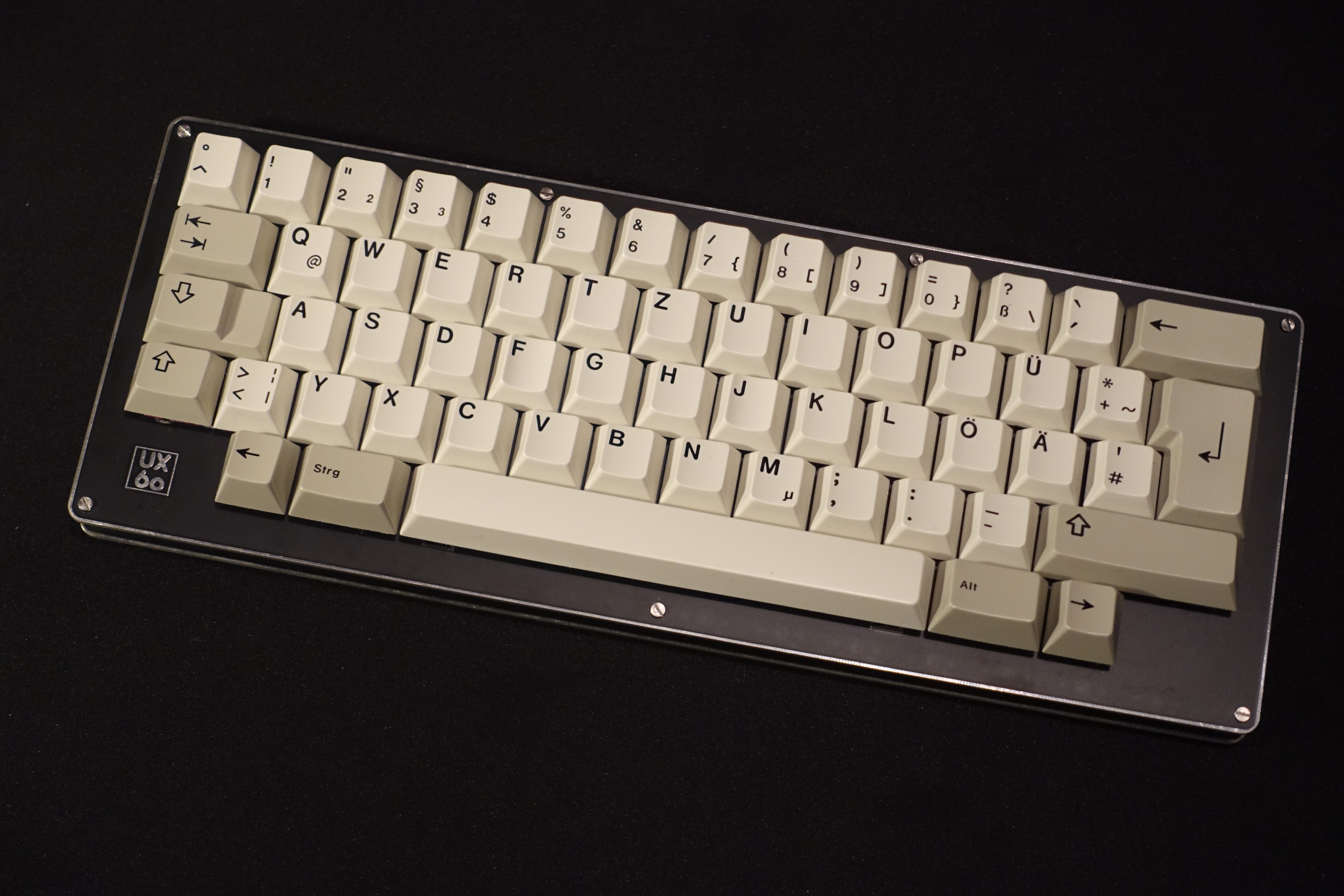
HHKB Layouted and QMK compatible keyboard built from FR4
- Size
- 285.8 × 107.2 mm
- Copper layers
- 2
- Thickness
- 1.6 mm
- Parts
- 137
- Nets
- 87
- Pads
- 1,021
- Tracks, vias
- 1,465, 23
- Routed
- Yes
- KiCad
- KiCad 5 (file 20171130)
- Created
- 9 Dec 2020
- Updated
- 17 Sep 2021
Overview
Unix60pcb is an open-source printed circuit board by mkdl, from the mkdl/Unix60 repository on GitHub, published under the GPL-3.0 licence. It is a 2-layer board of 285.8 × 107.2 mm with 137 parts on 87 nets, routed with 1,465 tracks and 23 vias.
Its parts include 68 switches, 63 diodes, 1 IC and 1 connector. It belongs with the keyboards and input boards and the AVR (ATmega, ATtiny) boards of this library.
README
README.mdUnix60
The Unix60 is a budget FR4 keyboard designed to make a HHKB-style layout available to everyone with as few compromises as possible.
If you have any questions or need help, please join the FR4 Discord: https://discord.gg/z7mpQX5YJQ
Disclaimer: You must follow this guide in the order it is written. Assembling stuff in the wrong order (specifically your Pro Micro or Elite C and its headers) will likely result in you having to desolder components and significantly increase the amount of time it takes to assemble. I am not responsible for boards damaged during assembly. I highly recommend you read through the entire guide before starting assembly.
Assembly:
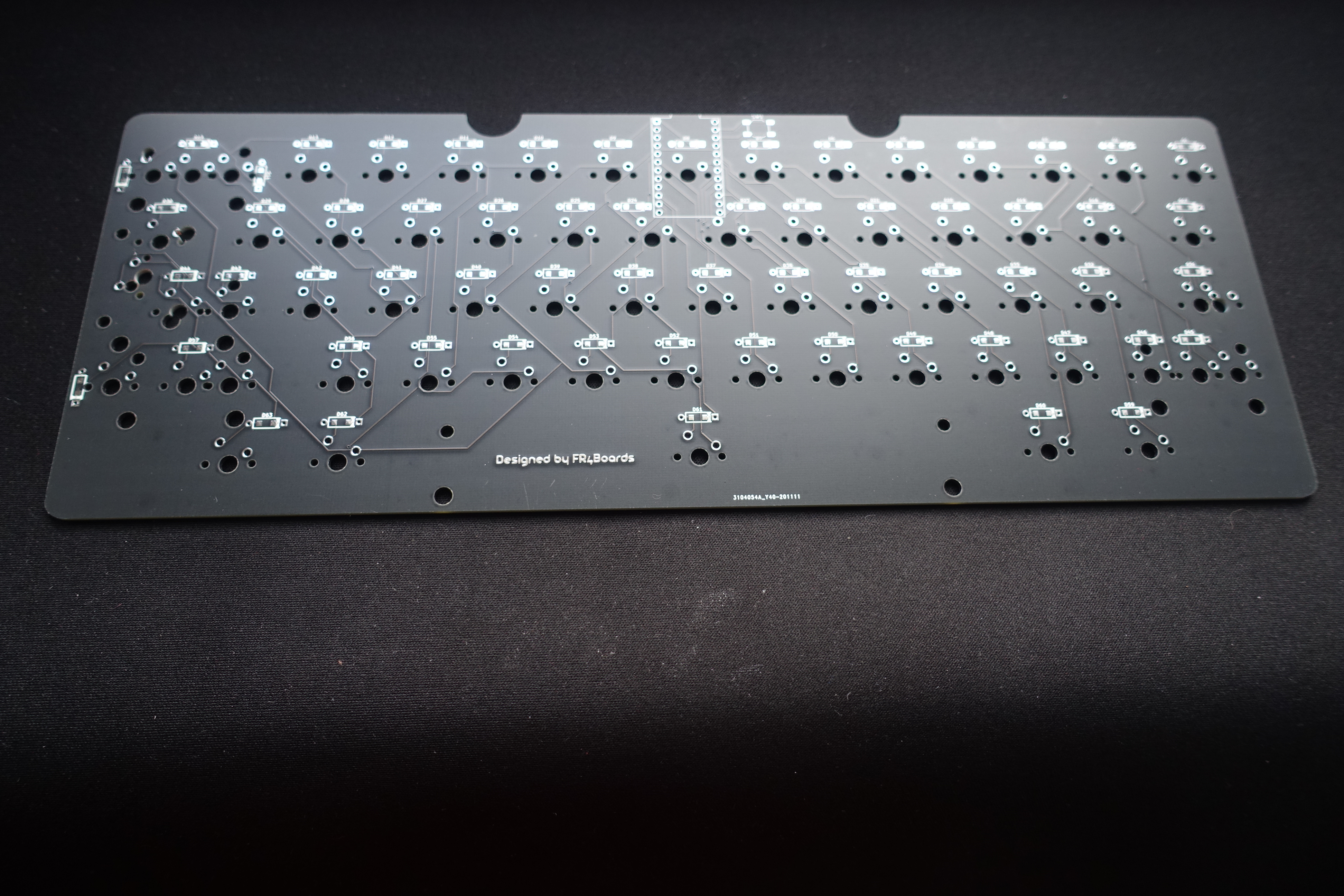
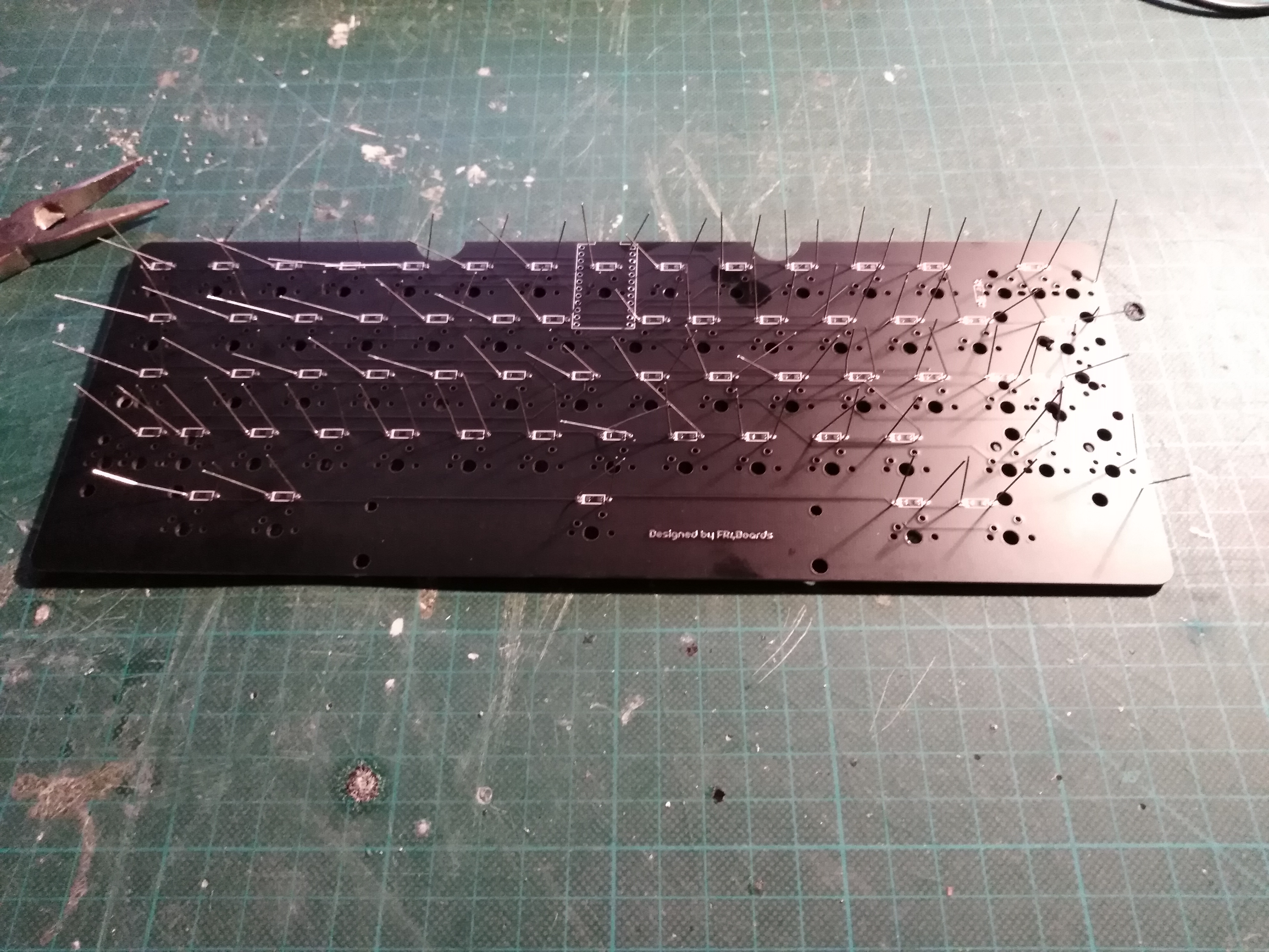
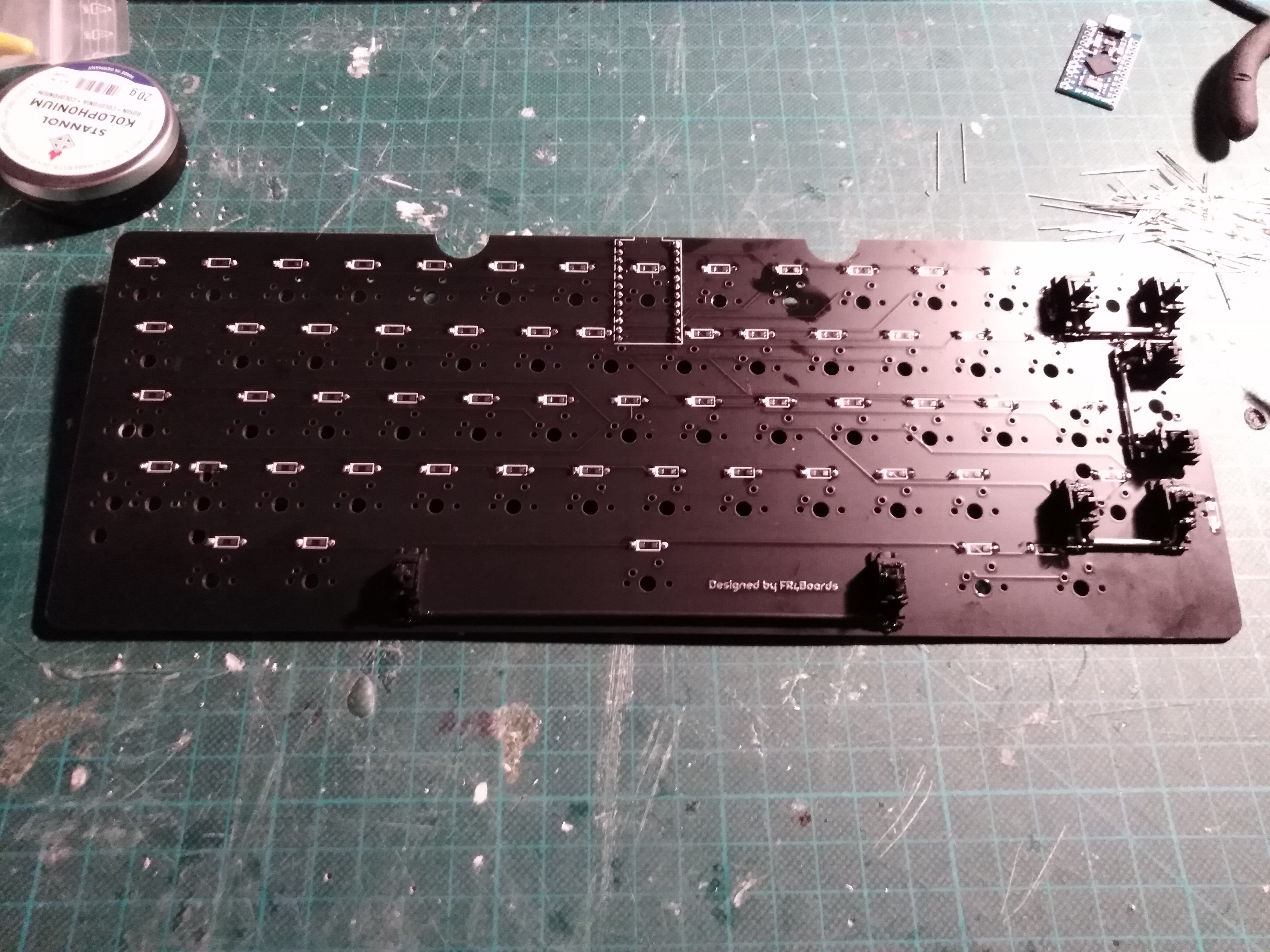
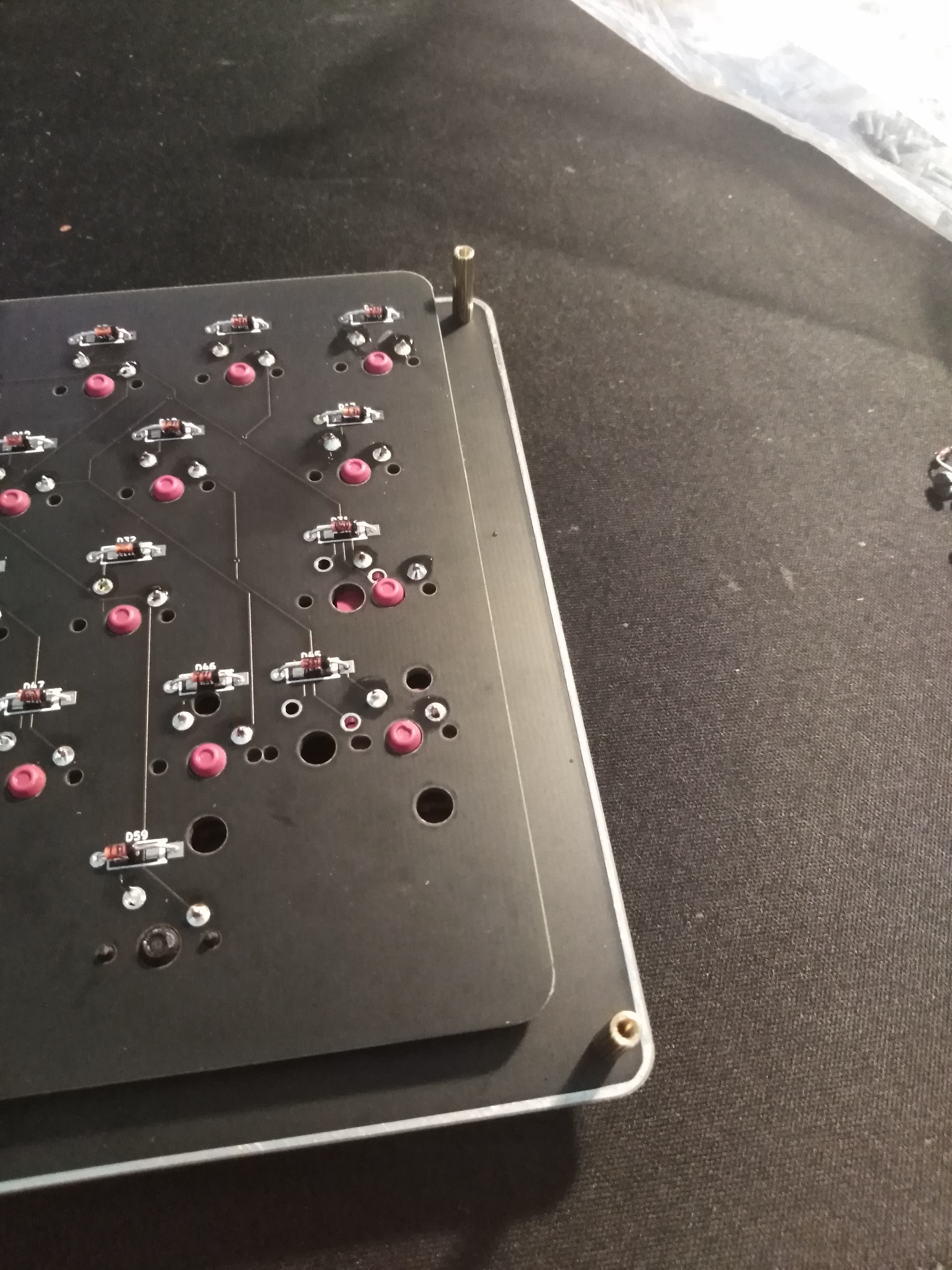
1. Put the diodes through the PCB so the legs stick out the front side of the board and so the diode is flush with the back, making sure the black line on the diode faces the square pad:

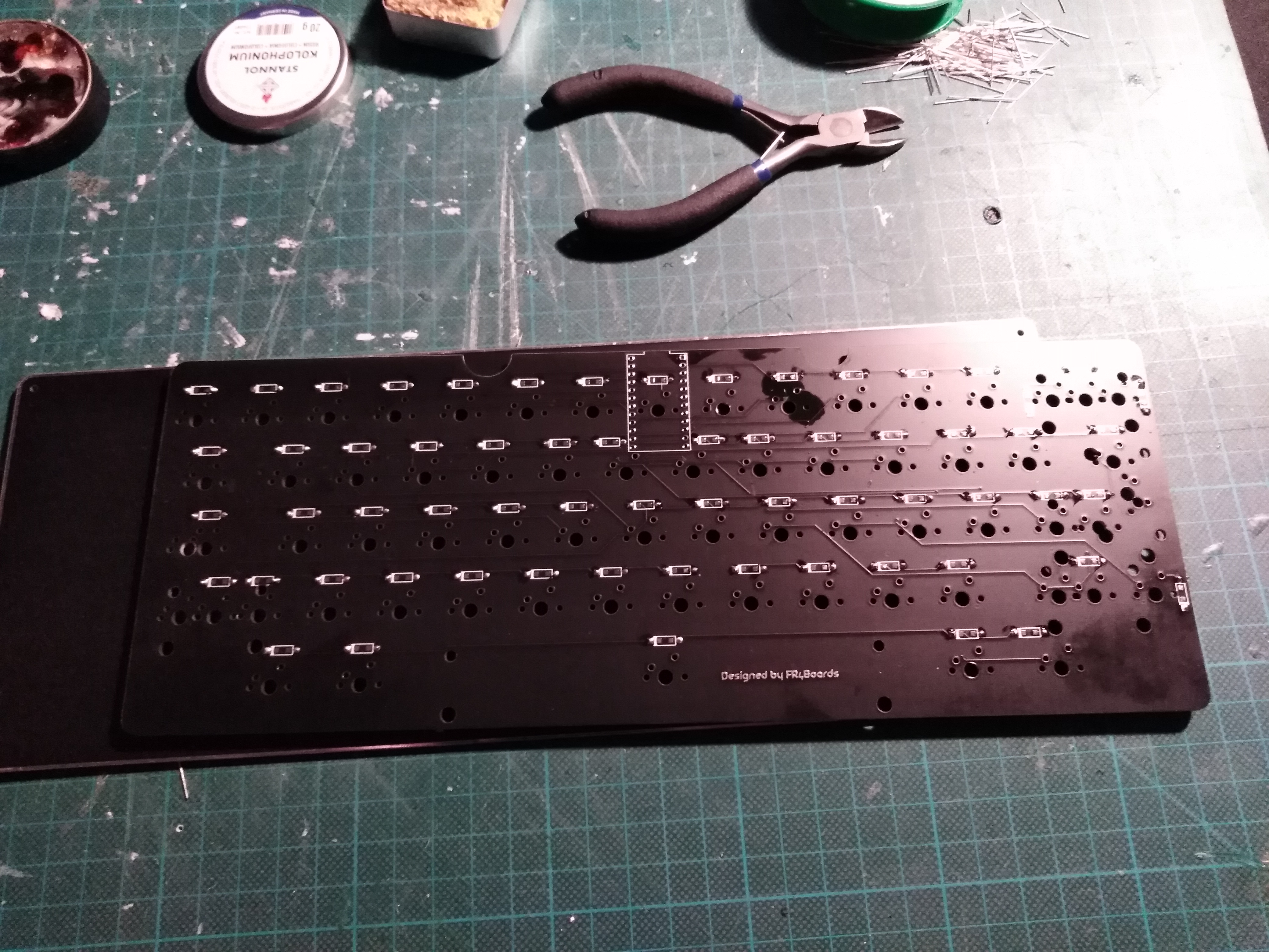
2. Solder from the back and snip the legs:

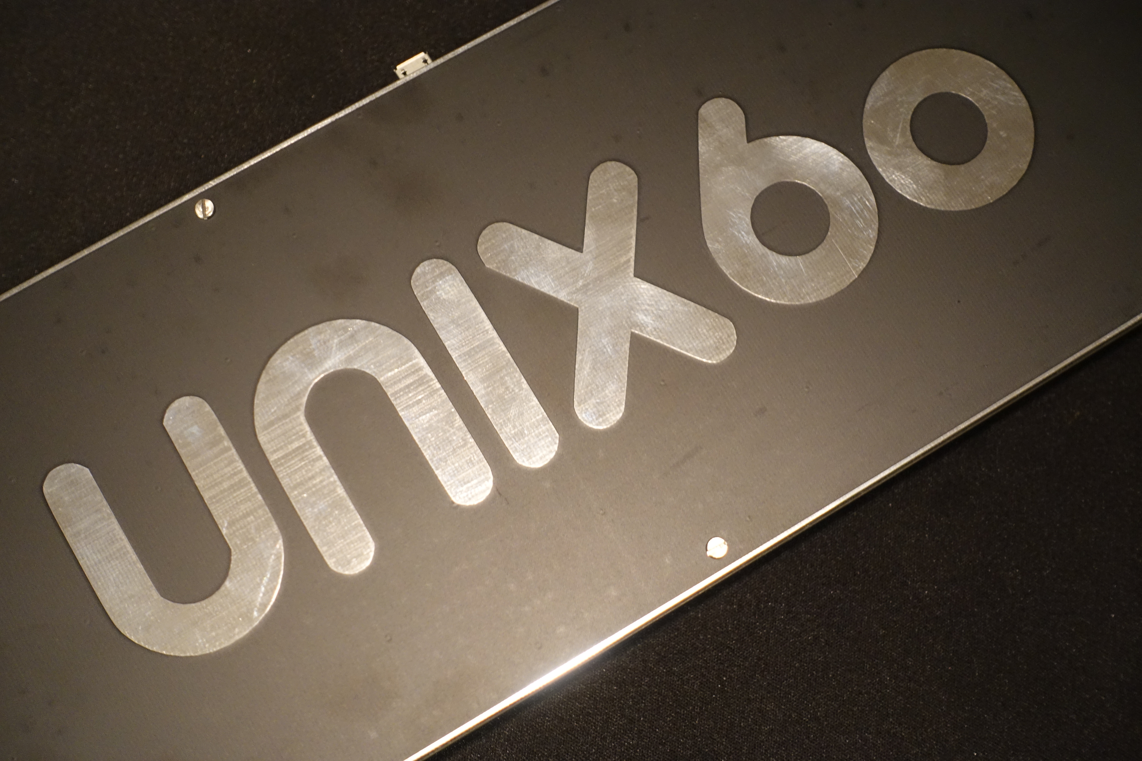
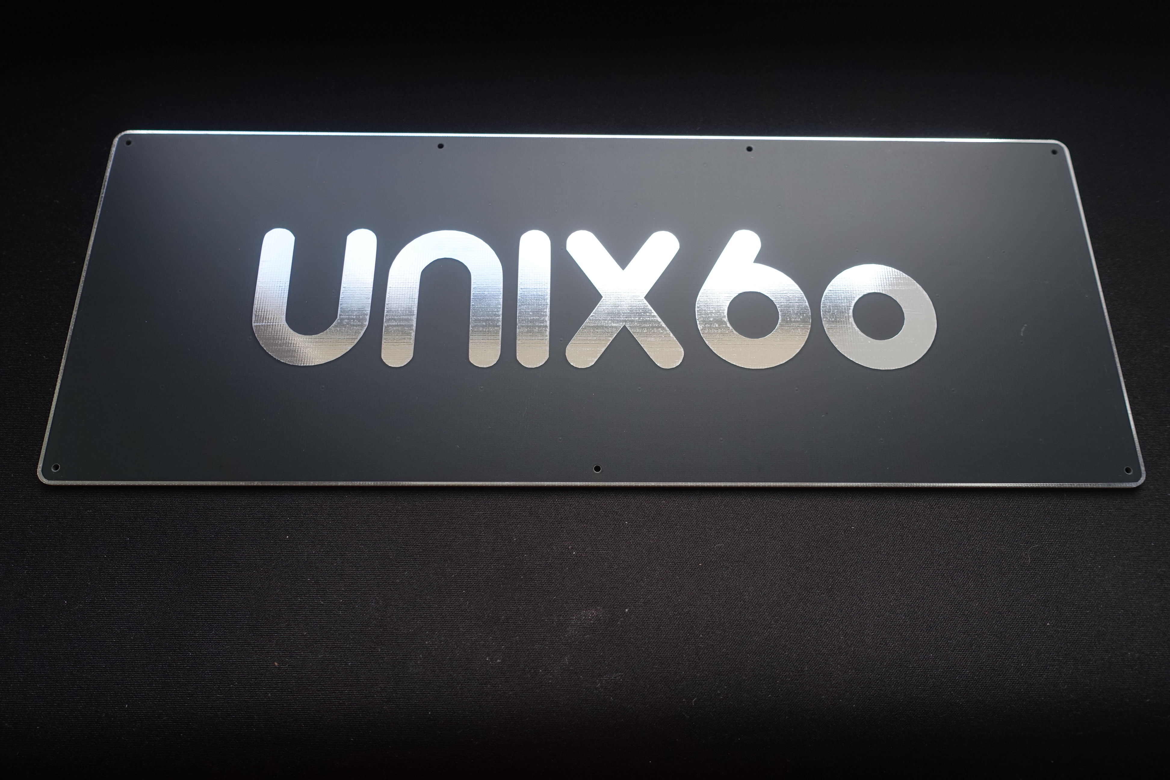
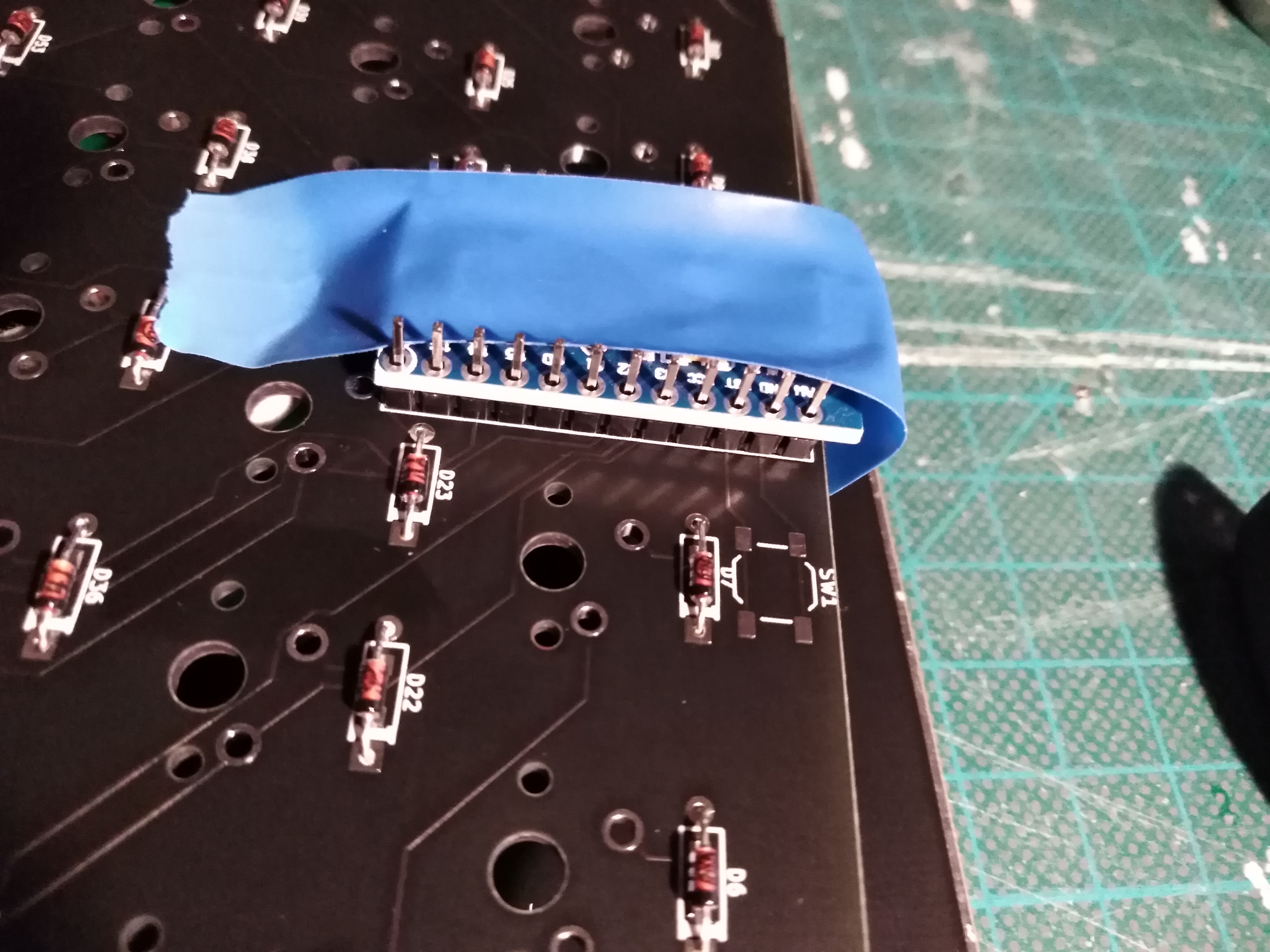
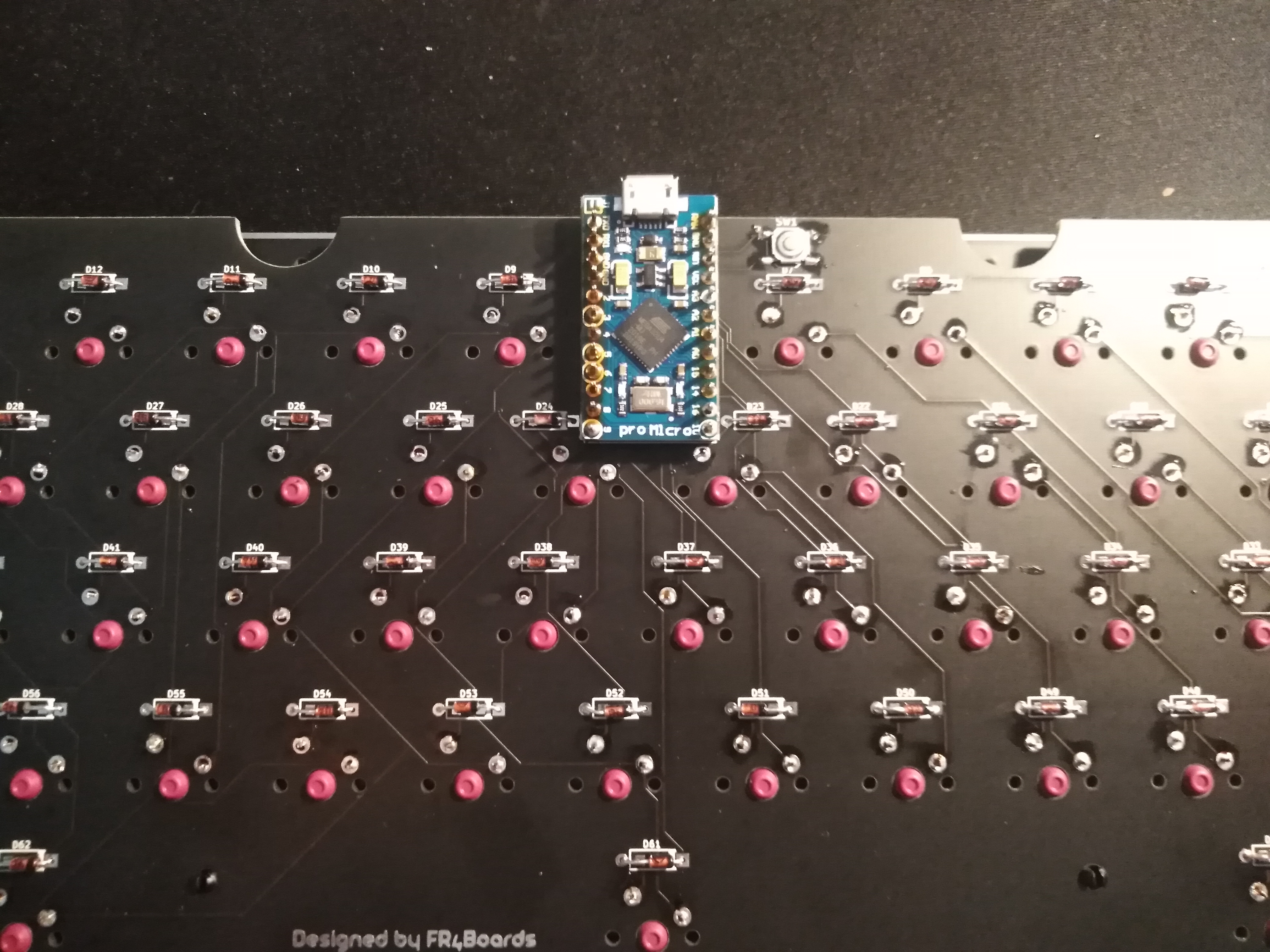
3. Place your Pro Micro or Elite C onto its pin headers and sit it into the board so the Pro Micro is on the back of the PCB (the side with the Unix60 logo) and tape it down to temporarily hold it in place. This helps align the pin headers properly. It doesn't matter whether you put the shorter pins on the PCB or the longer ones; either way, you will have to snip the longer ones once you've soldered them in. DO NOT SOLDER THE PRO MICRO OR ELITE C TO THE PIN HEADERS YET!

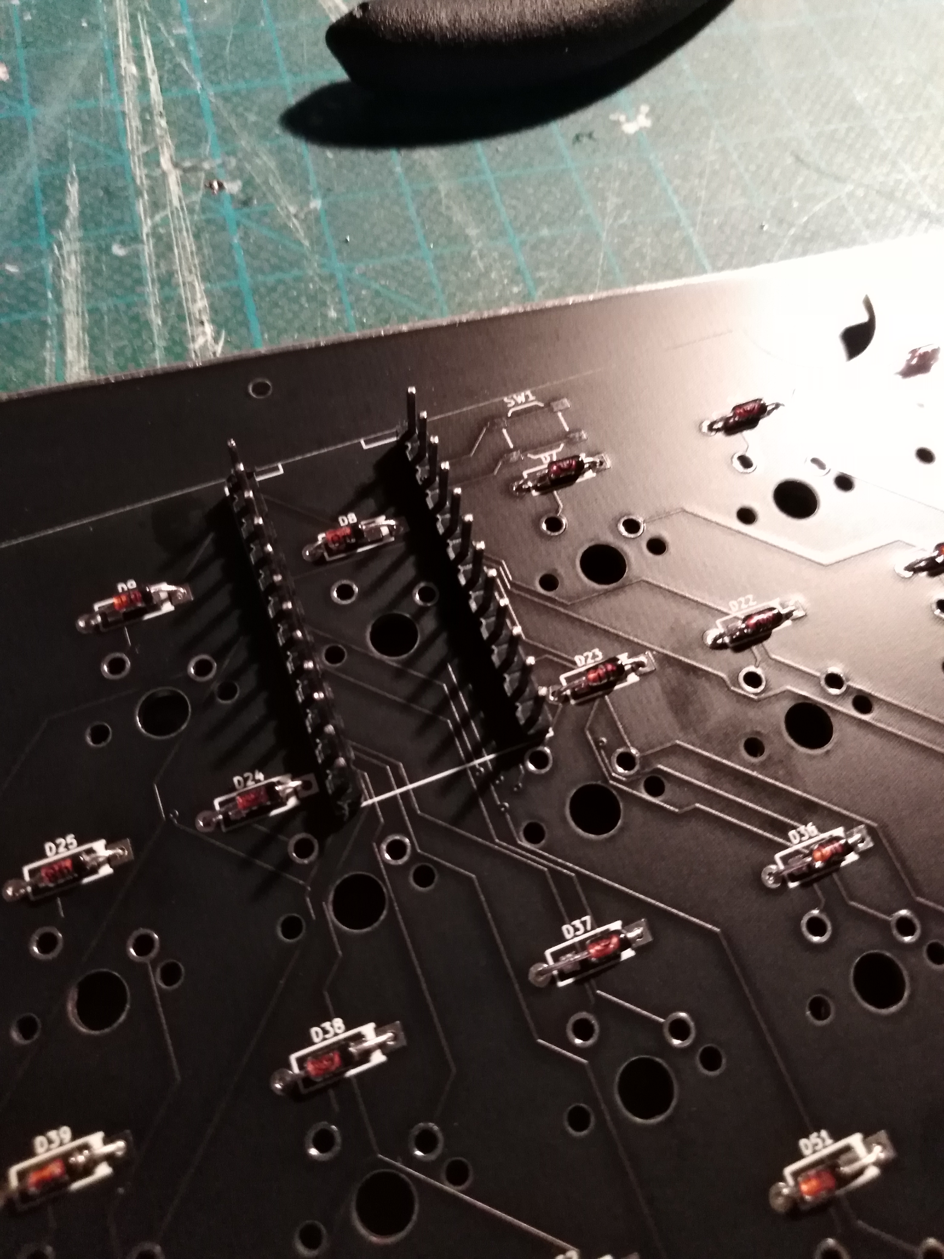
4. Solder in the pin headers from the front side of the PCB. Do not solder the Pro Micro or Elite C yet, just the headers!

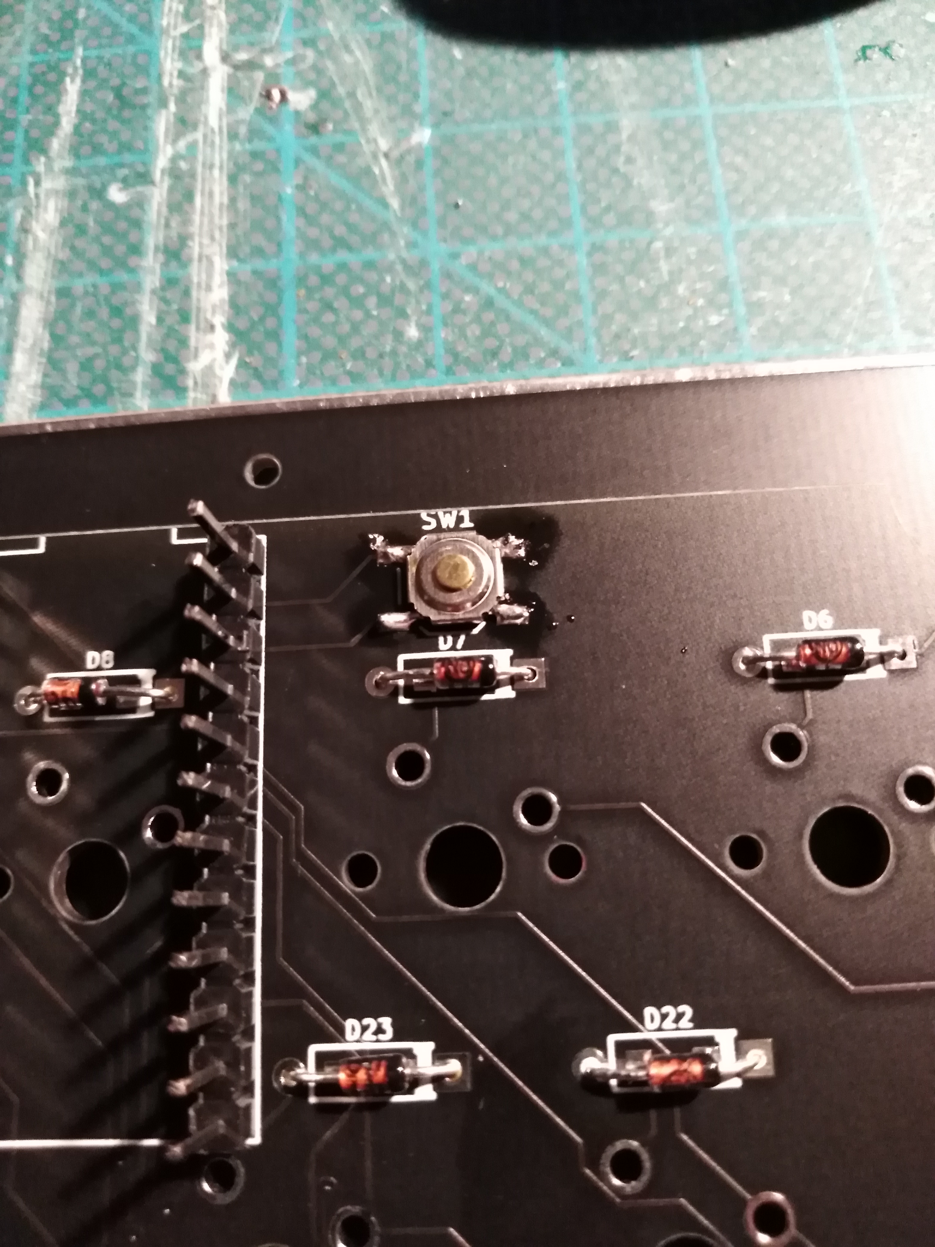
5. Solder your reset button to the PCB

Note: If you've lost your reset button, don't worry. Shorting the two pads closest to the edge of the PCB or the two closest to the inside will reset your controller. After all, that's all the button does :)
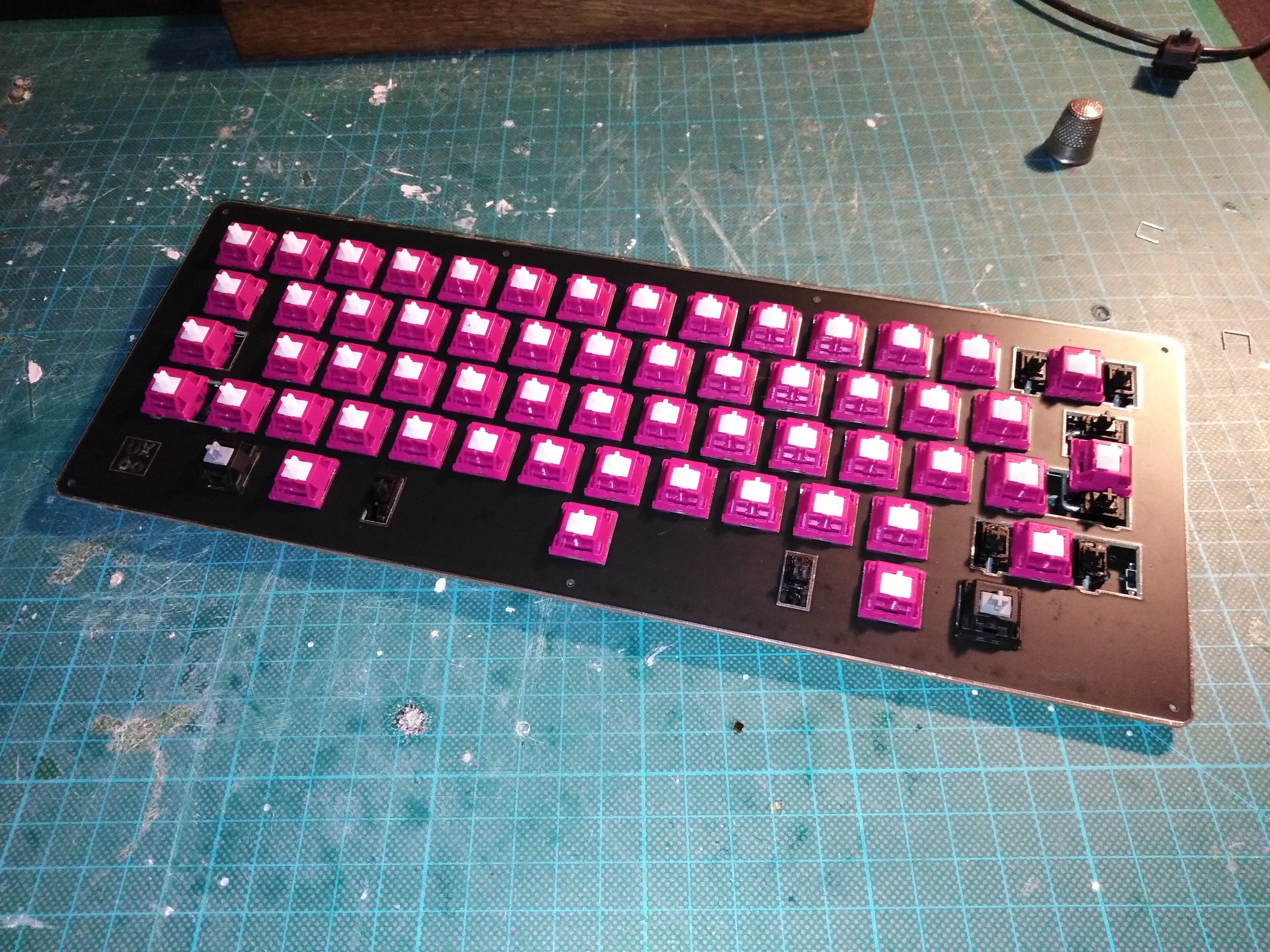
8. Attach your stabs to the PCB (do not be afraid to push, you won't break it)

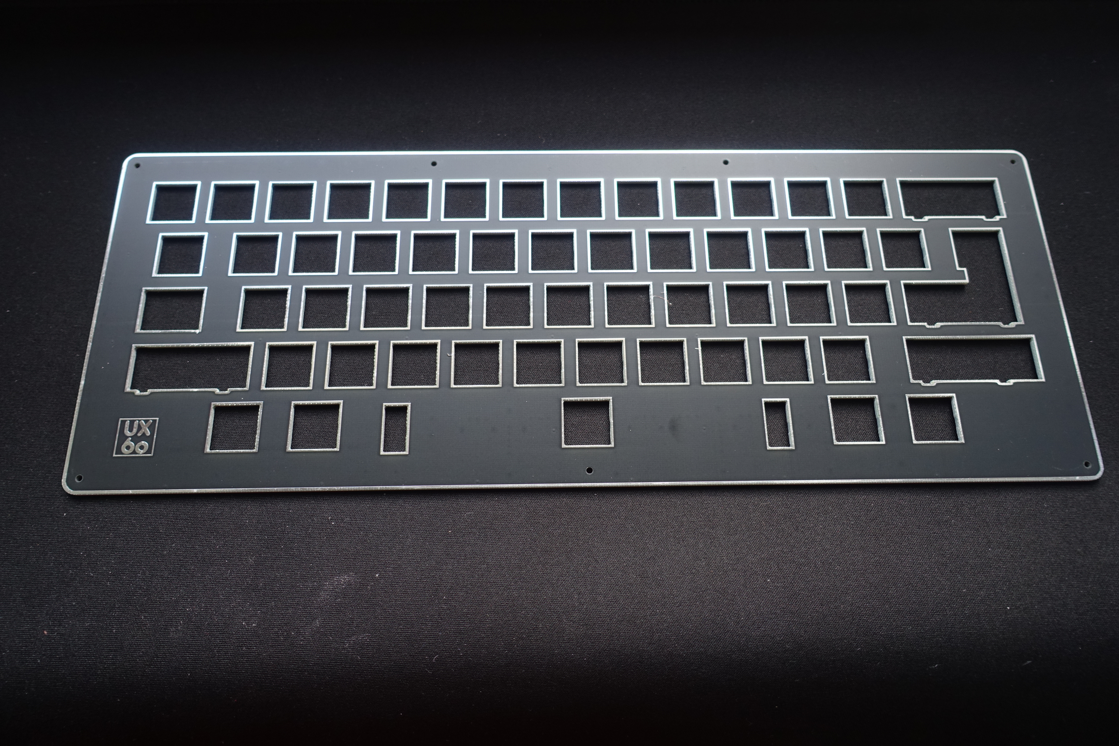
9. Mount switches in the corner of the plate to align it, then lower the plate onto the PCB

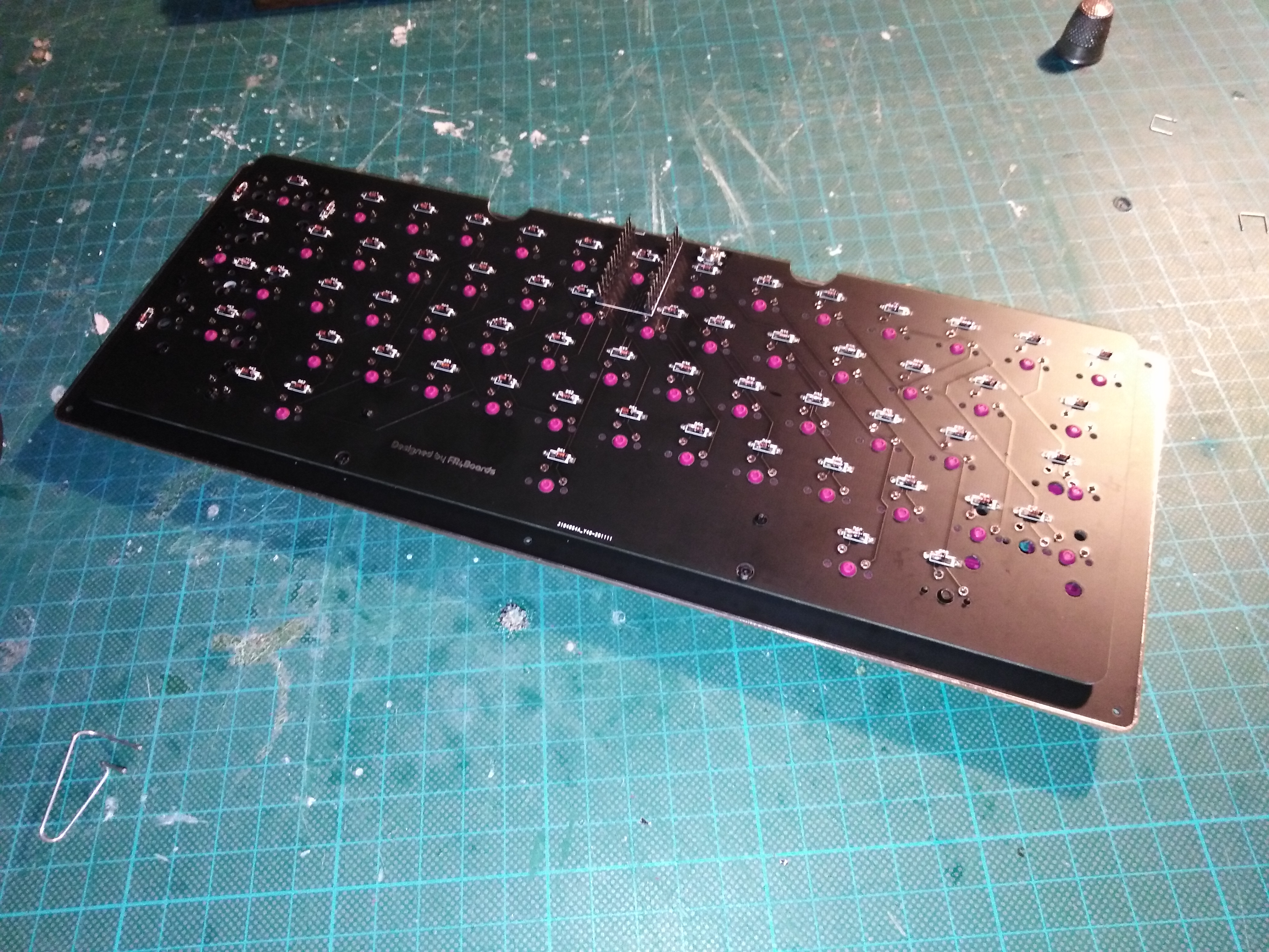
10. Add the rest of your switches and solder them all in

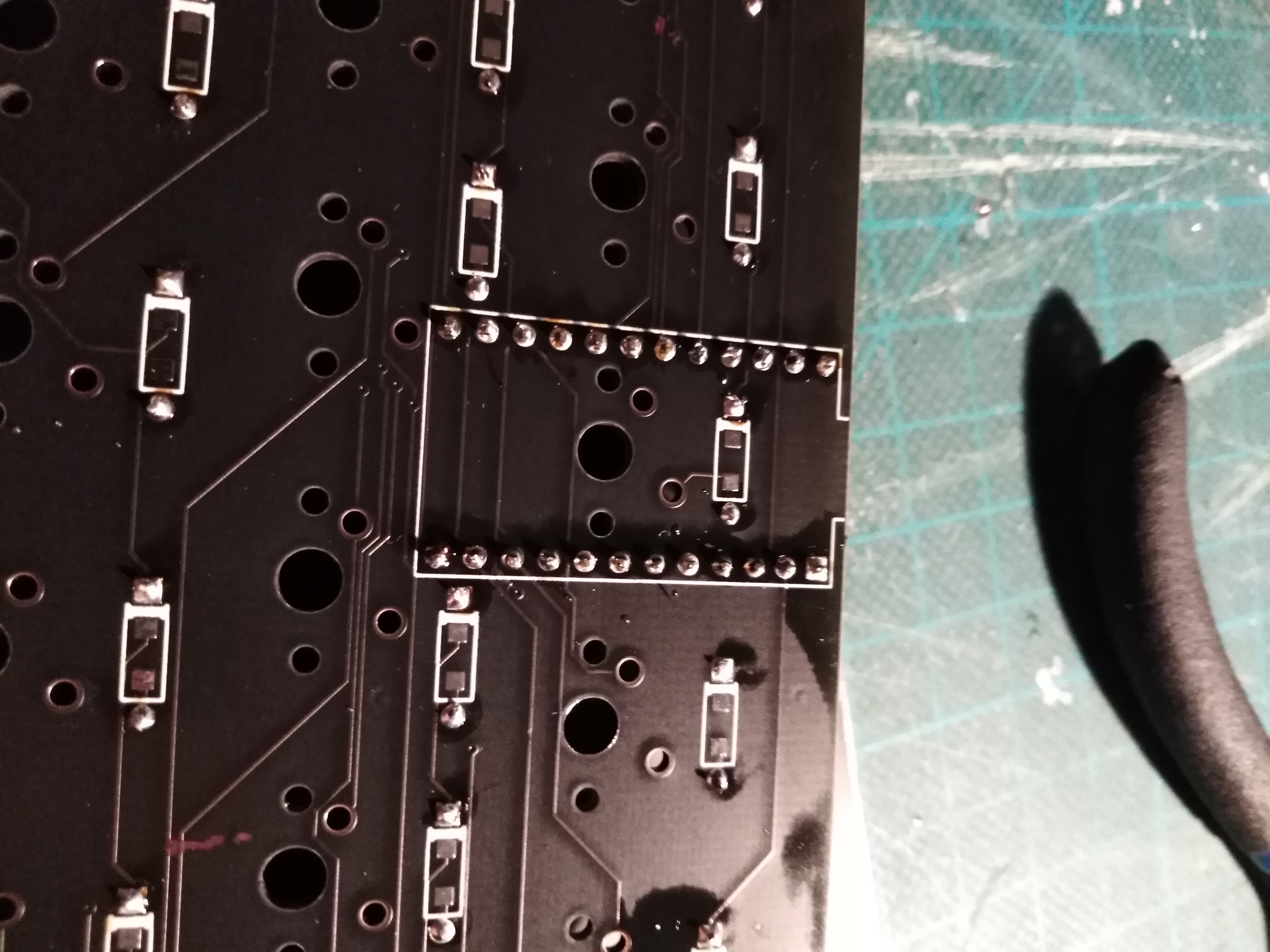
11. Once you have verified that all your diodes, switches, and Pro Micro or Elite C pin headers are soldered properly, you can now solder your Pro Micro or Elite C onto the pin headers:

12. Attach standoffs to the bottom of the plate using screws from the other side

13. Screw on the bottom plate
Flashing instructions for Linux:
1. Plug your Pro Micro or Elite C in
2. Open up the QMK configurator and create your desired layout
3. Download the .json file (on the left, next to keymap.json)
4. Open up a command line
5. Type qmk flash /path/to/layout.json (obviously replacing the file path with the path to your downloaded layout) and follow any additional instructions
One thing to note is that you can compile a .hex file on the configurator and flash that with avrdude, however, I prefer the method outlined above.
Flashing instructions for Windows:
Please keep in mind that I do not run Windows on my own system and cannot 100% verify this flashing procedure will work or if it requires any other configuration. I highly recommend you check the QMK docs if something is not working.
1. Plug your Pro Micro or Elite C in
2. Open up the QMK configurator and create your desired layout
3. Click "compile" in the upper right, and once it's done, download the .hex by clicking "firmware"
4. Open up QMK toolbox and load your downloaded .hex
5. Click "flash" and follow any additional instructions
Parts
137| Qty | Value | Footprint | References |
|---|---|---|---|
| 63 | D | Canadian_Footprints:D_SOD123_axial-dual | D1, D2, D10, D11, D12, D13, D14, D15, D16, D17, D18, D19, D20, D21, D22, D23 +47 |
| 53 | KEYSW | MX_Only:MXOnly-1U-NoLED | K1, K2, K10, K11, K12, K13, K14, K16, K18, K19, K20, K21, K22, K23, K24, K25 +37 |
| 4 | KEYSW | MX_Only:MXOnly-1.5U-NoLED | K17, K30, K60, K62 |
| 2 | KEYSW | MX_Only:MXOnly-1.25U-NoLED | K31-2, K45-2 |
| 2 | KEYSW | MX_Only:MXOnly-2.25U-NoLED | K44, K45 |
| 2 | KEYSW | MX_Only:MXOnly-1.75U-NoLED | K31, K57-2 |
| 2 | LOGO | Logos:Signature_F_Mask | G***, G*** |
| 2 | LOGO | Logos:Signature_F_Cu | G***, G*** |
| 1 | Expansion | Connector_PinSocket_2.54mm:PinSocket_1x04_P2.54mm_Vertical | J1 |
| 1 | KEYSW | MX_Only:MXOnly-ISO-ROTATED-ReversedStabilizers-NoLED | K44-2 |
| 1 | KEYSW | MX_Only:MXOnly-2U-NoLED | K15 |
| 1 | KEYSW | MX_Only:MXOnly-7U-NoLED | K61 |
| 1 | KEYSW | MX_Only:MXOnly-2.75U-NoLED | K57 |
| 1 | ProMicro | Pro_Micro:ProMicro | U1 |
| 1 | Reset | Button_Switch_SMD:SW_SPST_TL3342 | SW1 |
Questions
How big is the Unix60pcb PCB?
It measures 285.8 × 107.2 mm and has 2 copper layers, 1.6 mm thick.
What parts does the Unix60pcb use?
137 parts. The full list of its parts is on this page, with links to each part's symbol and footprint where PCBKit's library has them.
Where can I download the Unix60pcb KiCad files?
From the mkdl/Unix60 repository on GitHub, at the commit this page was made from: the board is PCB/unix60pcb.kicad_pcb. PCBKit opens the board in the browser, with nothing to install.
Can I use the Unix60pcb design in my own project?
Its repository publishes it under the GPL-3.0 licence: you may reuse it on that licence's terms (keep the author's notice, and for a copyleft licence share your changes alike).
Similar boards
- 2 layers134.7 × 120.8 mm

- 2 layers286 × 128 mm

- 2 layers137.9 × 92.7 mm

ErgoTravel
jpconstantineau/ErgoTravel
A Portable Ergonomic Split Keyboard inspired from the ErgoDox, Let's Split and Minidox
137 parts284MIT - 2 layers94.3 × 128.5 mm

- 2 layers155 × 70 mm

Payphone v1
sdylewski/Analog-Redial
A circuit board for old telephones to come back to life. Plug one or two phones in, and you can call the other phone, use bluetooth, connect to others via voip, and do a variety of other things with a plain old rotary…
137 parts46 - 2 layers404.4 × 137.6 mm

C128SX mx
sjgray/CBM-MX-Keyboards
Replacement and enhanced keyboards for Commodore machines
137 parts27 - 2 layers188.9 × 80.8 mm

Pandemonium BLE e7 cutout
calvin-mcd/pandemonium
30% alpha staggered keyboard with big ISO enter and bluetooth support
137 parts26GPL-3.0 - 2 layers99.1 × 99.1 mm

Miasma IO smd
JMHanson4/Miasma_1.03_Revised
1) Updated the footprints and symbols to ones included in KiCAD 5.1.5, or otherwise included the auxillary libraries in the repository.
137 parts23