2 layers127 × 73 mm

 mjhaahr/LED-USB-Hub6
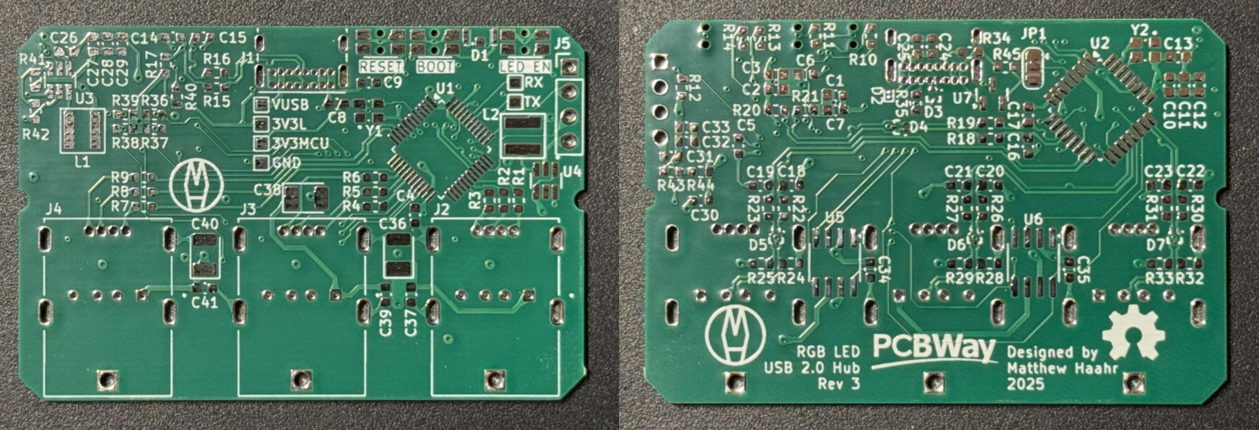
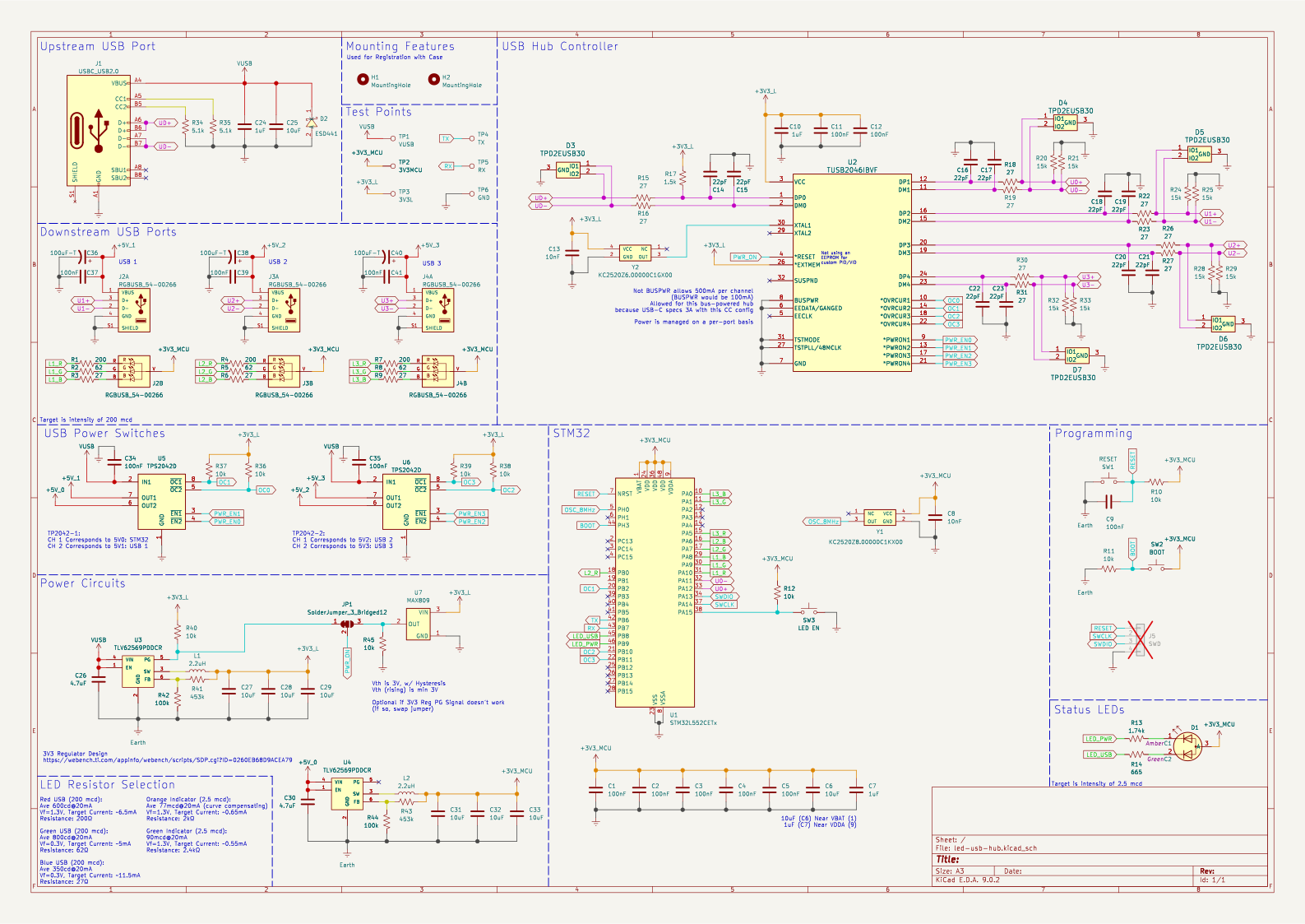
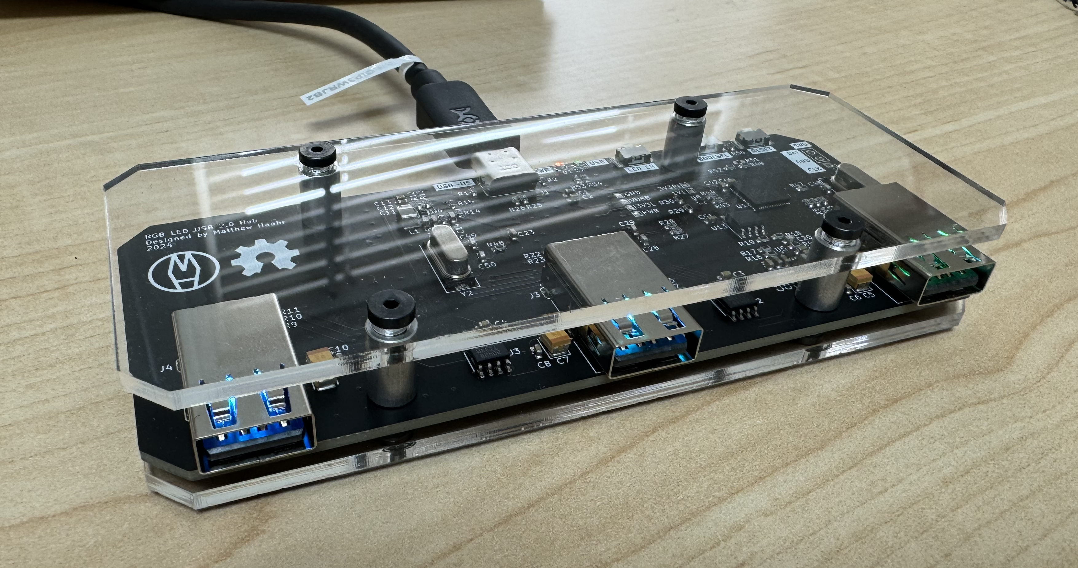
A 3 Port USB Hub, USB-C Upstream, USB A with RGB LED downstream, features an RP2040 to run the LEDs and possibly other features
LED USB Hub is an open-source printed circuit board by mjhaahr, from the mjhaahr/LED-USB-Hub repository on GitHub. It is a 4-layer board of 58.4 × 38.7 mm with 125 parts on 103 nets, routed with 1,115 tracks and 87 vias.
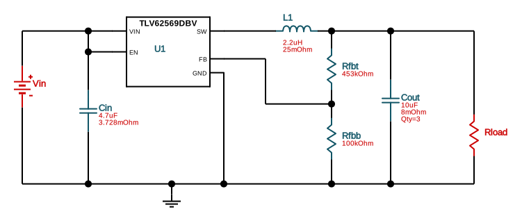
It is built around the TLV62569PDDCR, TUSB2046IBVF and TPS2042D, with the MAX809S, TPD2EUSB30DRT and KC2520Z8.00000C1KX00 among its other parts. Its parts include 45 resistors, 41 capacitors, 7 ICs, 7 diodes and 5 connectors. It belongs with the lEDs and displays and interfaces and adapters boards and the RP2040 and STM32 boards of this library.


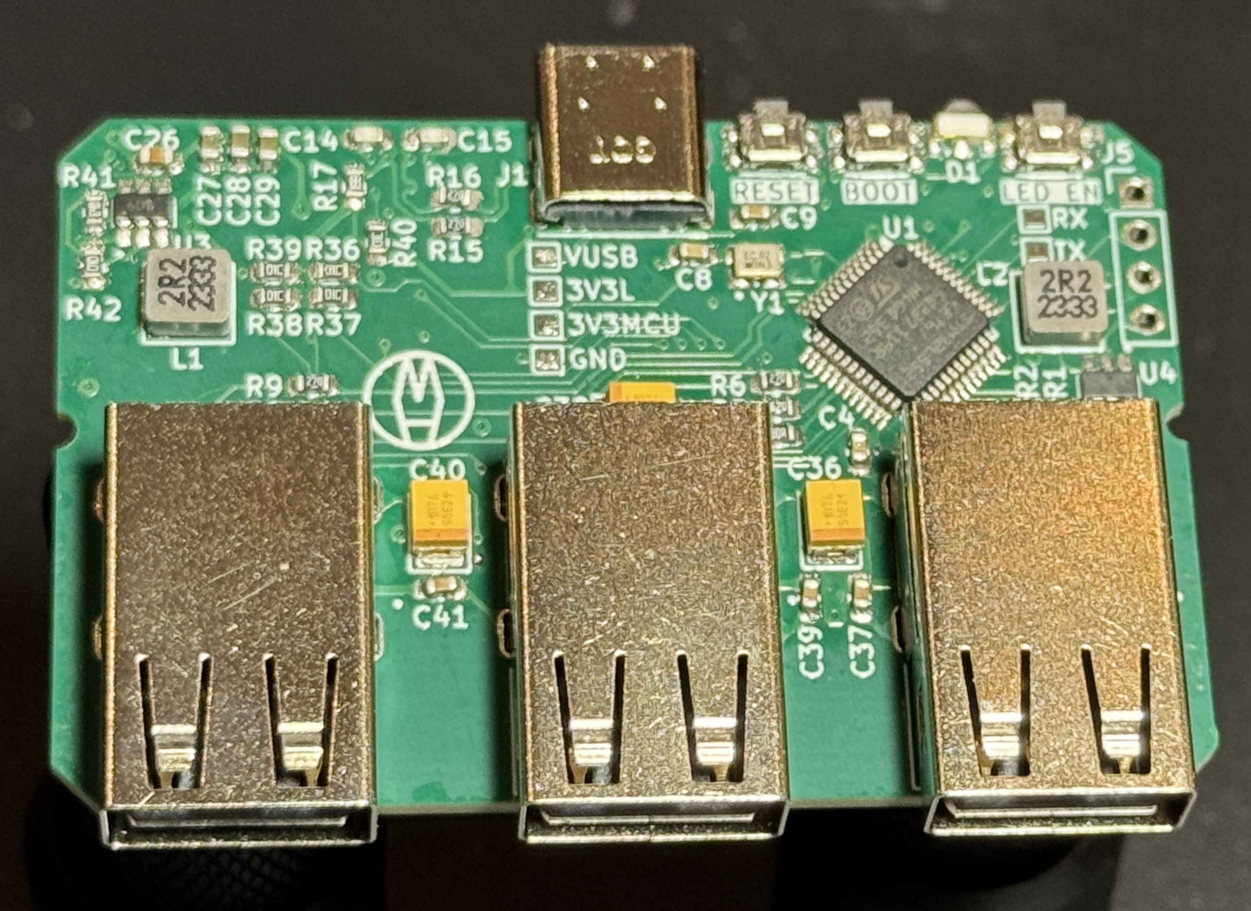
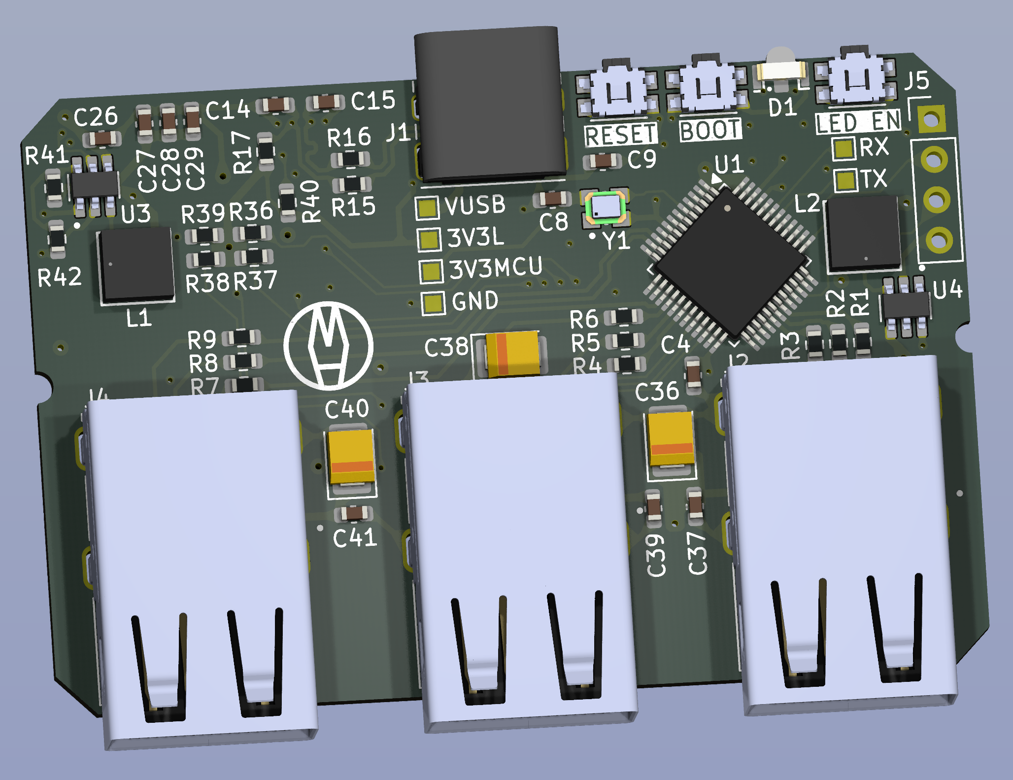
Version 3 of the RGB LED USB Hub was kindly supported by PCBWay, who graciously provided the PCBs for this project.
PCBWay offers very affordable and high-quality PCB manufacturing and assembly, as well as CNC machining and 3D printing, for hobbyists, low-volume prototyping, and even commercial use. They provide fast turnaround times, an easy-to-use service, and highly accurate and detailed boards all at a low cost. Their Standard PCBs satisfy most needs for reliable circuit boards: offering precise boards, layer counts up to 14, a wide variety of soldermask and silkscreen colors - even full color printing, and different materials like aluminum. But they also offer Advanced PCBs for even greater capabilities and performance or Flexible/Rigid-Flex PCBs when the designs need to bend.

| Qty | Value | Footprint | References |
|---|---|---|---|
| 13 | 100nF | Capacitor_SMD:C_0603_1608Metric | C1, C2, C3, C4, C5, C9, C11, C12, C34, C35, C37, C39, C41 |
| 13 | 27 | Resistor_SMD:R_0603_1608Metric | R3, R6, R9, R15, R16, R18, R19, R22, R23, R26, R27, R30, R31 |
| 10 | 22pF | Capacitor_SMD:C_0603_1608Metric | C14, C15, C16, C17, C18, C19, C20, C21, C22, C23 |
| 9 | 10k | Resistor_SMD:R_0603_1608Metric | R10, R11, R12, R36, R37, R38, R39, R40, R45 |
| 8 | 10uF | Capacitor_SMD:C_0603_1608Metric | C6, C25, C27, C28, C29, C31, C32, C33 |
| 8 | 15k | Resistor_SMD:R_0603_1608Metric | R20, R21, R24, R25, R28, R29, R32, R33 |
| 5 | TPD2EUSB30 | TPD2EUSB30DRTR:DRT0003A | D3, D4, D5, D6, D7 |
| 4 | LOGO | LOGO | G***, G1, G2, G3 |
| 3 | 100uF-T | Capacitor_Tantalum_SMD:CP_EIA-3528-15_AVX-H | C36, C38, C40 |
| 3 | 1uF | Capacitor_SMD:C_0603_1608Metric | C7, C10, C24 |
| 3 | 200 | Resistor_SMD:R_0603_1608Metric | R1, R4, R7 |
| 3 | 62 | Resistor_SMD:R_0603_1608Metric | R2, R5, R8 |
| 3 | RGBUSB_54-00266 | 54-00266 RGB-USB Port:RGBUSB_54-00266 | J2, J3, J4 |
| 2 | 100k | Resistor_SMD:R_0603_1608Metric | R42, R44 |
| 2 | 10nF | Capacitor_SMD:C_0603_1608Metric | C8, C13 |
| 2 | 2.2uH | SRP4020FA_2R2M:IND_SRP4020FA-2R2M_BRN | L1, L2 |
| 2 | 4.7uF | Capacitor_SMD:C_0603_1608Metric | C26, C30 |
| 2 | 453k | Resistor_SMD:R_0603_1608Metric | R41, R43 |
| 2 | 5.1k | Resistor_SMD:R_0603_1608Metric | R34, R35 |
| 2 | MountingHole | MountingHole:MountingHole_2mm | H1, H2 |
| 2 | TLV62569PDDCR | TLV62569PDDCR:SOT95P280X110-6N | U3, U4 |
| 2 | TPS2042D | Package_SO:SOIC-8_3.9x4.9mm_P1.27mm | U5, U6 |
| 1 | 1.5k | Resistor_SMD:R_0603_1608Metric | R17 |
| 1 | 1.74k | Resistor_SMD:R_0603_1608Metric | R13 |
| 1 | 3V3L | TestPoint:TestPoint_Pad_1.0x1.0mm_Mod | TP3 |
| 1 | 3V3MCU | TestPoint:TestPoint_Pad_1.0x1.0mm_Mod | TP2 |
| 1 | 665 | Resistor_SMD:R_0603_1608Metric | R14 |
| 1 | BOOT | EVQ_P7L01P:SW_EVQ-P7L01P | SW2 |
| 1 | ESD441 | EasyEDA2KiCad:X2SON-2_L0.6-W0.3-P0.35_ESD441DPLR | D2 |
| 1 | GND | TestPoint:TestPoint_Pad_1.0x1.0mm_Mod | TP6 |
| 1 | KC2520Z6.00000C1GX00 | KC2520Z6.00000C1GX00:OSC_KC2520Z6.00000C1GX00 | Y2 |
| 1 | KC2520Z8.00000C1KX00 | KC2520Z8_00000C1KX00:OSC_KC2520Z8.00000C1KX00 | Y1 |
| 1 | LED EN | EVQ_P7L01P:SW_EVQ-P7L01P | SW3 |
| 1 | MAX809 | Package_TO_SOT_SMD:SOT-23 | U7 |
| 1 | RESET | EVQ_P7L01P:SW_EVQ-P7L01P | SW1 |
| 1 | RX | TestPoint:TestPoint_Pad_1.0x1.0mm_Mod | TP5 |
| 1 | STM32L552CETx | Package_QFP:LQFP-48_7x7mm_P0.5mm | U1 |
| 1 | SWD | Connector_PinHeader_2.54mm:PinHeader_1x04_P2.54mm_Vertical | J5 |
| 1 | SolderJumper_3_Bridged12 | Jumper:SolderJumper-3_P1.3mm_Bridged12_RoundedPad1.0x1.5mm | JP1 |
| 1 | TUSB2046IBVF | Package_QFP:LQFP-32_7x7mm_P0.8mm | U2 |
| 1 | TX | TestPoint:TestPoint_Pad_1.0x1.0mm_Mod | TP4 |
| 1 | USBC_USB2.0 | Connector_USB:USB_C_Receptacle_GCT_USB4085 | J1 |
| 1 | VUSB | TestPoint:TestPoint_Pad_1.0x1.0mm_Mod | TP1 |
| 1 | ~ | HSMF-C143:HSMF-C143 | D1 |


protolux-electronics/trellis_core
A barebones KiCad project for Allwinner T113-based designs


R-Mutura/AD_POWER_DEVICE
Highly integrated Single board Computer with RK3566


It measures 58.4 × 38.7 mm and has 4 copper layers, 1.63 mm thick.
125 parts, built around the TLV62569PDDCR, TUSB2046IBVF, TPS2042D and MAX809S. The full list of its parts is on this page, with links to each part's symbol and footprint where PCBKit's library has them.
From the mjhaahr/LED-USB-Hub repository on GitHub, at the commit this page was made from: the board is led-usb-hub/led-usb-hub.kicad_pcb and its schematic led-usb-hub/led-usb-hub.kicad_sch. PCBKit opens the board in the browser, with nothing to install.
Its repository states no licence, so its author keeps all rights: ask mjhaahr before reusing the design.