


2 layers75.2 × 75.2 mm
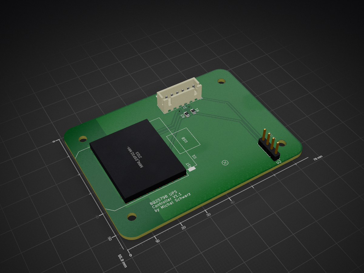
 misch2/ups12v6
12V UPS
Controller is an open-source printed circuit board by misch2, from the misch2/ups12v repository on GitHub, published under the MIT licence. It is a 2-layer board of 76 × 55.9 mm with 15 parts on 40 nets, routed with 30 tracks and 9 vias.
Its parts include 2 resistors, 2 ICs and 1 connector. It belongs with the power boards and the ESP32 boards of this library.
A hobby project to create simple 12 V UPS to backup my router and mini PC. Both appliances use 12 volts on input. This UPS:
Deployed to production, used for a backup of my Archer C6 router only. But it's mostly a proof of concept, with power limitations and without a proper PCB (components are just wired up together).
Schema: schema_v1.pdf
Some photos: photo1, photo2, photo3.
"boosterEnable" input is there not to save power but to prevent running the XL6009 booster in an undervoltage condition. This could have been implemented using a voltage comparator (LM311?) + schmitt trigger for hysteresis. I used software solution because tbne undervoltage condition doesn't occur "suddenly" but it's only a startup condition. And using software to control it allows me to use it for powering off the UPS when it runs on battery.
Replaced AMS1117 with a buck converter due to a large voltage difference and therefore large heat dissipation with LDO.
Added XL6009 "EN" pin control (initial pull down + software control from ESP32).
Used Schottky diodes.
Added a diode between battery power line and XL6009 to prevent backpropagation of voltage when XL6009 is powered down.
The limitations were caused by:
Anyway, this works well for the router. It can run for more than 2 hours from batteries because the router consumes only about 3 watts and the output current is therefore mostly below 300 mA. So I might call this a success ✅!
I wanted to overcome the limitations of the first version and to make it handle larger current to power the mini PC which might need up to 3 A. This higher current would also require something better than the INA219.
I also added relays to allow the UPS to be powered off completely when running on batteries. This is to allow the mini PC to power on automatically after a power outage. And a 2nd relay allows to power cycle the UPS or to run calibration.
ACS712 sensors paired with an ADS1115 ADC are used for current and voltage monitoring. It can handle up to 20 A.
A pair of XL74610 ideal diodes is used instead of Schottky diodes in v1, to achieve a lower voltage drop and to allow for higher currents.
TP5100 charger module is used for charging the batteries, combined with BMS for 2S 8.4V/20A.
Alas, while everything looked good on the paper, reality was different ❌. The "better" booster module (LM2587 version) advertises up to 5A and 30W, but something might be wrong with it. I'm not able to pull more than 1 A from the UPS, the voltage drastically drops if I try to pull more.
Possible causes (investigating ⌛):
An idea: disconnect the LM2587 booster and attach an electronic load to the battery instead of it. Then try to pull whatever it takes to see if the batteries can provide the current. If they can, then the problem is with the booster. If they can't, then the problem is with the batteries or BMS.
Result: ⌛
Maybe this was a completely bad approach. Sticking to 2x 18650 doesn't make sense if I need to pull 3 A. I should have used 4S 18650 (13.6 V - 16.8 V) and eliminate the boost converter completely. When stepping down to 12 V, the current would be lower and the voltage drop would be lower. Also no need to stick with 12 V and a boost converter on input.
Using BQ25798 battery charger IC from Texas Instruments. According to the datasheet it can handle up to 5 A on the output and 3A on the input and has a built-in buck-boost converter usable for either battery charging or for the UPS backup mode. It can also be controlled and monitored extensively using I2C.
Product info: https://www.ti.com/product/BQ25798
Most important features:
It's essentially a battery charger capable of using boost converter to charge the batteries, but it can also detect a drop in input voltage and switch to the backup mode aka battery mode very fast. In the backup mode it works as buck converter and uses the batteries to power the load.
So, theoretically, with this IC I can eliminate all the former external circuitry because BQ25798 will take care of both charging the batteries and providing power to the load. And it has hundreds of I2C registers to set up and monitor the system.
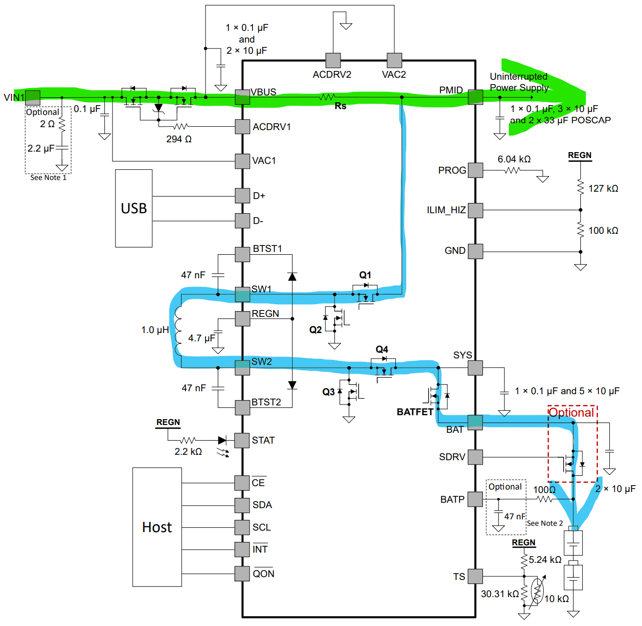
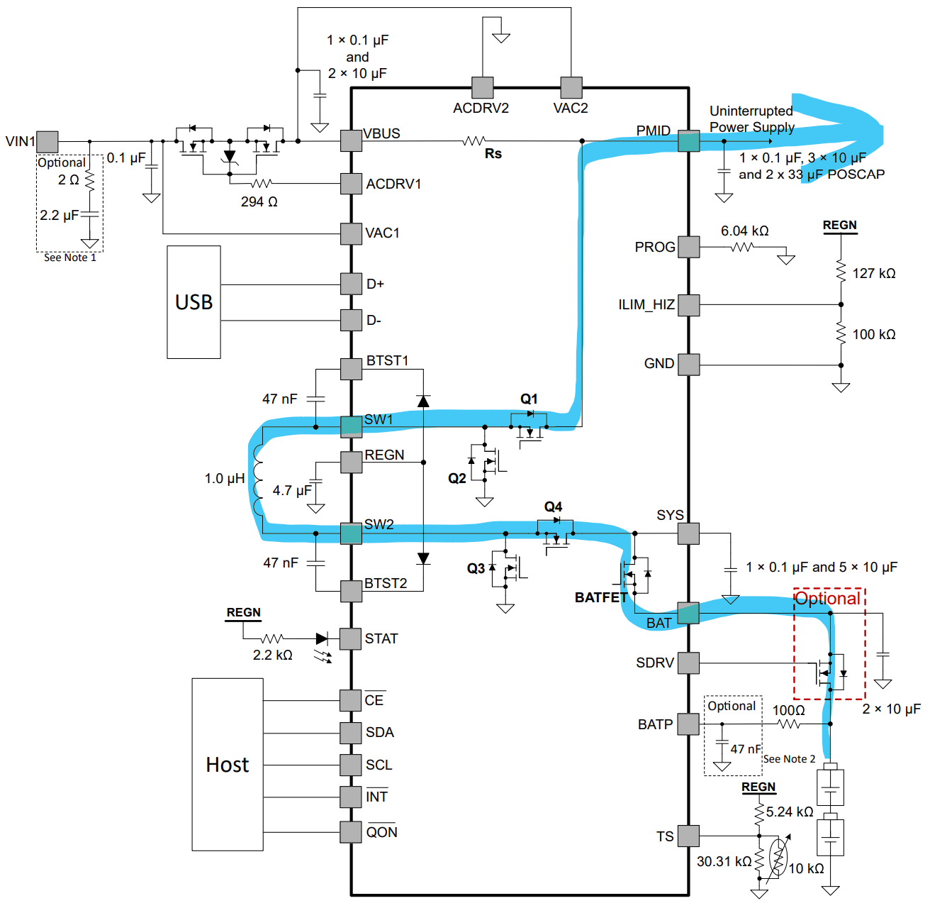
See page 133 of datasheet:
L = 2.2 µH (only two inductor values are available: 2.2 µH and 1 µH)

Isat >= MAX((Iin + Iripple/2), Ichg + Iripple/2)

Iripple_buck = Vsys / Vbus * (Vbus - Vsys) / (Fsw * L)
Iripple_boost = Vbus /Vsys * (Vsys - Vbus) / (Fsw * L)
For my purposes (12 V input, 12 V output, 4S Li-Ion battery pack, 3 A power source) the values are:
Iin = 3 A (input current)
Vbus = 12 V (input voltage)
Vsys = +16.8 V (battery voltage)

Iripple_buck = 12 V / 16.8 V * (16.8 V - 12 V) / (750 kHz * 2.2 uH) = 3.43 / 1.65 = 2.08 A
Iripple_boost = 16.8 V / 12 V * (12 V - 16.8 V) / (750 kHz * 2.2 uH) = -6.72 / 1.65 = -4.07 A

Isat >= MAX(5.08 A, 7.07 A) = 7.07 ASee page 25 of datasheet:
2.2 uH inductor requires 750 kHz switching frequency. Therefore the PROG resistor = 27 kOhm which means:
In this mode PMID follows VBUS, i.e. it's not regulated. PMID is also the input to the buck-boost converter.
The FETs between AC1 and VBUS provide reverse blocking (prevents battery voltage from being seen at VBUS). PMID is output of the buck/boost converter.
| Qty | Value | Footprint | References |
|---|---|---|---|
| 4 | MountingHole | MountingHole:MountingHole_3.2mm_M3 | H1, H2, H3, H4 |
| 2 | 2k2 | Resistor_SMD:R_0805_2012Metric | R1, R2 |
| 1 | G*** | kibuzzard-6810F0CD | kibuzzard-6810F0CD |
| 1 | G*** | kibuzzard-6810EFE9 | kibuzzard-6810EFE9 |
| 1 | G*** | kibuzzard-683D9CD5 | kibuzzard-683D9CD5 |
| 1 | G*** | kibuzzard-6810F0D5 | kibuzzard-6810F0D5 |
| 1 | G*** | kibuzzard-6810F0BF | kibuzzard-6810F0BF |
| 1 | G*** | kibuzzard-6810F062 | kibuzzard-6810F062 |
| 1 | I2C etc. | Connector_JST:JST_XH_B6B-XH-A_1x06_P2.50mm_Vertical | J1 |
| 1 | Micro step down converter | Modules_MCU:Micro stepdown converter | U2 |
| 1 | mini_esp32 MH-ET-Live | Modules_MCU:ESP32_mini MH-ET-LIVE | U1 |
It measures 76 × 55.9 mm and has 2 copper layers, 1.6 mm thick.
15 parts. The full list of its parts is on this page, with links to each part's symbol and footprint where PCBKit's library has them.
From the misch2/ups12v repository on GitHub, at the commit this page was made from: the board is hardware/v2-3/controller/controller.kicad_pcb and its schematic hardware/v2-3/bq25798_breakout_board/Controller.kicad_sch. PCBKit opens the board in the browser, with nothing to install.
Its repository publishes it under the MIT licence: you may reuse it on that licence's terms (keep the author's notice, and for a copyleft licence share your changes alike).


google/mozc-devices
Circuit diagrams and firmware source code for Gboard DIY keyboards

hoglet67/RGBtoHDMI
Bare-metal Raspberry Pi project that provides pixel-perfect sampling of Retro Computer RGB/YUV video and conversion to HDMI

mntmn/amiga2000-gfxcard
MNT VA2000, an Open Source Amiga 2/3/4000 Graphics Card (Zorro II/III), written in Verilog

hackclub/OnBoard
💡 Join 1,000 teenagers and make your first PCB with a $100 grant!

kenp-io/not-for-airpods-repairs
The content of this repository is licensed under the WTFPL License. Please have a close look at the terms before using this material.

Luos-io/luos_engine
Open-source and real-time orchestrator for cyber-physical-systems, to easily design, test and deploy embedded applications and digital twins.

Chrismettal/EleLab_v2
Cheap DIY lab system for hobbyists and the tinkering folk
