

4 layers104.3 × 106.8 mm
Sk162-herd mixer
mirdej/synkie
The Synkie is a modular open source analog video processor, developed by Michael Egger, Max Egger and Flo Kaufmann
223 parts47

 mirdej/synkie47
The Synkie is a modular open source analog video processor, developed by Michael Egger, Max Egger and Flo Kaufmann
Inputs Trigger Dual Compa is an open-source printed circuit board by mirdej, from the mirdej/synkie repository on GitHub. It is a 2-layer board with 19 parts on 12 nets, routed with 87 tracks and 3 vias.
It is built around the LM393 and BAT54S. Its parts include 10 resistors, 2 capacitors, 2 diodes, 2 connectors and 1 IC.
The Synkie is a modular open source analog video processor, developed by Michael Egger, Max Egger and Flo Kaufmann. A bit like the venerable modular Moog synthesizer it lets you toy around with the signal using patch cables – but this time not producing sound but images. It is an instrument for video, a playground, a platform to explore new ways to transform a video signal. Synkie is still in development, we constantly develop new modules – and even the base specifications may still change over time.
Synkie’s main goal is playability not image quality, even though we try to design each module as best as we can. But patching is done with 2mm laboratory cables – not shielded 75Ohm BNC cables as one would normally use for video. No, you can even use any blank wire and tinker around with the signal in real time on the sk90-breadboard module… The laboratory plugs can be stacked, so you can easily divide the signal into multiple paths, feeding multiple modules at once and change the configuration on the fly. The resulting image can get quite messy down the road, but that’s part of the fun, or maybe even the main purpose…
This Github repository is our working space and not a DIY tutorial. Lots of stuff is completely outdated and/or poorly documented. Here are some important notes about the current state of things (Oct 2021):
Pretty much everything in the EAGLE directory is totally obsolete and we only keep it for documentation.
We settled on the LMH6643 as our Opamp of choice for almost everything where frequency response matters. Not all schematics reflect this. In most cases if there's an opamp named "generic opamp" or even "LM833" - we probably meant LMH6643.
There are several modules where the supply connector is flipped. As we etch a lot of boards ourselves there is no silkscreen and we don't see the error. ALWAYS check the polarity !
We live in PAL land. These modules have not beent tested with NTSC video. Some might need to be adapted slightly, some might even work better than here ;-)
If you have any questions contact info@synkie.net
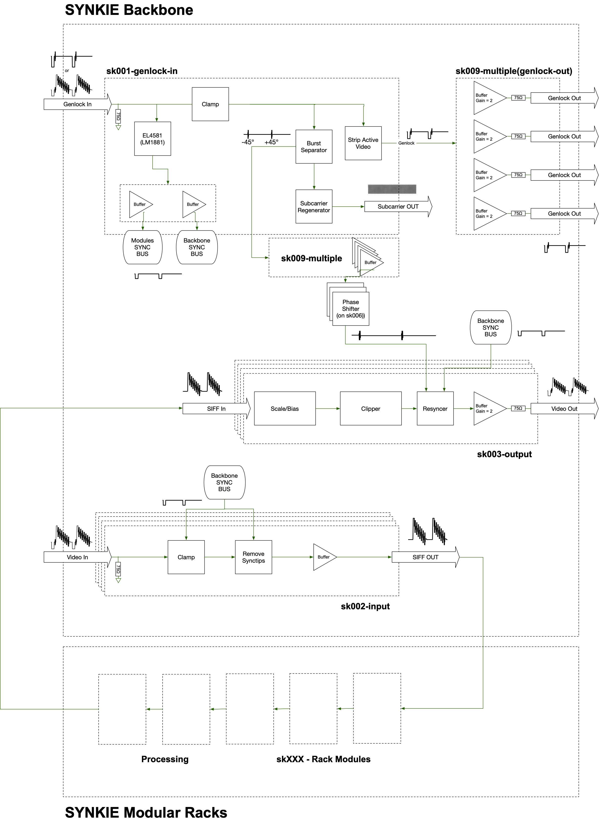
Modules sk000 to sk009 constitute the Synkie Backbone – handling Ins out Outs to the normal Video World. Input video is clamped (black level = GND) and stripped of timing signals and color burst. This signal can then be fed to any processing modules. In the end , timing signals and a phase corrected color burst is cut back into the modified signal, in sync with the Genlock input.
Power distribution to backbone modules and rack. +5V, GND, -5V.
This module takes any standard video signal as input and generates all necessary timing signals for the Synkie system. The input is first backporch-clamped to GND and all active video is cut off. This black image can serve as a genlock for connected sources (cameras). Colorburst is output as a seperate signal and used to syncronise a quartz crystal that generates a continuous 4.4336Mhz subcarrier signal for the rgb modules. A LM1881 generates the digital sync signals: horizontal sync, vertical sync, backporch and odd/even.
This modules takes any standard video signal, clamps black level to GND and strips off synctips and colorburst. (still in active debate: me thinks sk002 should apply a gain of 1.43 to bring the 0.7V white level up to 1V)
This module takes any signal as its input (from DC to 10Mhz). The scale-bias section controls amplitude and dc-shift. The signal is then clipped hard between 0V and 1V. Finally the resyncer adds synctips and colorburst to make it look like a standard video signal. When using video as an input to the sk003 any processing beforehand can add some tiny delay - depending on how many modules the signal passes through - which causes a phase shift in the signal that can alter or completely destroy color. That is why the burst signal from sk001 first goes through a sk004-burstshift (allpass filter) that lets correct the phase error before it gets cut back into the video signal.
| Signal name | Waveform | Description | Specs |
|---|---|---|---|
| Genlock |  | A video signal that serves as the master synchronisation signal. Can be routed through and used as an input. | -0.3V to 0.7V |
| Video | 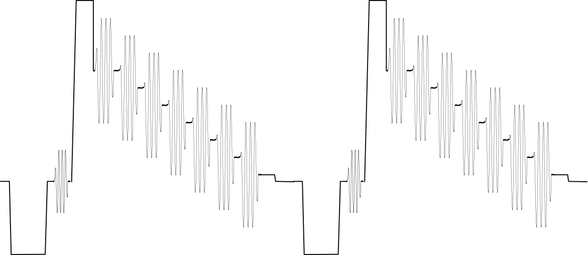 | Standard PAL video signal | -0.3V to 0.7V |
| Sync |  | Digital sync pulses: H-Sync, V-Sync, Backporch, Odd/Even | 0V to 5V |
| Burst |  | Colorburst only, AC coupled | ca. -0.1V to 0.1V |
| Siff | 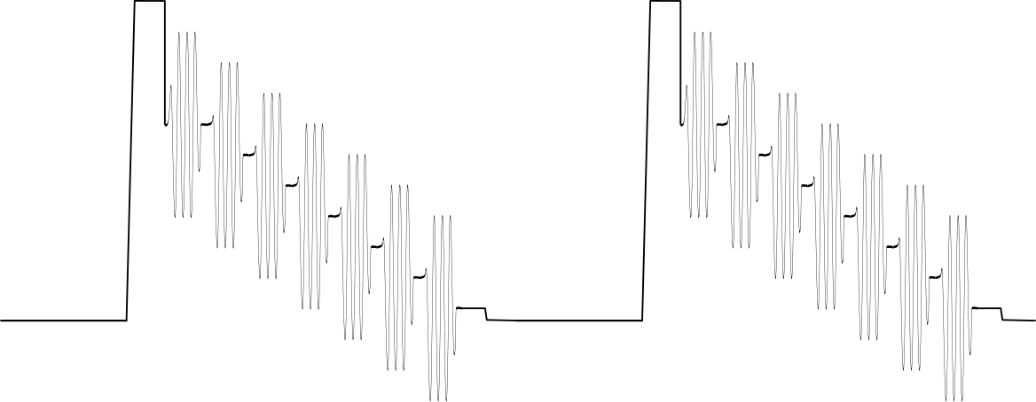 | Synkie signal. Can be anything, DC, CV, Audio or Video. 0V means black. 1V means white | -1V to 1V |
Synkie's goal is to be able to mix all signals, be it control signals, audio or picture. You should be able to use a video image as control voltage for a VCO like you should be able to inject a sound into the video or watch a steady 0.256 volts.
This has the following implications for synkie modules:
| Qty | Value | Footprint | References |
|---|---|---|---|
| 4 | 47k | Resistor_SMD:R_0603_1608Metric | R7, R8, R10, R15 |
| 4 | 75 | Resistor_SMD:R_0603_1608Metric | R5, R9, R13, R14 |
| 2 | 4k7 | Resistor_SMD:R_0603_1608Metric | R6, R16 |
| 2 | BAT54S | Package_TO_SOT_SMD:SOT-23 | D1, D2 |
| 1 | 100n | Capacitor_SMD:C_0603_1608Metric | C7 |
| 1 | C-Trig | Capacitor_SMD:C_0805_2012Metric | C1 |
| 1 | Comp1Out | TestPoint:TestPoint_Pad_D1.0mm | TP3 |
| 1 | Comp2Out | TestPoint:TestPoint_Pad_D1.0mm | TP4 |
| 1 | Gate In | synkie_frontplate_footprints:Banana2mm-Löthülse | J1 |
| 1 | LM393 | Package_SO:SOIC-8_3.9x4.9mm_P1.27mm | U1 |
| 1 | Trigger In | synkie_frontplate_footprints:Banana2mm-Löthülse | J2 |
mirdej/synkie
The Synkie is a modular open source analog video processor, developed by Michael Egger, Max Egger and Flo Kaufmann

mirdej/synkie
The Synkie is a modular open source analog video processor, developed by Michael Egger, Max Egger and Flo Kaufmann

mirdej/synkie
The Synkie is a modular open source analog video processor, developed by Michael Egger, Max Egger and Flo Kaufmann

mirdej/synkie
The Synkie is a modular open source analog video processor, developed by Michael Egger, Max Egger and Flo Kaufmann

mirdej/synkie
The Synkie is a modular open source analog video processor, developed by Michael Egger, Max Egger and Flo Kaufmann

mirdej/synkie
The Synkie is a modular open source analog video processor, developed by Michael Egger, Max Egger and Flo Kaufmann

mirdej/synkie
The Synkie is a modular open source analog video processor, developed by Michael Egger, Max Egger and Flo Kaufmann

mirdej/synkie
The Synkie is a modular open source analog video processor, developed by Michael Egger, Max Egger and Flo Kaufmann

mirdej/synkie
The Synkie is a modular open source analog video processor, developed by Michael Egger, Max Egger and Flo Kaufmann

mirdej/synkie
The Synkie is a modular open source analog video processor, developed by Michael Egger, Max Egger and Flo Kaufmann

mirdej/synkie
The Synkie is a modular open source analog video processor, developed by Michael Egger, Max Egger and Flo Kaufmann

mirdej/synkie
The Synkie is a modular open source analog video processor, developed by Michael Egger, Max Egger and Flo Kaufmann

mariusgreuel/EMS-Bus-Gateway
EMS Bus Gateway for Buderus Boilers to run EMS-ESP32


schlae/snark-barker-mca
A Sound Blaster compatible sound card for Micro Channel bus computers

michaelruppe/FSAE
Projects for Formula SAE Electric Vehicle competition (Australia 2019/2020)
19 parts, built around the LM393 and BAT54S. The full list of its parts is on this page, with links to each part's symbol and footprint where PCBKit's library has them.
From the mirdej/synkie repository on GitHub, at the commit this page was made from: the board is kicad/SynkieDesignBlocks.kicad_blocks/Inputs_Trigger_Dual_Compa.kicad_block/Inputs_Trigger_Dual_Compa.kicad_pcb. PCBKit opens the board in the browser, with nothing to install.
Its repository states no licence, so its author keeps all rights: ask mirdej before reusing the design.