2 layers35 × 25 mm
Accelerometer subboard
Miqeo/Vibration_sensor_node
Self contained accelerometer and gyroscope sensor accessible wirelessly and able to capture the data.
15 partsCC0-1.0
 Miqeo/Vibration_sensor_node
Self contained accelerometer and gyroscope sensor accessible wirelessly and able to capture the data.
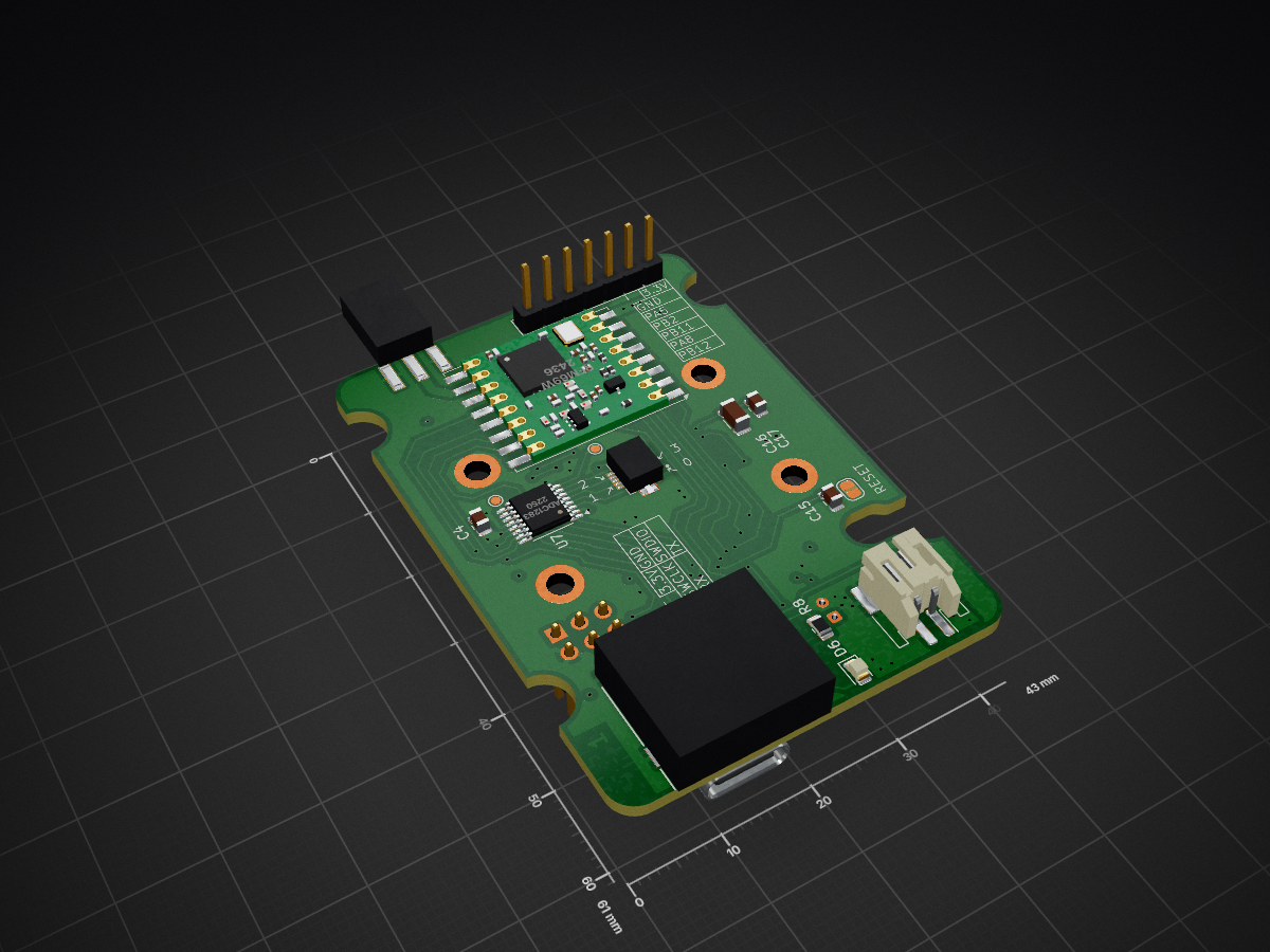
Accelerometer controller is an open-source printed circuit board by Miqeo, from the Miqeo/Vibration_sensor_node repository on GitHub, published under the CC0-1.0 licence. It is a 4-layer board of 43 × 61 mm with 63 parts on 90 nets, routed with 603 tracks and 90 vias.
It is built around the ADC1283IPT, S25FL128SAGNFV001 and AMS1117, with the MPU-6050 among its other parts. Its parts include 22 capacitors, 11 resistors, 8 connectors, 7 ICs and 4 diodes. It belongs with the sensors and measurement boards and the STM32 boards of this library.


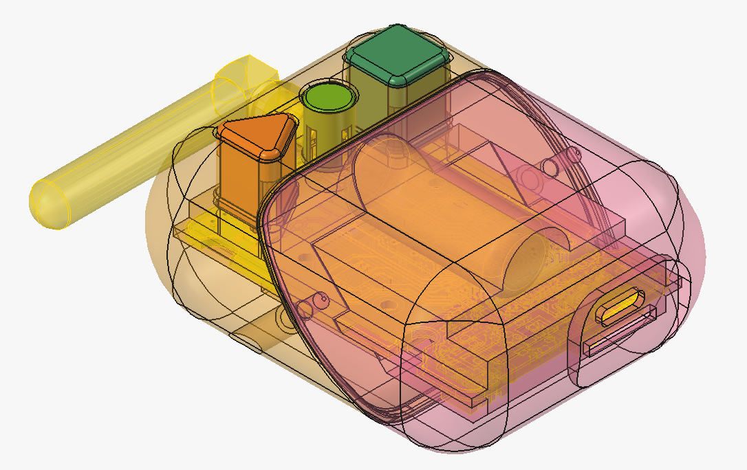
Since my first endeavour into PCB and CAD design, I have always wanted to create something from start to finish. This was possible with one of the previous projects I was a part of, where there was a need to make a Raspberry Pi HAT, the software to run with it, and the corresponding casing.
As that project came to a close, I wanted to make use of my time and extend my knowledge with this initiative to make something useful and to test the capabilities of FOSS software such as Freecad and Kicad.
This culminated in the amalgamation of sensors, storage, comms, and compute that can be called a “node” for the distributed sensor system.
As this is a work in progress, and the exact use might change with time, I do not want to point towards the problem it might, in the future, solve. The time-synchronised system of this kind may be used in places where other, physically connected or remote nodes are used now.
The planned capabilities of the node are to autonomously save vibration data and synchronize it in time with other nodes using a wireless link. The nodes equipped with the 3-axis gyroscope would also be able to track changes in rotation.
The system makes use of the small cyllindrical battery, repurposed from an ellectrical cigarette. The main computation is done by the STM32 microcontroller, which has access to the onboard accrellerometer-gyroscope combo and an extensible accelerometer via a board-to-board connector. The microcontroller is connected to the outside world via the wireless module and usb 2.0 via USB-C, which also acts as the charger for the unit. The data collected can be stored on the external SD card or the soldered-on QSPI flash.
Here is the schematic document of the controller board
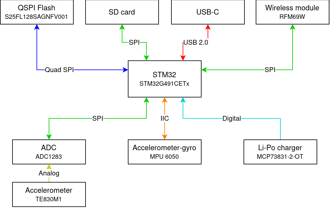
Data flow of the system
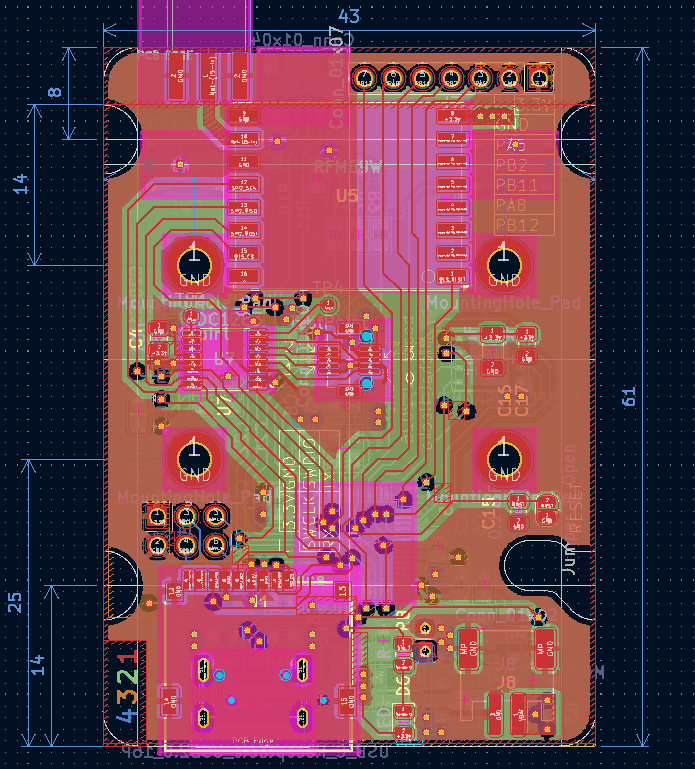
The main controller PCB
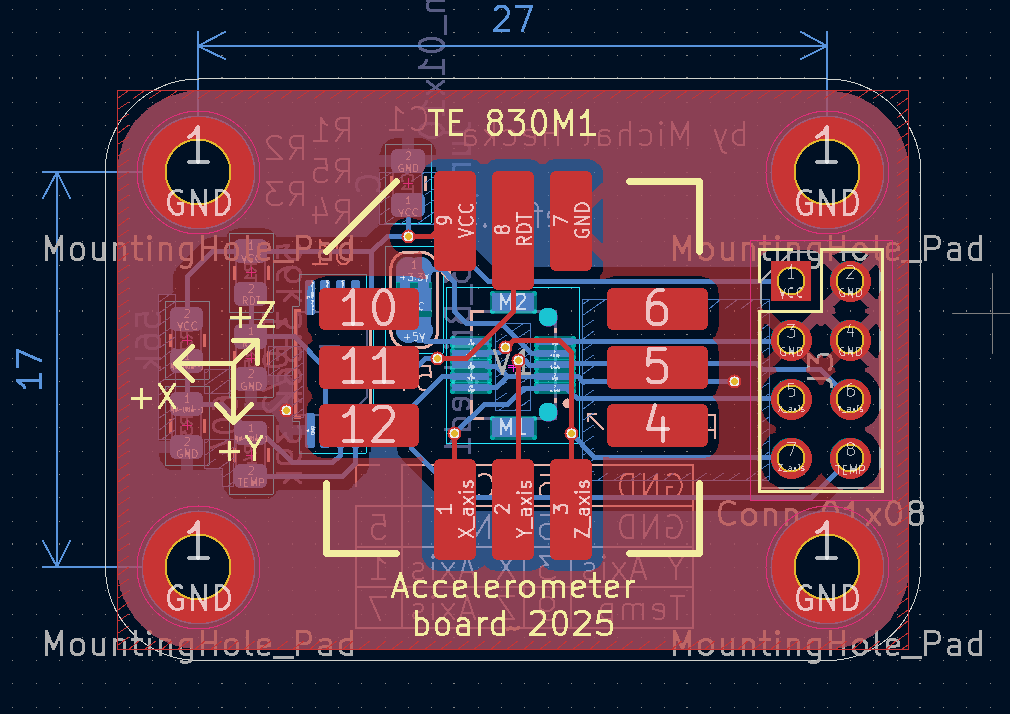
A sensor sub-board connected via a board-to-board connector
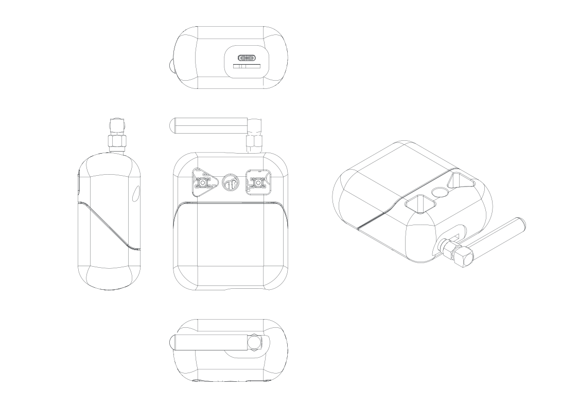
Model of the the sensor casing
| Qty | Value | Footprint | References |
|---|---|---|---|
| 5 | R | Resistor_SMD:R_0805_2012Metric | R1, R2, R7, R8, R9 |
| 4 | 1 uF | Capacitor_SMD:C_0805_2012Metric | C6, C10, C11, C17 |
| 4 | 10k | Resistor_SMD:R_0805_2012Metric | R3, R4, R10, R11 |
| 4 | 10n | Capacitor_SMD:C_0805_2012Metric | C4, C18, C19, C21 |
| 4 | 5 pF | Capacitor_SMD:C_0805_2012Metric | C7, C8, C13, C14 |
| 4 | MountingHole_Pad | MountingHole:MountingHole_2.7mm_M2.5_DIN965_Pad | H1, H2, H3, H4 |
| 2 | 10 uF | Capacitor_SMD:C_1206_3216Metric | C12, C16 |
| 2 | 100 nF | Capacitor_SMD:C_0805_2012Metric | C2, C3 |
| 2 | 5.1k | Resistor_SMD:R_0805_2012Metric | R5, R6 |
| 2 | D | Diode_SMD:D_SOD-123 | D1, D3 |
| 2 | SW_Push | Button_Switch_SMD:SW_Push_1P1T_XKB_TS-1187A | SW1, SW2 |
| 2 | TestPoint | TestPoint:TestPoint_Pad_D1.0mm | TP3, TP4 |
| 1 | 0.1 uF | Capacitor_SMD:C_0805_2012Metric | C15 |
| 1 | 0.1u | Capacitor_SMD:C_0805_2012Metric | C22 |
| 1 | 10 nF | Capacitor_SMD:C_0805_2012Metric | C5 |
| 1 | 10 uF | Capacitor_THT:CP_Radial_D4.0mm_P2.00mm | C9 |
| 1 | 2.2n | Capacitor_SMD:C_0805_2012Metric | C20 |
| 1 | 4.7 uF | Capacitor_SMD:C_0805_2012Metric | C1 |
| 1 | ADC1283 | Package_SO:TSSOP-16_4.4x5mm_P0.65mm | U7 |
| 1 | AMS1117 | Package_TO_SOT_SMD:SOT-89-3 | U2 |
| 1 | Conn_01x02 | Connector_JST:JST_PH_S2B-PH-SM4-TB_1x02-1MP_P2.00mm_Horizontal | J8 |
| 1 | Conn_01x04 | Connector_JST:JST_SH_SM04B-SRSS-TB_1x04-1MP_P1.00mm_Horizontal | J2 |
| 1 | Conn_01x06 | Connector_PinHeader_2.54mm:PinHeader_2x03_P2.54mm_Vertical | J4 |
| 1 | Conn_01x07 | Connector_PinHeader_2.54mm:PinHeader_1x07_P2.54mm_Vertical | J7 |
| 1 | Conn_01x10 | Private_library:AMPHENOL_10132797-011100LF | J3 |
| 1 | Conn_Coaxial | Private_library:ADAMTECH_RF2-143-T-17-50-G | J5 |
| 1 | Crystal_GND24 | Crystal:Crystal_SMD_3225-4Pin_3.2x2.5mm | Y3 |
| 1 | Jumper_2_Open | Jumper:SolderJumper-2_P1.3mm_Open_RoundedPad1.0x1.5mm | JP1 |
| 1 | LED | LED_SMD:LED_0805_2012Metric | D6 |
| 1 | LED_BAGR | Private_library:OSTB0805C1E-A-0.8T | D4 |
| 1 | MCP73831-2-OT | Package_TO_SOT_SMD:SOT-23-5 | U4 |
| 1 | MPU-6050 | Sensor_Motion:InvenSense_QFN-24_4x4mm_P0.5mm | U8 |
| 1 | RFM69W | RF_Module:HOPERF_RFM69HW | U5 |
| 1 | S25FL128SAGNFV001 | Package_SON:WSON-8-1EP_6x5mm_P1.27mm_EP3.4x4.3mm | U6 |
| 1 | SD_Card_Device | Private_library:112J-TDAR-R01_ATT | J1 |
| 1 | STM32G491CETx | Package_QFP:LQFP-48_7x7mm_P0.5mm | U1 |
| 1 | SolderJumper_3_Bridged12 | Jumper:SolderJumper-3_P1.3mm_Bridged12_RoundedPad1.0x1.5mm | JP2 |
| 1 | USB_C_Receptacle_USB2.0_16P | Connector_USB:USB_C_Receptacle_GCT_USB4105-xx-A_16P_TopMnt_Horizontal | J10 |
It measures 43 × 61 mm and has 4 copper layers, 1.6 mm thick.
63 parts, built around the ADC1283IPT, S25FL128SAGNFV001, AMS1117 and MPU-6050. The full list of its parts is on this page, with links to each part's symbol and footprint where PCBKit's library has them.
From the Miqeo/Vibration_sensor_node repository on GitHub, at the commit this page was made from: the board is pcb/accelerometer_controller/accelerometer_controller.kicad_pcb and its schematic pcb/accelerometer_controller/accelerometer_controller.kicad_sch. PCBKit opens the board in the browser, with nothing to install.
Its repository publishes it under the CC0-1.0 licence: you may reuse it on that licence's terms (keep the author's notice, and for a copyleft licence share your changes alike).
Miqeo/Vibration_sensor_node
Self contained accelerometer and gyroscope sensor accessible wirelessly and able to capture the data.


NBence0/JedlikBots
Welcome to the official GitHub page of JedlikBots! 🎓🤖 We are the dedicated team of software development and robotics students from the Jedlik Ányos Technical School in Győr, Hungary.


include-stdioH/TriVision-Smart-Driver-Monitoring-Board
ESP32-S3 based Smart Driver Monitoring Sensor Board designed in KiCad.

miura-bot/miura_bot-electrical
Electrical hardware development for autonomous origami inspired robot.

TanujRai14/Sat_pcb_design
This repository contains the PCB design files and documentation for a Can Satellite, featuring multiple environmental and orientation sensors, power management, and wireless communication capabilities.