2 layers40 × 20 mm
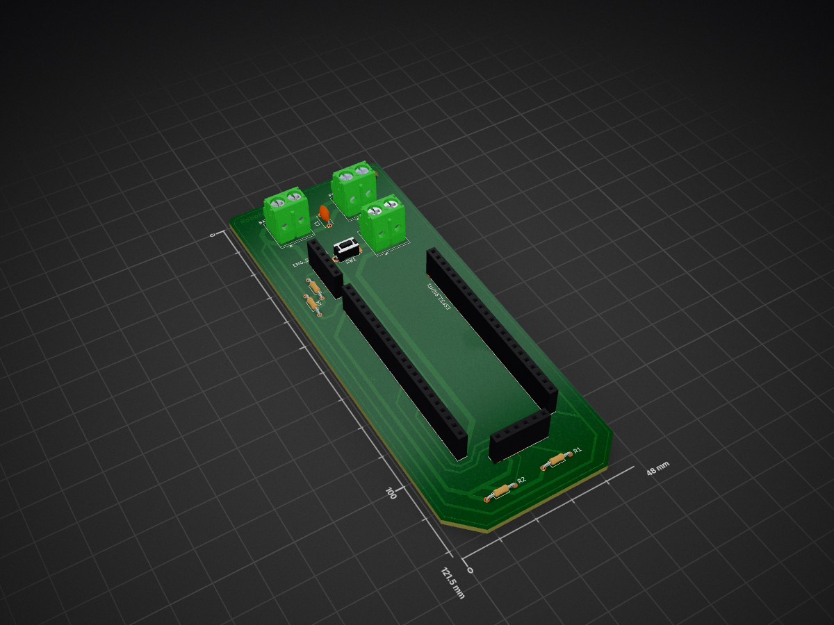
 Minecrapft/BionicHand3
our project in CEDD source code in bionic hand using esp32s3 micro controller
BionicHand is an open-source printed circuit board by Minecrapft, from the Minecrapft/BionicHand repository on GitHub. It is a 2-layer board of 48 × 121.5 mm with 13 parts on 47 nets, routed with 135 tracks and 0 vias.
Its parts include 4 resistors, 1 capacitor and 1 switch.
A simple Arduino sketch to control a robotic hand (servo-based) — provided as Robohand.ino.
This project contains an Arduino sketch that reads inputs (sensors/buttons/potentiometers) and drives servos to move a robotic hand. Use this README to set up the hardware, upload the sketch, and customize pin mappings or servo ranges.
Robohand.ino — main Arduino sketch (open in Arduino IDE).Adjust pin numbers in Robohand.ino to match your wiring.
Robohand.ino in the Arduino IDE.Tools → Board / Port.If using external servo power, ensure the external supply is connected and common-grounded with the Arduino before powering servos.
Robohand.ino and edit pin definitions and servo limits to match your hardware.If you want help customizing the sketch or wiring, open an issue or reply here.
This sketch can run on an ESP32-S3-based board with a few small changes. Follow these steps to connect and upload:
Tools → Board → Boards Manager and install the "esp32" package by Espressif.Robohand.ino uses the AVR Servo.h, switch to an ESP32-compatible servo library such as ESP32Servo (install via Library Manager) or use a PWM/i2c driver (PCA9685) for many servos.Robohand.ino to the GPIOs you wired.min/max values to avoid binding).Tools → Board → ESP32S3 Dev Module (or the specific board name) and the correct Port.These steps should get Robohand.ino running on an ESP32-S3 board. If you want, I can update Robohand.ino to include ESP32Servo examples and default ESP32 pin definitions.
To control the robot hand from your phone using a web browser on the local network:
Connect ESP32-S3 to WiFi:
Robohand.ino:
const char* ssid = "YOUR_WIFI_SSID";
const char* password = "YOUR_WIFI_PASSWORD";setup():
WiFi.begin(ssid, password);
while (WiFi.status() != WL_CONNECTED) {
  delay(500);
}
Serial.println(WiFi.localIP());192.168.1.100).Create a simple web server:
Robohand.ino:
#include <WiFi.h>
#include <WebServer.h>WebServer server(80); // Listen on port 80 (HTTP)setup(), define a handler that serves an HTML control panel:
server.on("/", HTTP_GET, []() {
  String html = "<html><body style='font-family:Arial'>"
    "<h1>Robohand Control</h1>"
    "<button onclick=\"fetch('/servo?pin=18&pos=90')\">Thumb Open</button>"
    "<button onclick=\"fetch('/servo?pin=18&pos=0')\">Thumb Close</button><br>"
    "<button onclick=\"fetch('/servo?pin=19&pos=90')\">Index Open</button>"
    "<button onclick=\"fetch('/servo?pin=19&pos=0')\">Index Close</button><br>"
    "</body></html>";
  server.send(200, "text/html", html);
});server.on("/servo", HTTP_GET, []() {
int pin = server.arg("pin").toInt();
int pos = server.arg("pos").toInt();
// Attach servo and move to position
// (details depend on your Servo library)
server.send(200, "text/plain", "OK");
});setup():
server.begin();loop(), handle incoming requests:
server.handleClient();Access from your phone:
RoboHand-S3 WiFi network (password: 12345678).http://192.168.4.1Customize the web interface:
<input type="range" min="0" max="180" value="90"
onchange="fetch('/servo?pin=18&pos=' + this.value)">/servo endpoint is correctly wired to your servo control code.| Qty | Value | Footprint | References |
|---|---|---|---|
| 3 | 10k | Resistor_THT:R_Axial_DIN0204_L3.6mm_D1.6mm_P7.62mm_Horizontal | R1, R2, R3 |
| 3 | Screw_Terminal_01x02 | TerminalBlock_MetzConnect:TerminalBlock_MetzConnect_Type073_RT02602HBLU_1x02_P5.08mm_Horizontal | BATTERY_INPUT1, BUCK_TB1, PCA9685_TB1 |
| 2 | Conn_01x06 | Connector_PinSocket_2.54mm:PinSocket_1x06_P2.54mm_Vertical | EMG_SENSOR1, PCA9685 |
| 2 | Conn_01x22 | Connector_PinSocket_2.54mm:PinSocket_1x22_P2.54mm_Vertical | ESP32_LEFT1, ESP32_RIGHT1 |
| 1 | 20k | Resistor_THT:R_Axial_DIN0204_L3.6mm_D1.6mm_P7.62mm_Horizontal | R4 |
| 1 | 470u | Capacitor_THT:C_Disc_D5.0mm_W2.5mm_P5.00mm | C1 |
| 1 | SW_DPST_x2 | Button_Switch_THT:SW_PUSH_1P1T_6x3.5mm_H4.3_APEM_MJTP1243 | SW1 |


samyk/magspoof
A portable device that can spoof/emulate any magnetic stripe, credit card or hotel card "wirelessly", even on standard magstripe (non-NFC/RFID) readers.

fossasia/pslab-scripts
Pocket Science Lab - Scripts for Sensor Experiments


willem-pennings/balancing-cube
A cube that balances itself in a corner or edge using reaction wheels

VoronDesign/Voron-Hardware
Cool Hardware designed by the Voron Design group

hoglet67/RGBtoHDMI
Bare-metal Raspberry Pi project that provides pixel-perfect sampling of Retro Computer RGB/YUV video and conversion to HDMI
It measures 48 × 121.5 mm and has 2 copper layers, 1.6 mm thick.
13 parts. The full list of its parts is on this page, with links to each part's symbol and footprint where PCBKit's library has them.
From the Minecrapft/BionicHand repository on GitHub, at the commit this page was made from: the board is all-project-files/bionic_hand_pcb/bionic_hand.kicad_pcb and its schematic all-project-files/bionic_hand_pcb/bionic_hand.kicad_sch. PCBKit opens the board in the browser, with nothing to install.
Its repository states no licence, so its author keeps all rights: ask Minecrapft before reusing the design.