
2 layers22.2 × 46.4 mm
C64-Switchless Quad Kernal Switcher
bwack/C64-Switchless-Multi-Kernal-27C256-adapter
Kernal switcher for the C64/C64C/C128
14 parts112

 Milk-Cool/atlice
attiny85-based lice hairclips
Atlice is an open-source printed circuit board by Milk-Cool, from the Milk-Cool/atlice repository on GitHub, published under the MIT licence. It is a 2-layer board of 56.7 × 83.9 mm with 13 parts on 11 nets, routed with 66 tracks and 0 vias.
It is built around the ATTINY85-20PU. Its parts include 10 connectors, 2 switches and 1 IC. It belongs with the AVR (ATmega, ATtiny) boards of this library.
attiny85-based multi-purpose lice hairclips
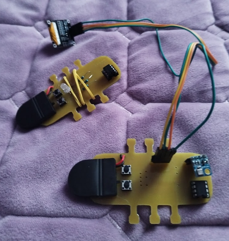
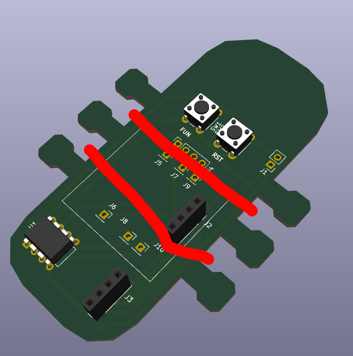
this is a hairclip that can be used as either a mood indicator, a tamagotchi, or a portable weather station. well, not a hairclip by itself -- a pcb that can be attached onto a hairclip with rubber bands. it has multiple firmware modes available, all of which let you use the device in their own unique ways. it is based on the attiny85 chip, which isn't too powerful but is more than enough for this.
first of all, get all the required components (listed in bom.xml, disregard components you don't need) and build it! the gerber files and the source project files are in this repo, too (see kicad/). here are some notes:
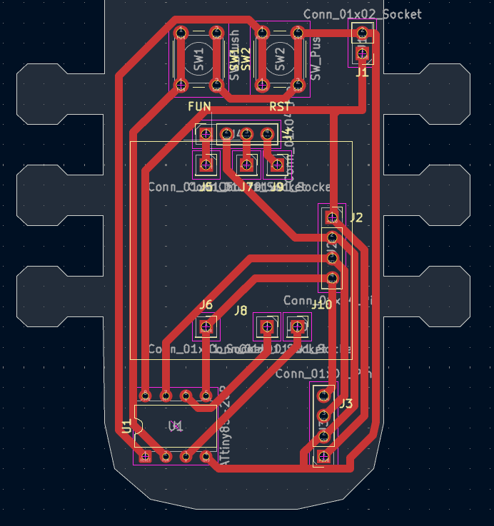
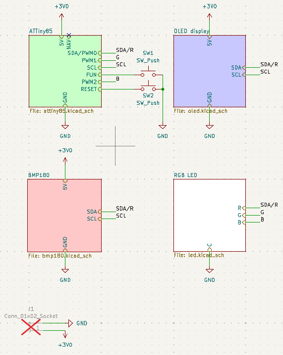
you can then attach it to a hairclip using small rubber bands with the grooves on the pcb (the "legs" of the louse).
once you have built it, flash the attiny85 with the appropriate firmware from firmware/. (note: if you want to permanently solder the attiny85 to the board, flash it before that! it'll be very hard to do it otherwise.)
then just turn on the battery and enjoy!!
| mode | FUN | RST |
|---|---|---|
| mood indicator | - | change color/mood |
| weather station | - | turn on |
| tamagotchi | play with | feed/turn on |
i have an old mood indicator hairclip (inspired by a pi pico hot glued to a hairclip, which was gifted to me by a friend), which also has an attiny85. i built it around december of 2025, and wanted to push the concept of wearable hairclips even further ever since then. this is my next attempt, hopefully it's actually good!!
| Qty | Value | Footprint | References |
|---|---|---|---|
| 6 | Conn_01x01_Socket | Connector_PinSocket_2.54mm:PinSocket_1x01_P2.54mm_Vertical | J5, J6, J7, J8, J9, J10 |
| 3 | Conn_01x04_Pin | Connector_PinSocket_2.54mm:PinSocket_1x04_P2.54mm_Vertical | J2, J3, J4 |
| 2 | SW_Push | Button_Switch_THT:SW_PUSH_6mm | SW1, SW2 |
| 1 | ATtiny85-20P | Package_DIP:DIP-8_W7.62mm | U1 |
| 1 | Conn_01x02_Socket | Connector_PinHeader_2.54mm:PinHeader_1x02_P2.54mm_Vertical | J1 |
It measures 56.7 × 83.9 mm and has 2 copper layers, 1.6 mm thick.
13 parts, built around the ATTINY85-20PU. The full list of its parts is on this page, with links to each part's symbol and footprint where PCBKit's library has them.
From the Milk-Cool/atlice repository on GitHub, at the commit this page was made from: the board is kicad/atlice.kicad_pcb and its schematic kicad/atlice.kicad_sch. PCBKit opens the board in the browser, with nothing to install.
Its repository publishes it under the MIT licence: you may reuse it on that licence's terms (keep the author's notice, and for a copyleft licence share your changes alike).
bwack/C64-Switchless-Multi-Kernal-27C256-adapter
Kernal switcher for the C64/C64C/C128

plusvic/simplebus2-intercom
General description of the Simplebus2 protocol used by some Comelit's intercoms. Hardware for retransmitting Simplebus2 messages over UART.

osmocom/osmocom-analog
Software Implementation of analog cellular telephony systems like NMT, TACS, IMTS, A/B/C-Netz; mirror of https://gitea.osmocom.org/cellular-infrastructure/osmocom-analog

strickyak/jerboa-attiny85-mod-synth
Modular Synthesizer using an ATtiny85 chip for each module.


Hack-a-Day/Remoticon_KiCad_Blender
support files for the 2020 Remoticon KiCad to Blender > PCB renders workshop
