2 layers25 × 25 mm
Sl25
TECHOTAKU182/Pilot-Light
本版与 ../../enclosure/sl25trafficrevb/ 外壳配套,取代 Rev A 的偏上小灯珠设计。PCB 正面只有一颗位于几何中心的 WS2812B-V5,其他电子元件和 USB-C 均在背面。 板框仍为 25×25 mm,双层、1.6 mm 厚,两个 M2 孔的位置保持原接口。
24 parts1
 milar111/L.I.P.S.13
OpenSource Affordable SipAndPuff device: Linear Interface for Paralysis Support
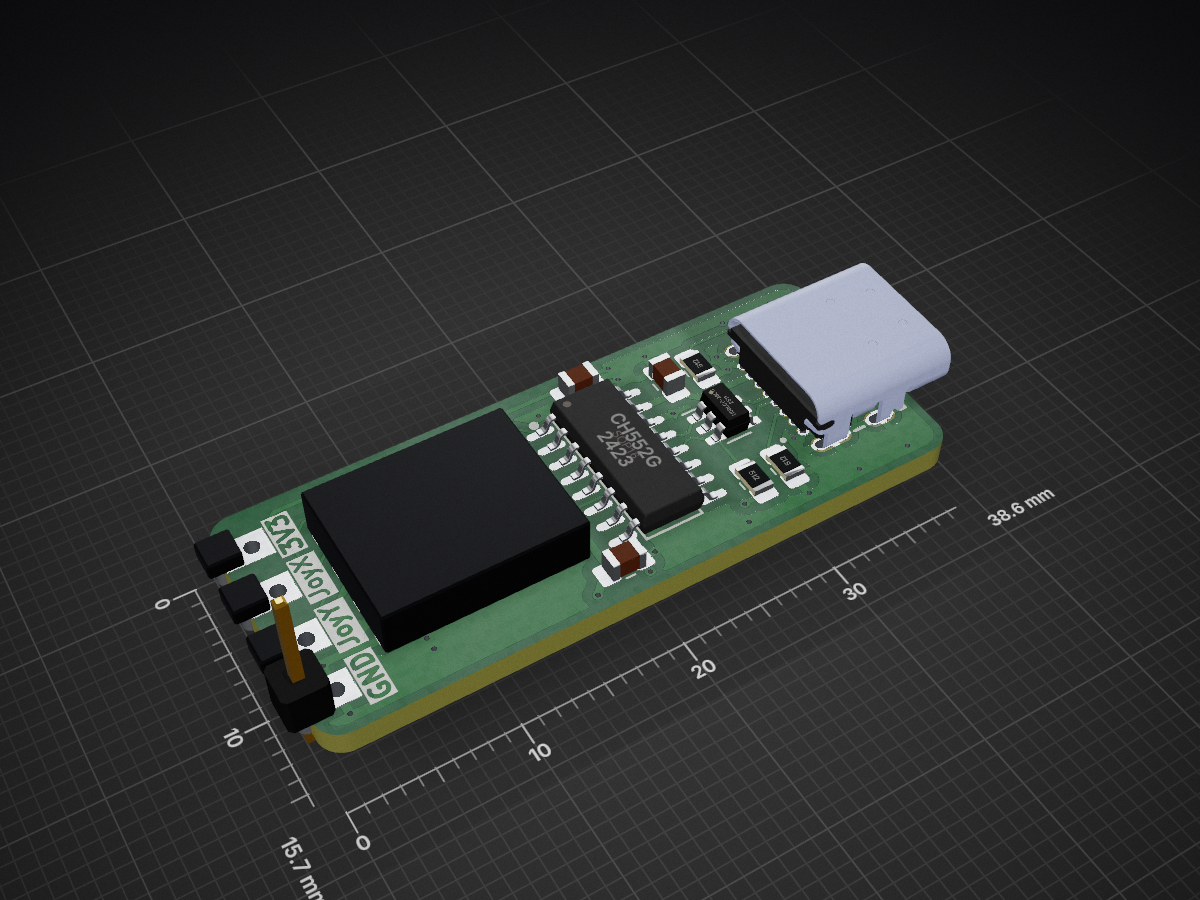
LIPS V3.2 is an open-source printed circuit board by milar111, from the milar111/L.I.P.S. repository on GitHub. It is a 2-layer board of 38.6 × 15.7 mm with 21 parts on 33 nets, routed with 154 tracks and 39 vias.
It is built around the CH552G and USBLC6-2SC6. Its parts include 4 capacitors, 3 resistors, 2 ICs and 1 connector. It belongs with the 8051 (CH55x, STC, AT89) boards of this library.


L.I.P.S. is an open-source assistive device that lets people with limited hand or arm mobility control a computer using sip and puff breath pressure combined with a mini analog joystick. It plugs in over USB and presents itself as a standard keyboard and mouse — no drivers, no software installation, works on any operating system.
USB VID/PID notice: The Vendor ID and Product ID used in this project are temporary placeholders pending official registration with pid.codes.
L.I.P.S. was designed for people who cannot use a conventional keyboard or mouse. The device reads breath pressure through a silicone mouthpiece, maps each sip and puff gesture to a configurable action (key press, mouse click, or scroll), and maps joystick movement to the mouse cursor.
Everything is configurable without re-flashing. A web app connects to the device over USB serial and lets you change what each sensor does — no code editing required.
Key properties:
Output
Non-Volatile Storage
| Parameter | Value |
|---|---|
| Core | 8051, 24 MHz |
| Package | SOP-16 |
| Supply | 3.3 V (internal LDO from 5 V USB) |
| USB | Native full-speed USB engine |
| ADC | 6 channels, 8-bit |
| Non-volatile | 128-byte EEPROM |
The CH552G was chosen for its native USB hardware (no external USB chip needed) and good Arduino ecosystem support via the CH55xDuino framework.
Each breath input uses an MPXV7002DP differential pressure sensor:
Each sensor is decoupled with a 100 nF capacitor on the supply pin. Port B is left open to atmosphere.
A 2-axis hall effect joystick with center detent:
R over the serial protocolPin layout (viewed from the front, stem pointing up): each potentiometer has three legs — GND, SIG, VCC.
| Parameter | Value |
|---|---|
| Connector | USB-C (16-pin SMD) |
| ESD protection | USBLC6-2SC6 |
| VID | 0x1209 (temporary — see notice at top) |
| PID (Single) | 0xC55B (temporary) |
| PID (Dual) | 0xC55C (temporary) |
| PID (Plus) | 0xC55D (temporary) |
| USB class | Composite: HID Keyboard + HID Mouse + CDC Serial |
USB-C CC pins use 5.1 kΩ pull-down resistors — no power-delivery negotiation needed, works with any standard USB-C cable.
The PCB was designed in KiCad. There are several revisions in this repo:
A standard 2-layer PCB ordered as-is from any fab house is all that's needed to run the device — no special stackup, no impedance control, no additional components. The board is powered entirely over USB; no external power supply or charger is required.
The current V3.x revisions include Castellated holes, which make soldering easier but increase the PCB fabrication cost slightly. They can be removed from the design without affecting functionality if you want to reduce cost.
Each PCB revision includes an interactive BOM (bom/ibom.html) inside its folder — open it in a browser to see component placement and reference designators before ordering or assembling.
Production files (gerbers, BOM, pick-and-place positions, and IPC netlist) are ready to upload directly to your fab house:
| Revision | Gerbers | BOM | Positions | Netlist |
|---|---|---|---|---|
| V3 | gerber.zip | BOM.csv | positions.csv | netlist.ipc |
| V3.1 | gerber.zip | BOM.csv | positions.csv | netlist.ipc |
| V3.2 | gerber.zip | BOM.csv | positions.csv | netlist.ipc |
Three firmware variants exist. Choose the one that matches your PCB revision:
| Variant | Sensors | Sketch | USB PID |
|---|---|---|---|
| SINGLE | 1 | code/1sensor/1sensor.ino | 0xC55B |
| DUAL | 2 | code/dualVariant/dualVariant.ino | 0xC55C |
| PLUS | 2 | code/plusVariant/plusVariant.ino | 0xC55D |
SINGLE and DUAL/PLUS differ in which CH552 pins are used for sensors. DUAL and PLUS have identical behavior but a rotated pin layout to match different PCB orientations.
docs/PROTOCOL.md) that the web configurator uses to read and write settings without re-flashing.The following are stored in the CH552's internal EEPROM and survive power cycles and firmware re-flashes:
Sensor action assignments (what each sip/puff does) are configured via the web tool and stored as well. On a blank device defaults are: puff → left click, sip → right click.
The enclosure is 3D printed and split into three parts: a head (holds the mouthpiece), a top lid, and a bottom lid. STL files are organised per variant:
| Variant | Folder |
|---|---|
| SINGLE | enclosure/1sensor/ |
| DUAL | enclosure/dualVariant/ |
| PLUS | enclosure/plusVariant/ |
Material: Both PLA and RESIGN have been tested and work. Use whatever you have available.
Print settings: The values below are examples — infill percentage, wall count, and similar settings have no meaningful impact on function since this is a shell with no structural loads.
| Setting | Example value |
|---|---|
| Layer height | 0.2 mm |
| Walls | 3 perimeters |
| Infill | 15–25% |
| Supports | Only where needed |
The mouthpiece channel may need to be cleared with a 3 mm drill bit if your printer leaves sag in the bridge.
For hand-soldering the PCB from bare board, see
docs/PCB_SOLDERING.mdfirst. The steps below assume the PCB is already fully assembled.
Cut wires at least 3–5 cm long and strip the ends. Solder the wires to the joystick first, then position it inside the case and route the wires to the PCB pads — adjusting length and orientation as you go before committing to the PCB solder joint. The final wire run from joystick to PCB should end up no more than ~1.5 cm once everything is seated. VCC and GND must be connected correctly. The signal lines (X and Y axes) can be swapped in software, so wire them however is most convenient given your layout.
The joystick has two axes, so there are two GND pins and two VCC pins — but they are the same net. Bridge the two GND legs together and the two VCC legs together at the joystick, so only one GND wire and one VCC wire need to run to the PCB.
Do not put the case on yet. Flash the firmware (see Section 8) and verify that:
Fix any issues now while the board is still accessible.
Take the silicone tube and push it through the sensor hole in the case from the outside, pushing it further in than it needs to go — leave extra length inside.
Insert the PCB into the case by leading with the USB-C connector end. Once the connector is aligned with its cutout, connect the silicone tube to the pressure sensor port.
While pulling the silicone tube back out from the outside of the case (to take up the slack), simultaneously press the PCB toward the case from the inside. Continue until you hear and feel a snap — this is the PCB seating flush against the case walls.
Move the joystick module into its position in the case. Check that it fits — depending on how the case was printed there may be a small amount of material to trim or sand. Once confirmed, apply super glue (cyanoacrylate) to secure it in place and hold for a few seconds until set.
Apply glue to the contact points shown in the image below, align the lid, and hold it in place for a few seconds.
| Component | Notes | Link |
|---|---|---|
| CH552G (SOP-16) | Main microcontroller | |
| MPXV7002DP | Differential pressure sensor | |
| USB-C connector (16-pin SMD) | ||
| 5.1 kΩ resistor × 2 | USB-C CC pull-downs | |
| USBLC6-2SC6 | USB ESD protection | |
| 100 nF capacitor (0603) | Sensor decoupling, one per sensor | |
| Analog joystick module | 2-axis with center detent | |
| Silicone food-grade tubing, 3 mm ID | At least 13 cm per sensor input — cut to fit during assembly | |
| Mouthpiece tip | Food-grade silicone, replaceable | |
| M2 × 6 mm screws × 4 | Enclosure fasteners |
See the interactive BOM in each PCB revision's bom/ibom.html for exact reference designators.
The L.I.P.S. web tool lets you select your device variant, automatically puts the device into bootloader mode, and flashes the correct firmware. It also has a settings page for configuring sensor actions.
Website Here : https://projectlips.me/
One-time setup:
https://raw.githubusercontent.com/DeqingSun/ch55xduino/ch55xduino/package_ch55xduino_mcs51_index.jsonBoard settings:
| Setting | Value |
|---|---|
| Board | CH55x Boards → CH552 |
| USB Settings | USER CODE w/ 266B USB ram |
Entering bootloader mode:
You almost never need to do this manually. A board fresh from the manufacturer enters bootloader mode automatically on its very first plug-in. After that, the configurator's Enter Bootloader button sends a serial command to reset into bootloader without touching the hardware.
Uploading: click Upload (→) in Arduino IDE. The port is detected automatically.
For full details see docs/ARDUINO_SETUP.md.
| Path | Contents |
|---|---|
code/ | Firmware — one Arduino sketch per variant, each with its USB library |
pcb/ | KiCad schematics, PCB files, iBOM, and production files for each revision |
enclosure/ | STL files per variant for 3D printing |
configurator.html | Web tool to enter bootloader mode (Chrome/Edge) |
docs/PCB_SOLDERING.md | Hand-soldering the PCB |
docs/ARDUINO_SETUP.md | Compiling and flashing from Arduino source |
docs/PROTOCOL.md | USB serial protocol spec |
docs/PIN_MAP.md | CH552 pin assignments and PCB compatibility matrix |
docs/WIRING.md | Block diagrams and wiring tables |
docs/SCS_ID.md | How to customize the USB device name |
scripts/ | Release packaging scripts (bash + PowerShell) |
.github/workflows/ | CI — compiles firmware and creates release packages |
R over serial.#define DEADZONE in the firmware (try 8 or 10).#define THRESH_PUFF / THRESH_SIP. If the sensor is noisy, raise the absolute values.Quick index of everything in docs/:
| File | What it's for |
|---|---|
PCB_SOLDERING.md | Step-by-step hand-soldering guide for the bare PCB |
ARDUINO_SETUP.md | One-time Arduino IDE setup and manual flashing instructions |
WIRING.md | Block diagrams and wiring tables for all connections |
PIN_MAP.md | CH552 pin assignments and which PCB revision uses which pins |
PROTOCOL.md | USB serial command protocol used by the web configurator |
SCS_ID.md | How to change the USB device name that appears on your computer |
This project is licensed under Creative Commons Attribution-NonCommercial-ShareAlike 4.0 International (CC BY-NC-SA 4.0).
You are free to share and adapt the material for non-commercial purposes, provided you give appropriate credit and distribute any adaptations under the same license.
| Qty | Value | Footprint | References |
|---|---|---|---|
| 4 | , , , | ||
| 4 | 100nF | Capacitor_SMD:C_0805_2012Metric_Pad1.18x1.45mm_HandSolder | C1, C2, C3, C4 |
| 4 | TestPoint | TestPoint:TestPoint_THTPad_1.7x1.7mm_Drill0.7mm | TP1, TP2, TP3, TP4 |
| 3 | 5k1 | Resistor_SMD:R_0805_2012Metric_Pad1.20x1.40mm_HandSolder | R1, R4, R5 |
| 2 | ~ | Package_SO:+-2kPaReal | XGZP6897A025HPDPN1, XGZP6897A025HPDPN2 |
| 1 | CH552G | CH552G:SOP-16_L10.0-W3.9-P1.27-LS6.0-BL | U1 |
| 1 | SolderJumper_2_Open | Jumper:SolderJumper-2_P1.3mm_Open_RoundedPad1.0x1.5mm | JP1 |
| 1 | USB4085-GF-A_REVB | USB4085_GF_A:GCT_USB4085-GF-A_REVB | J1 |
| 1 | USBLC6-2SC6 | Package_TO_SOT_SMD:SOT-23-6 | U3 |
TECHOTAKU182/Pilot-Light
本版与 ../../enclosure/sl25trafficrevb/ 外壳配套,取代 Rev A 的偏上小灯珠设计。PCB 正面只有一颗位于几何中心的 WS2812B-V5,其他电子元件和 USB-C 均在背面。 板框仍为 25×25 mm,双层、1.6 mm 厚,两个 M2 孔的位置保持原接口。

recepbugra24/usb-button-controller
A minimal USB HID keyboard board that reads two externally wired buttons and sends keystrokes to a host computer. No drivers required — the host enumerates it as a standard keyboard.


gowenrw/BSidesDFW_2019_Badge
This is where all the files for the BSidesDFW 2019 Badge will be stored. This includes code and art and cab and fab files. All the things.
It measures 38.6 × 15.7 mm and has 2 copper layers, 1.6 mm thick.
21 parts, built around the CH552G and USBLC6-2SC6. The full list of its parts is on this page, with links to each part's symbol and footprint where PCBKit's library has them.
From the milar111/L.I.P.S. repository on GitHub, at the commit this page was made from: the board is pcb/LIPS_V3.2/LIPS_V3.2.kicad_pcb and its schematic pcb/LIPS_V3.1/LIPS_V3.1.kicad_sch. PCBKit opens the board in the browser, with nothing to install.
Its repository states no licence, so its author keeps all rights: ask milar111 before reusing the design.