2 layers142.5 × 106.4 mm

 Mikuel210/Cody1
A robot for the next season of WRO Robomission Senior
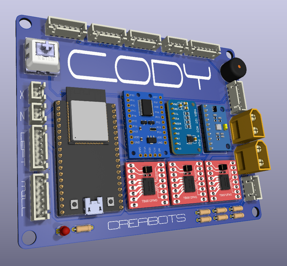
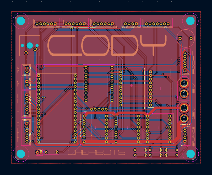
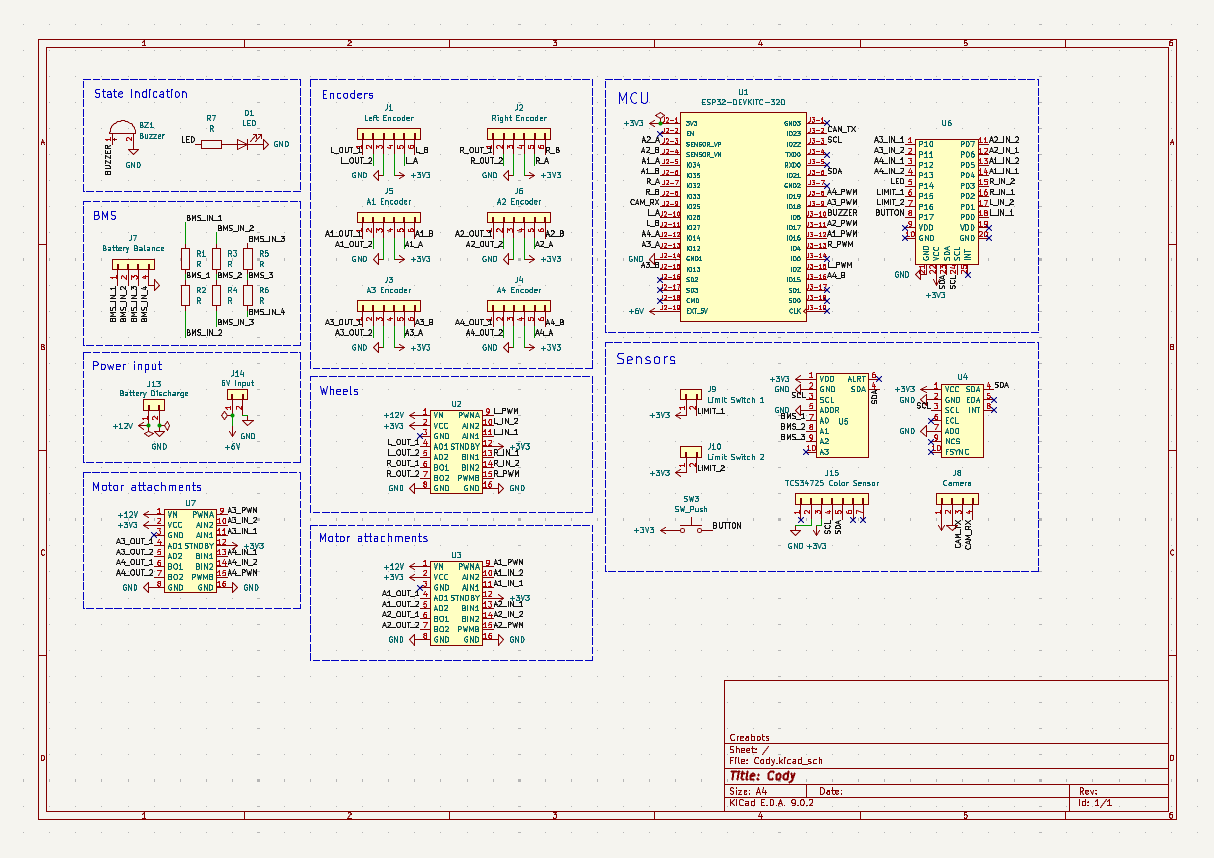
Cody is an open-source printed circuit board by Mikuel210, from the Mikuel210/Cody repository on GitHub. It is a 2-layer board of 125 × 99.9 mm with 34 parts on 92 nets, routed with 602 tracks and 54 vias.
Its parts include 13 connectors, 7 resistors, 7 ICs, 1 diode and 1 switch. It belongs with the robots and motor control boards and the ESP32 boards of this library.

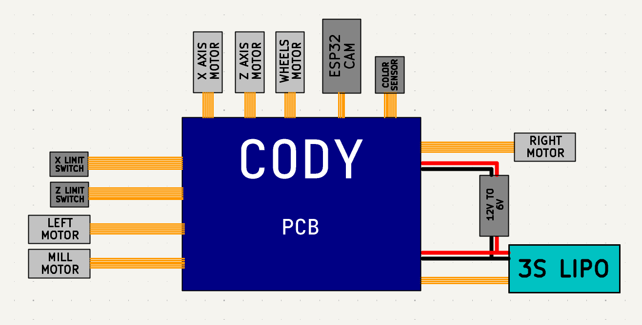
Cody is a robot for the next season of WRO Robomission Senior.
The World Robot Olympiad (WRO) is a global robotics competition. For the Robomission challenge, you have to design, build and program a robot to complete a set of challenges on a board in under 2 minutes. Cody is our attempt at making our best robot so far, and I'm designing it to be faster, more precise and more reliable than all of our previous.
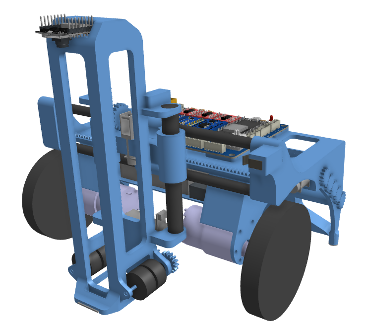
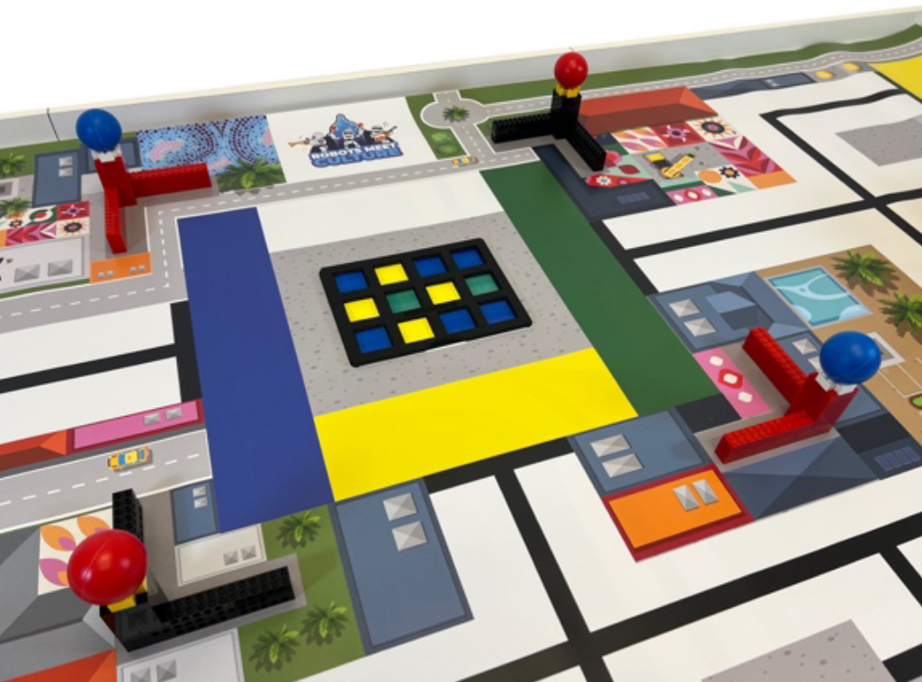
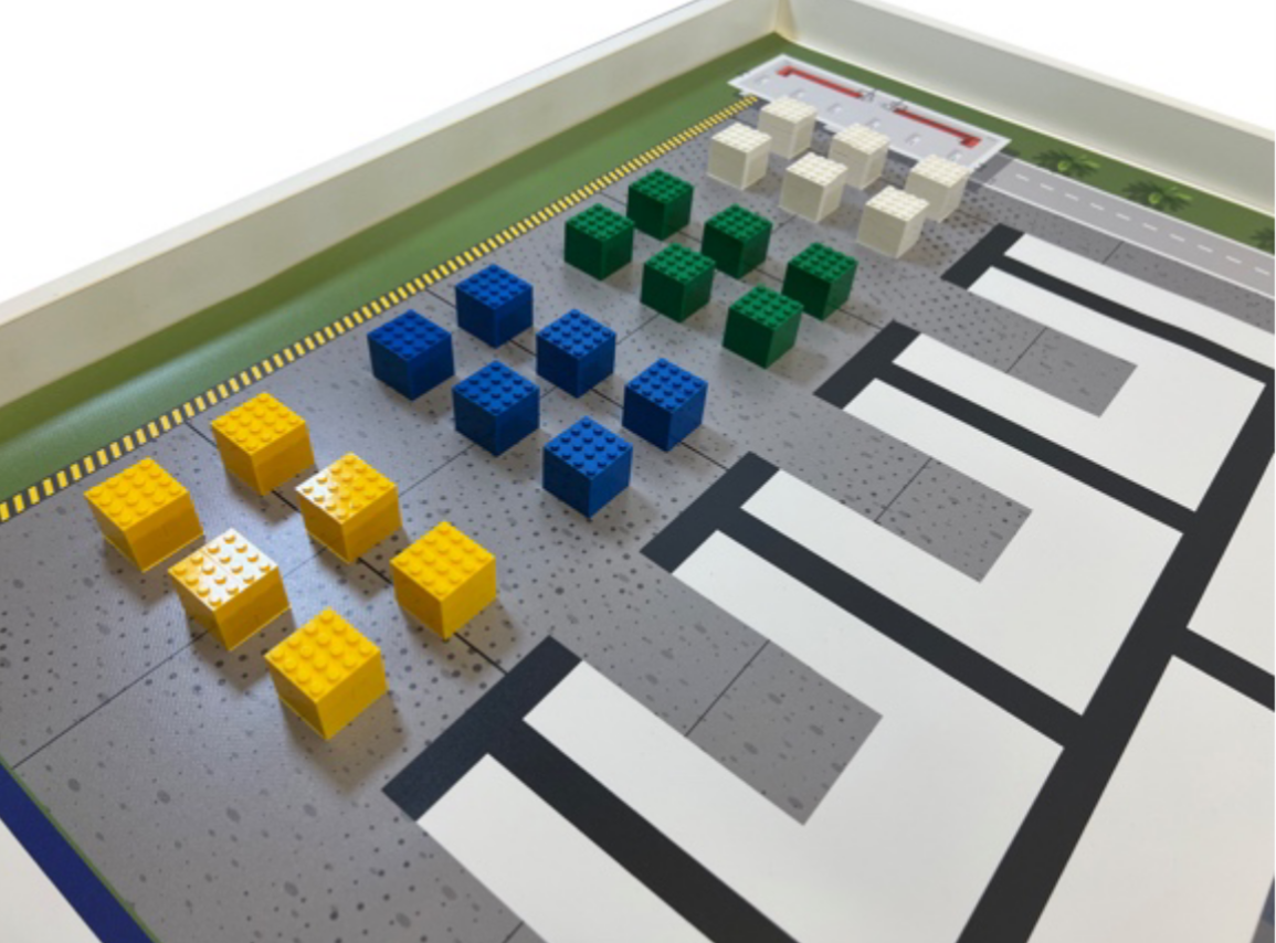
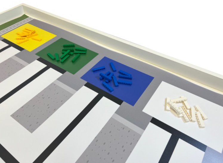
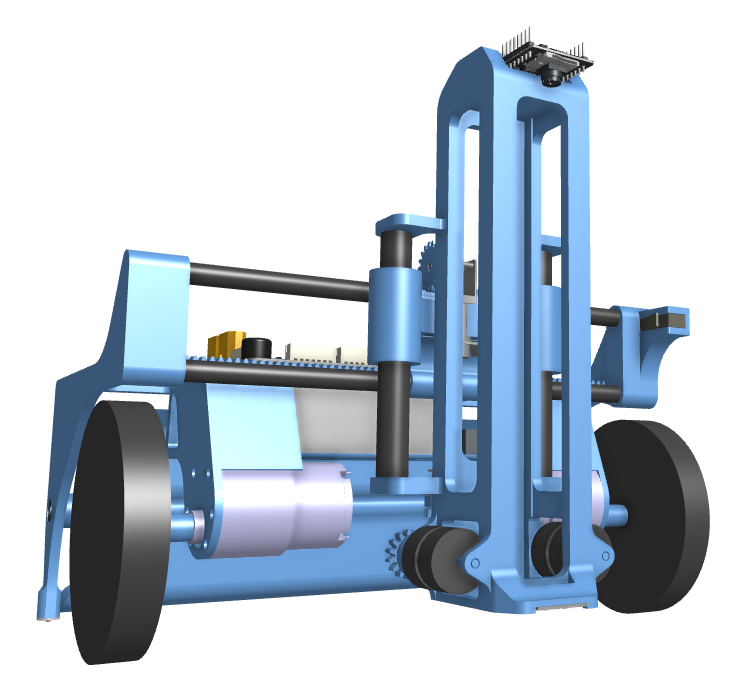
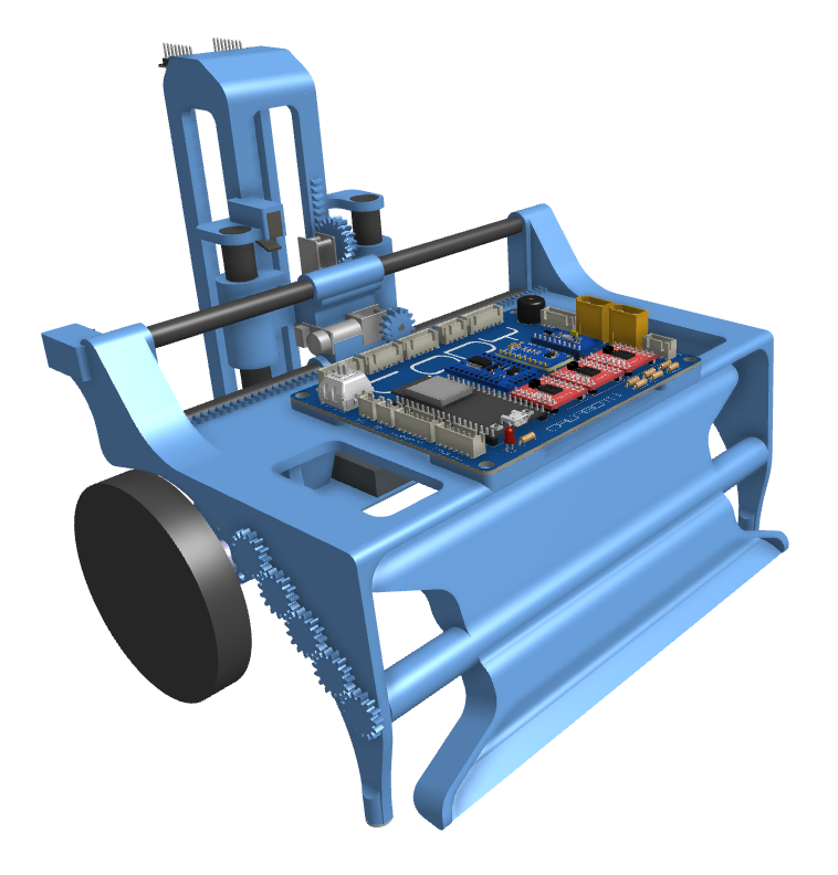
My team has been using Lego Spike since we started competing, but it's starting to show its limitations. Last year, we went to the international final for the first time. Robomission had opened up to all hardwares for the first time this year, which means other teams could make faster, more precise and more reliable robots than what we could possibly do with Lego. I'm designing this robot to be faster, more precise and more reliable than our previous robots with the power of open hardware.
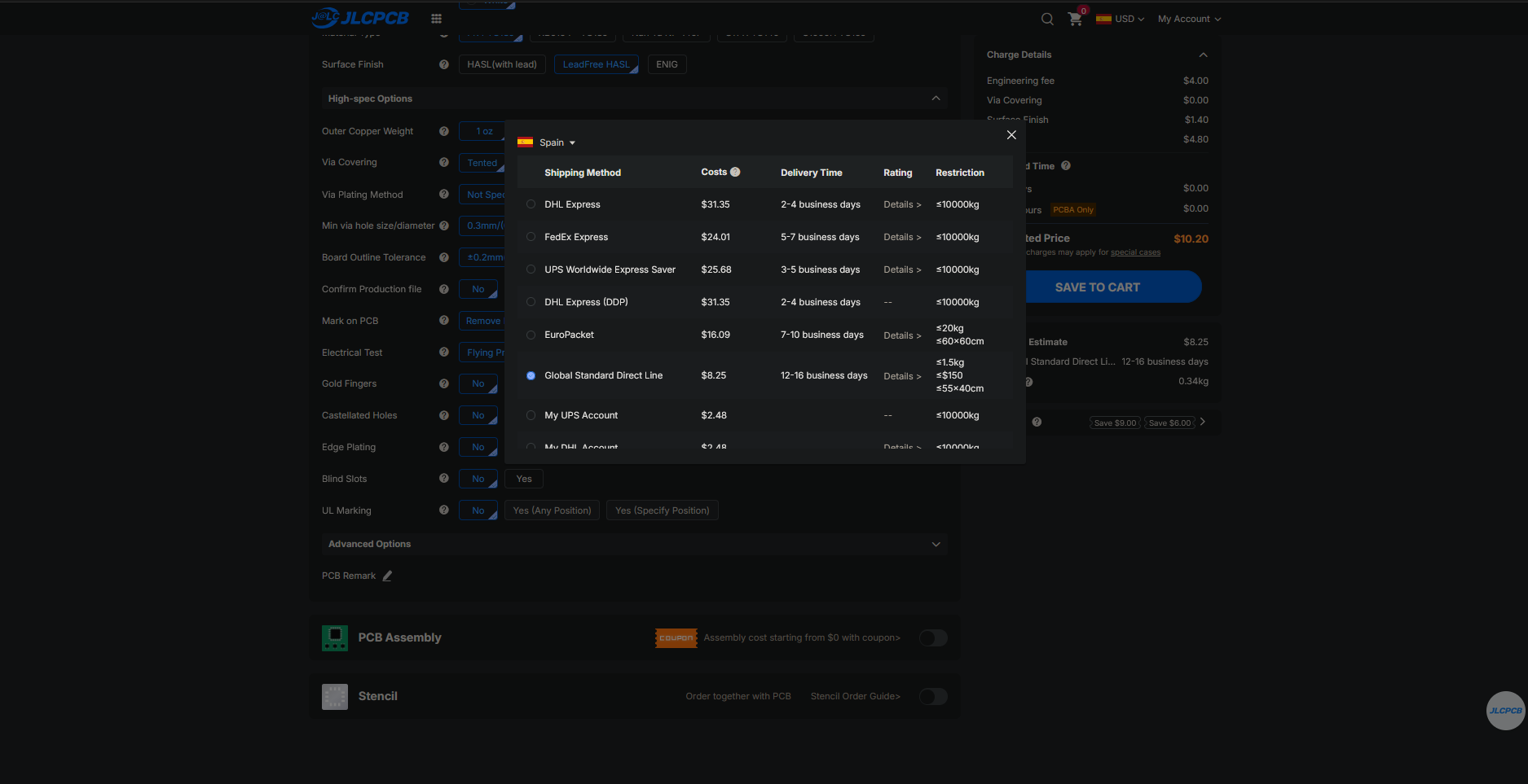
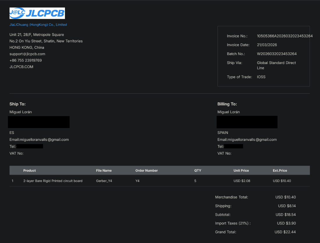
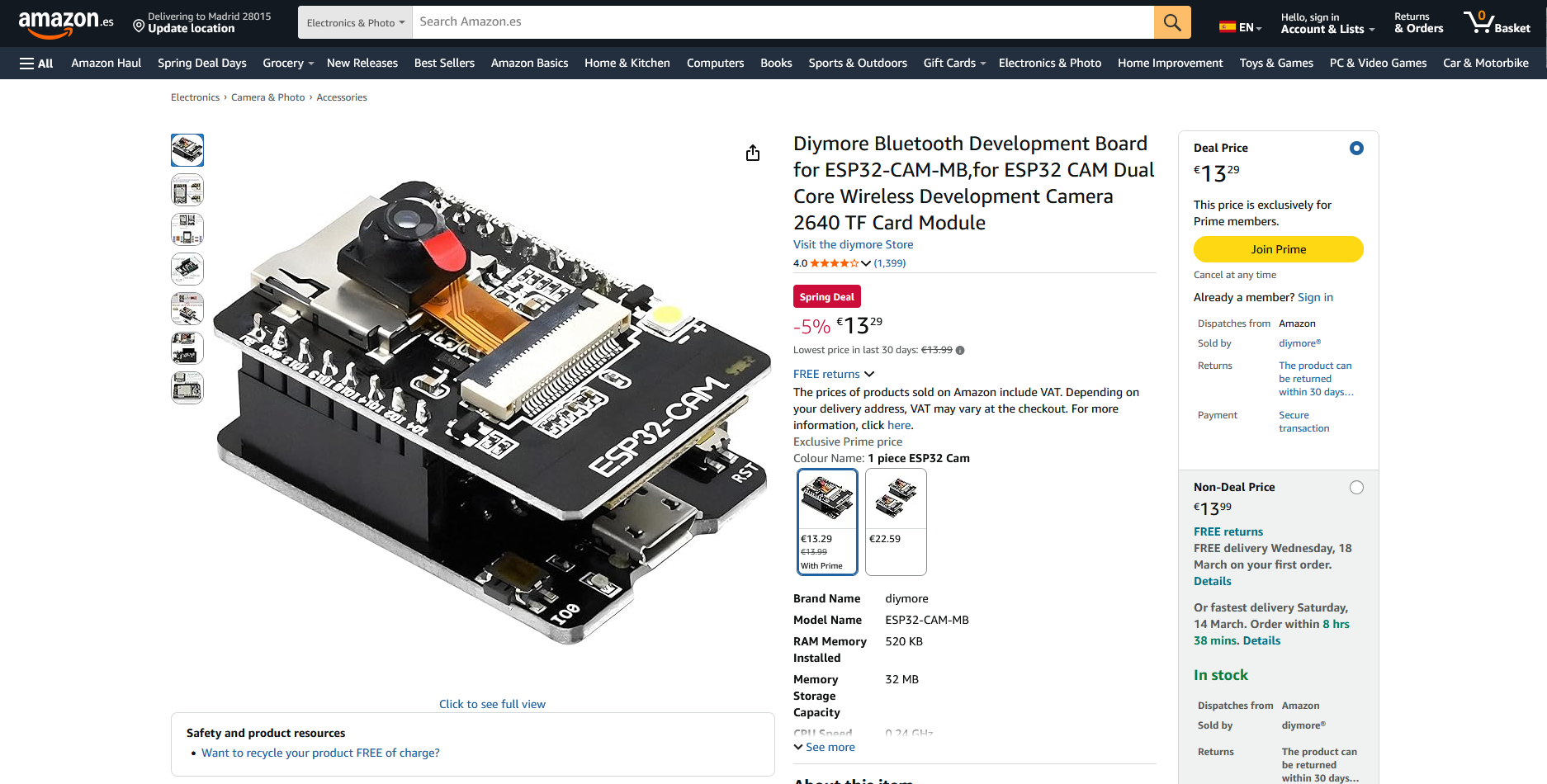
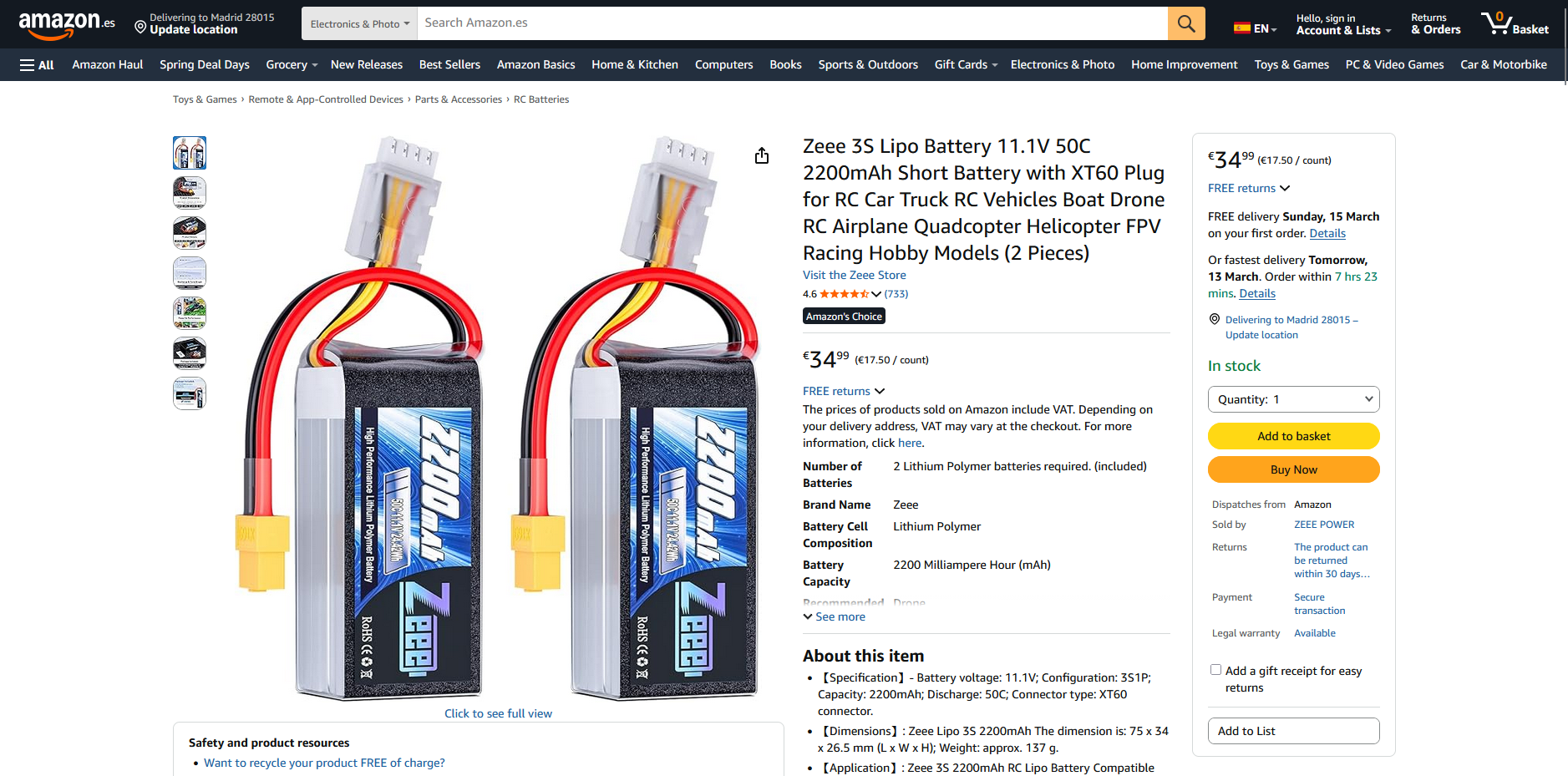
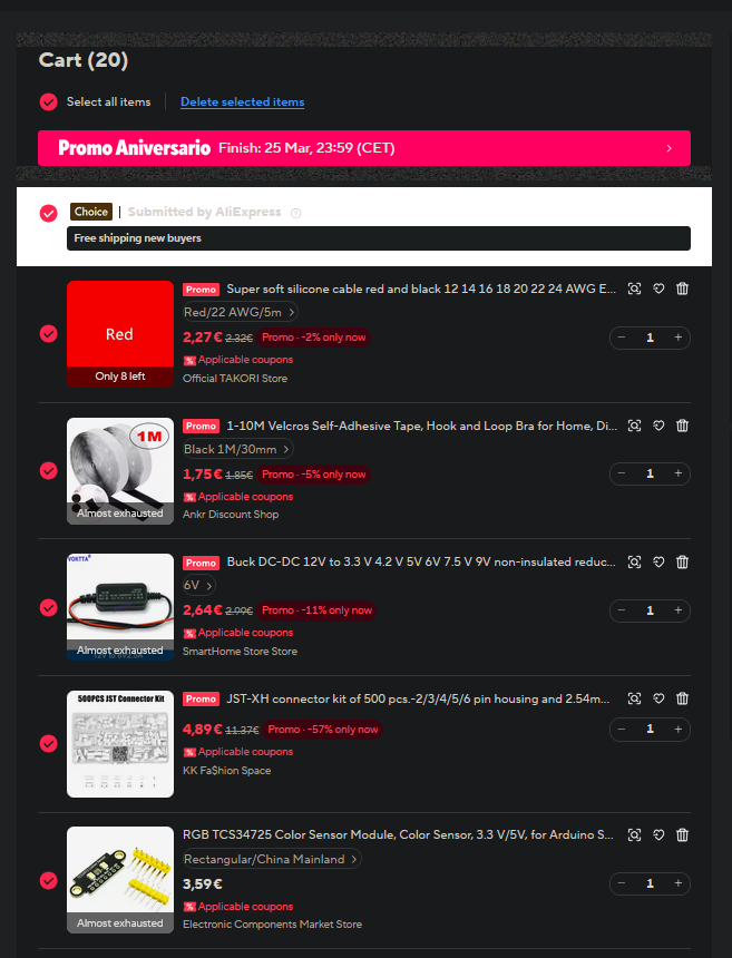
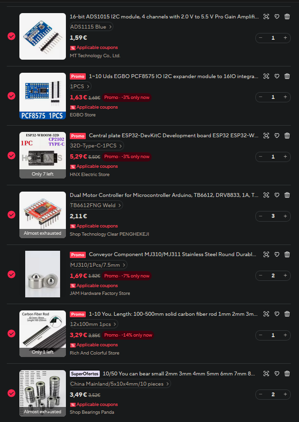
Note: I will be buying two of the carbon fiber rods above but AliExpress didn't feel like allowing me to add more than one to my cart at the moment
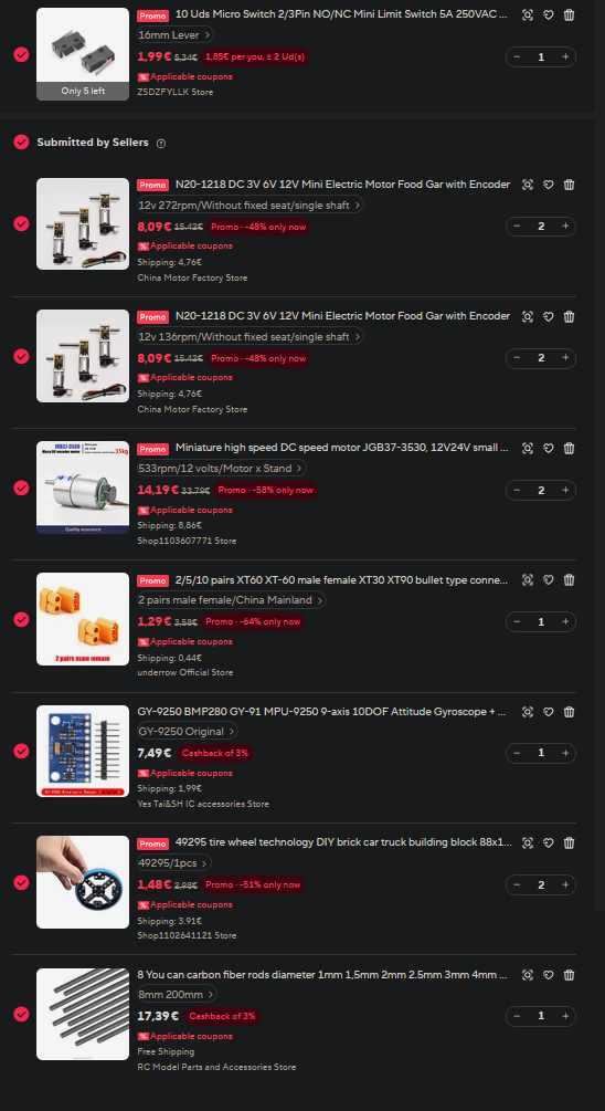
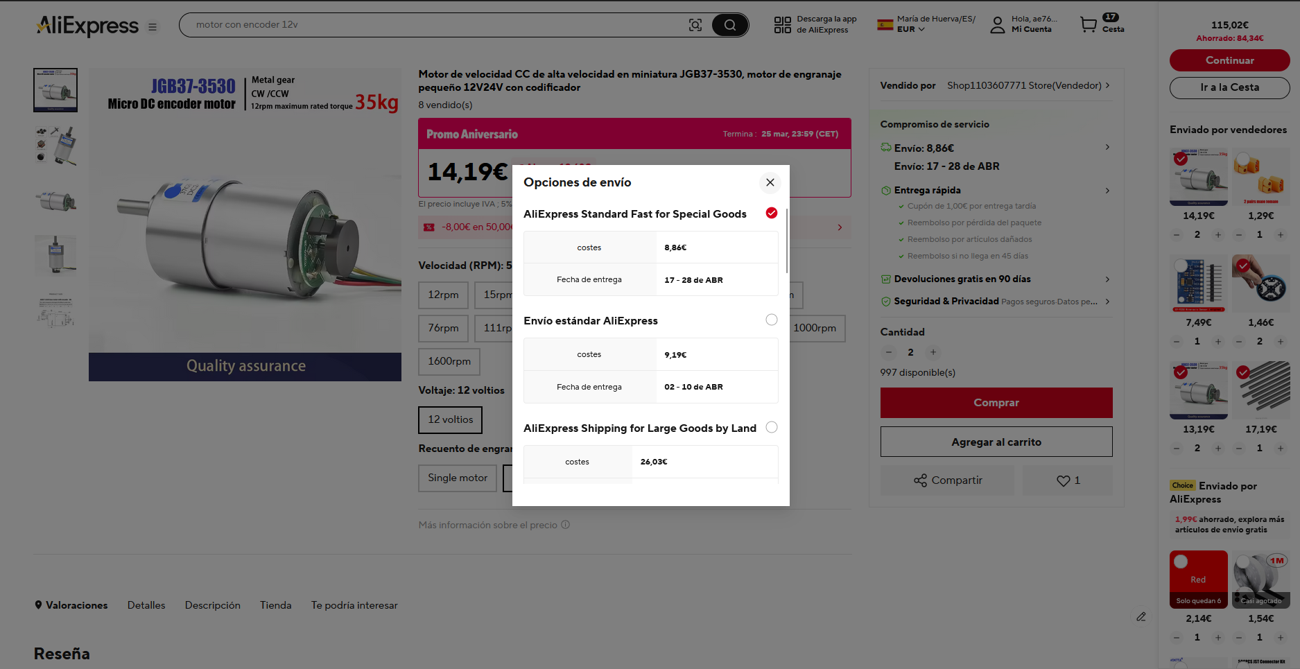
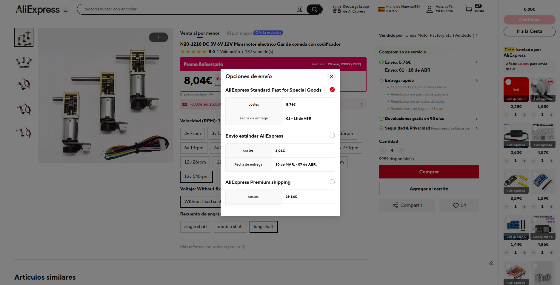
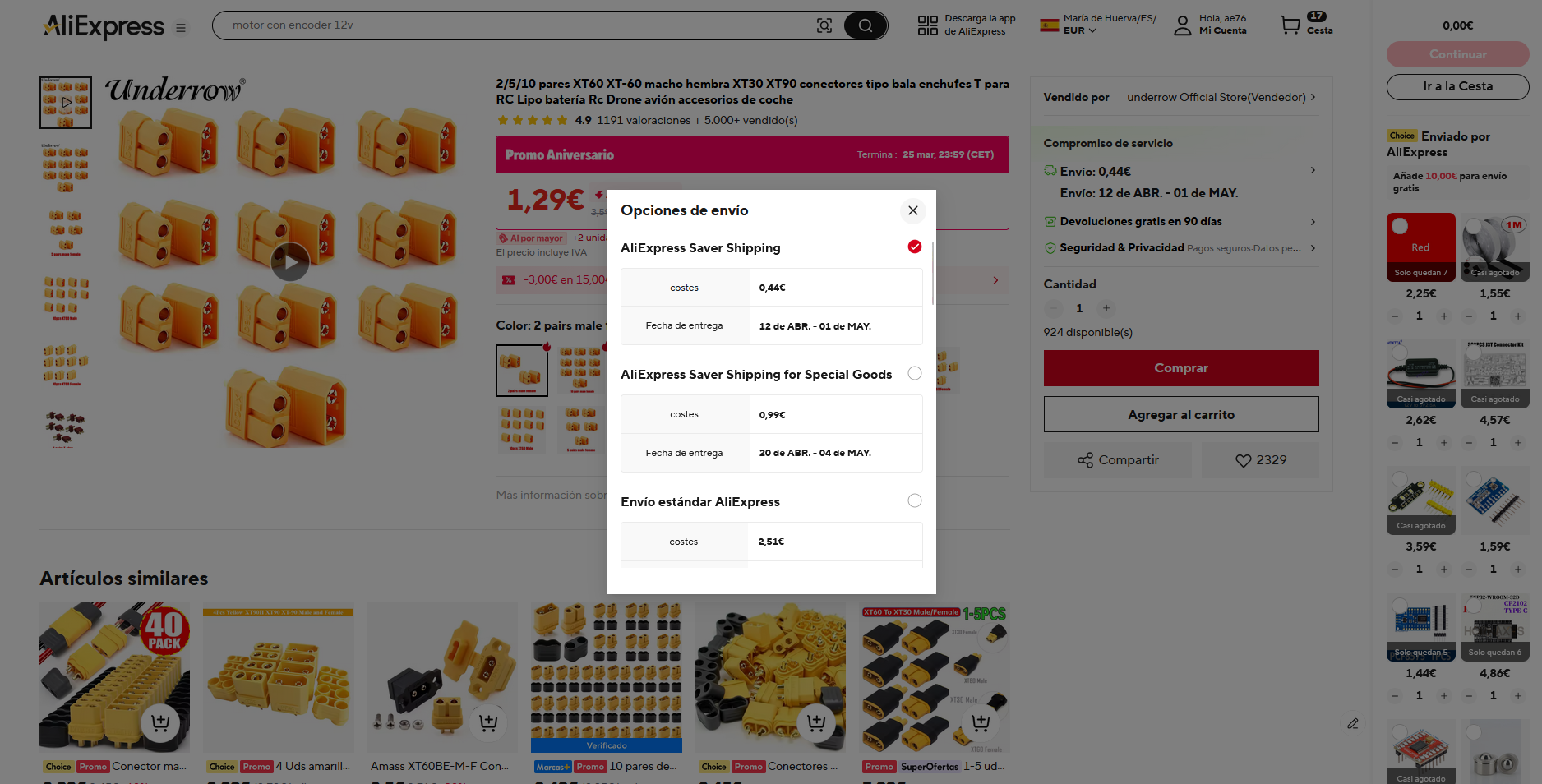
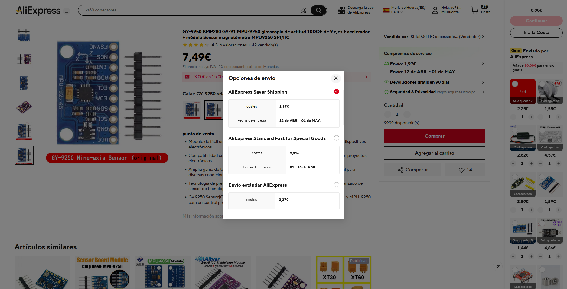
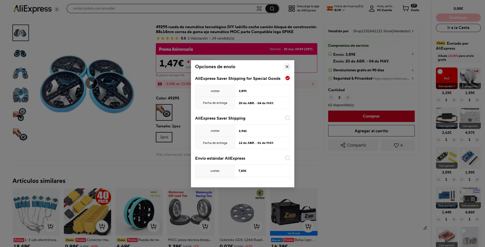
Note that the amount to buy might be higher than the amount to be used because the item is sold in bulk
Made with ❤️ for Blueprint thanks to Hack Club
| Qty | Value | Footprint | References |
|---|---|---|---|
| 7 | R | Resistor_THT:R_Axial_DIN0207_L6.3mm_D2.5mm_P7.62mm_Horizontal | R1, R2, R3, R4, R5, R6, R7 |
| 3 | ~ | Dependencies:TB6612FNG | U2, U3, U7 |
| 1 | 6V Input | Connector_AMASS:AMASS_XT60-M_1x02_P7.20mm_Vertical | J14 |
| 1 | A1 Encoder | Connector_JST:JST_XH_B6B-XH-A_1x06_P2.50mm_Vertical | J5 |
| 1 | A2 Encoder | Connector_JST:JST_XH_B6B-XH-A_1x06_P2.50mm_Vertical | J6 |
| 1 | A3 Encoder | Connector_JST:JST_XH_B6B-XH-A_1x06_P2.50mm_Vertical | J3 |
| 1 | A4 Encoder | Connector_JST:JST_XH_B6B-XH-A_1x06_P2.50mm_Vertical | J4 |
| 1 | Battery Balance | Connector_JST:JST_XH_B4B-XH-A_1x04_P2.50mm_Vertical | J7 |
| 1 | Battery Discharge | Connector_AMASS:AMASS_XT60-M_1x02_P7.20mm_Vertical | J13 |
| 1 | Buzzer | Buzzer_Beeper:Buzzer_12x9.5RM7.6 | BZ1 |
| 1 | Camera | Connector_JST:JST_XH_B4B-XH-A_1x04_P2.50mm_Vertical | J8 |
| 1 | ESP32-DEVKITC-32D | Dependencies:ESP32-DEVKITC-32D | U1 |
| 1 | LED | LED_THT:LED_D3.0mm | D1 |
| 1 | Left Encoder | Connector_JST:JST_XH_B6B-XH-A_1x06_P2.50mm_Vertical | J1 |
| 1 | Limit Switch 1 | Connector_JST:JST_XH_B2B-XH-A_1x02_P2.50mm_Vertical | J9 |
| 1 | Limit Switch 2 | Connector_JST:JST_XH_B2B-XH-A_1x02_P2.50mm_Vertical | J10 |
| 1 | Right Encoder | Connector_JST:JST_XH_B6B-XH-A_1x06_P2.50mm_Vertical | J2 |
| 1 | SW_Push | Button_Switch_Keyboard:SW_Cherry_MX_1.00u_PCB | SW3 |
| 1 | TCS34725 Color Sensor | Connector_JST:JST_XH_B7B-XH-A_1x07_P2.50mm_Vertical | J15 |
| 1 | ~ | Dependencies:PCF8575 | U6 |
| 1 | ~ | Dependencies:ADS1115 | U5 |
| 1 | ~ | Dependencies:GY-9250 | U4 |
The 30 most common of 34 parts.
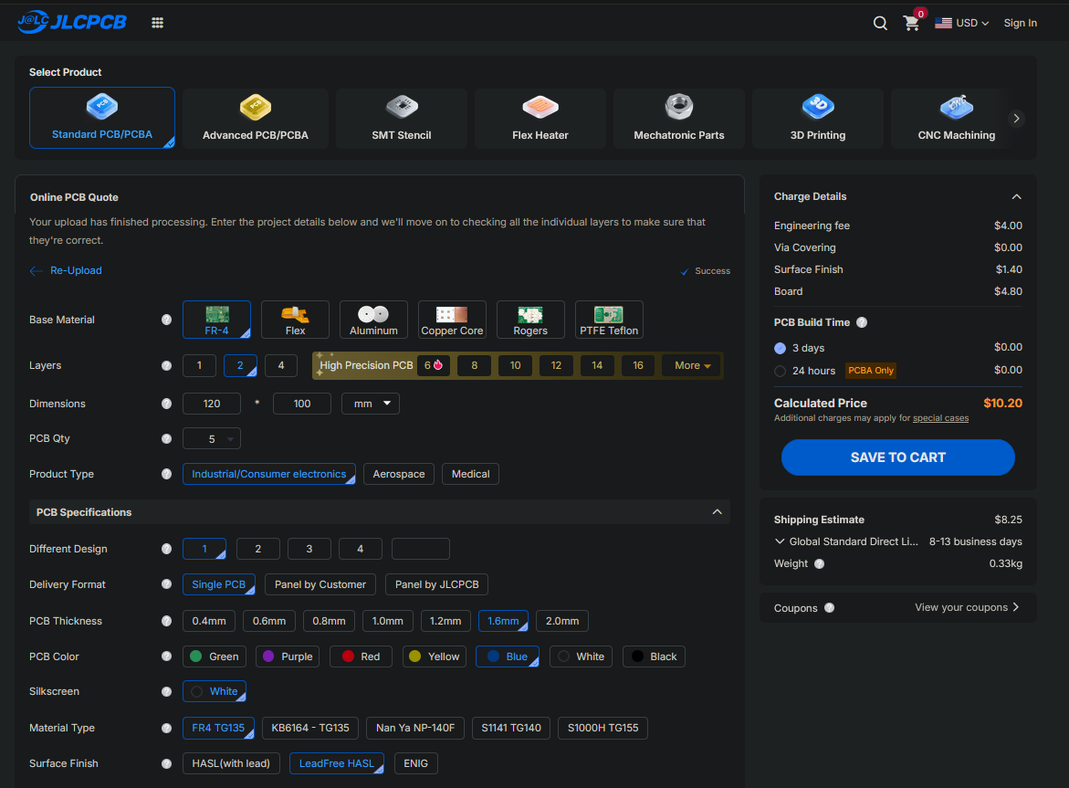
It measures 125 × 99.9 mm and has 2 copper layers, 1.6 mm thick.
34 parts. The full list of its parts is on this page, with links to each part's symbol and footprint where PCBKit's library has them.
From the Mikuel210/Cody repository on GitHub, at the commit this page was made from: the board is PCB/Cody.kicad_pcb and its schematic PCB/Cody.kicad_sch. PCBKit opens the board in the browser, with nothing to install.
Its repository states no licence, so its author keeps all rights: ask Mikuel210 before reusing the design.

FrameworkComputer/ExpansionCards
Reference designs and documentation to create Expansion Cards for the Framework Laptop

mntmn/amiga2000-gfxcard
MNT VA2000, an Open Source Amiga 2/3/4000 Graphics Card (Zorro II/III), written in Verilog

hackclub/OnBoard
💡 Join 1,000 teenagers and make your first PCB with a $100 grant!


strangeparts/niubi-headphones
Flexible circuit board design for adding a headphone jack to an iPhone 7


baldengineer/bit-preserve
Project for capturing vintage, classic, aka old computer schematics in KiCad.