2 layers335 × 218.6 mm
 mikey60/BW16-RTL8720DN-Module-Arduino61
BW16 (RTL8720DN) Module - Getting Started with Arduino
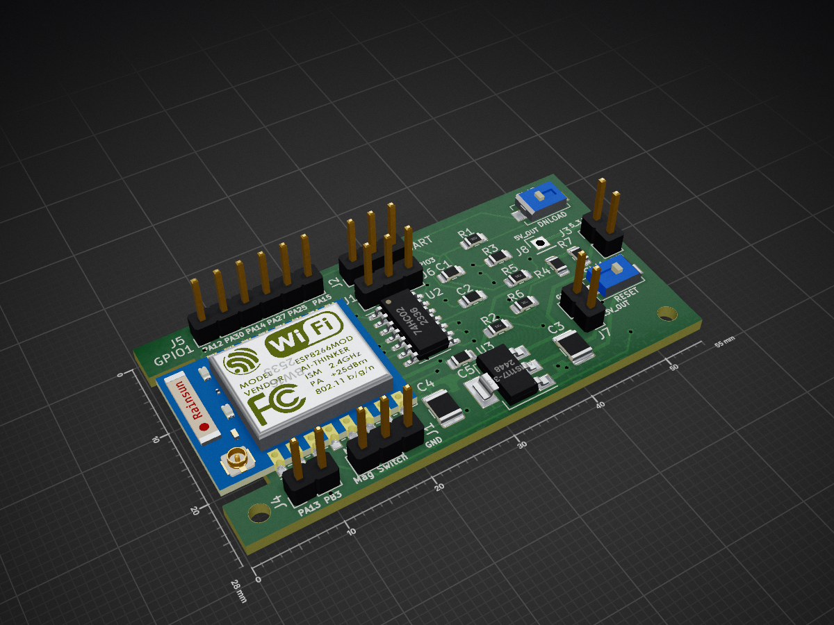
RTL8720DN multi function board is an open-source printed circuit board by mikey60, from the mikey60/BW16-RTL8720DN-Module-Arduino repository on GitHub. It is a 2-layer board of 55 × 28 mm with 27 parts on 23 nets, routed with 316 tracks and 53 vias.
It is built around the BW16, 74HC02 and AMS1117-3.3. Its parts include 8 connectors, 7 resistors, 5 capacitors, 3 ICs and 2 switches.


Revisions
March 3, 2021 - Implemented the recommendation from @moononournation that changes the variant.cpp file to be compatible with the SPI1 pin definition in the SPI.cpp file. This simplifies the sketches that use SPI so that the creation of another SPIClass is not required. So this is a 'major' change for the sketches that use SPI. A new 'modified variant.cpp can be found in the variant_cpp_mod folder. I also corrected and updated some comments in the sketches.
March 17, 2021 - Slightly updated the RTL8720DN multi function board with additional Power and ground connection holes. Added a sketch for rtlduino/BW16 board. The sketch describes the modifications to make the board more useful.
March 24, 2021 - Added RTL8720DN/BW16 and rtlduino pinout images supplied by @moononournation.
March 28, 2021 - Small corrections, add information on rtlduino modifications and link to @moononournation Instructable to program rtlduino.
July 7, 2021 - Include a modified variant.h file in the variant_cpp_mod folder so the AT serial can be used as noted by @flowlow in the issues.
Background
I decided to try the BW16 (RTL8720DN) module because it supports 5GHz WiFi and my 2.4 GHz WiFi band is very busy with old electronics, WiFi security cameras, neighbors networks, microwave oven and many IOT 2.4 GHz only (ESP8266 and ESP32) modules connected. My 2.4 GHz channel can quite often spike over to over 40% utilization whereas my 5GHz channel is less than 10%. I also recommend creating a second WLAN with only a 5 GHz channel. It should also use a different SSID than the main WLAN. That way the module can only connect to the 5 GHZ and won't connect to the 2.4 GHz because it has a stronger signal.
The module I purchased is from Digikey for $4.25 Part number 1597-102110419-ND, manufactured by Seeed Technology Co., Ltd. It can be purchased on ebay, AliExpress, and of course the Seed Studio website.
Getting Started with Arduino and BW16 Module


Before downloading you can interact with the BW16 module using pins 15 (PB2/LP_UART_RXD) and pin 16 (PB1/LP_UART_TXD) connected to the USB to 3.3v TTL adapter with AT commands. You can also interact with the Test Command Mode by connecting the USB to 3.3v TTL adapter to the TXD (PA7) and RXD (PA8) pins. See the txt files in the info folder for brief captures of the interactions. Note that once the BW16 module is downloaded with an arduino sketch those interfaces are no longer available unless you somehow reload the original firmware.
To put the module in the download mode:
  Press and hold the switch to PA7.
  Press and release the switch to the CHIP_EN pin.
  Release the switch to PA7.
A another way to use the BW16 module is to use an ESP8266 Burning Fixture Development Board but that requires some cuts, jumpers and a resistor to work properly. Then a separate 3.3 volt power supply and USB to 3.3v TTL adapter are not required.
The 'RTL8720DN multi function board' folder contains all the files for a 'general purpose' PCB that I created using KiCad for the door switch and MQTT Digital LED projects.
rtlduino module modifications - In my opinion the USB port should be connected to the LOG_TX and LOG_RX pins rather than the AT_TX and AT_RX pins. I don’t believe that many people use the AT port. The first thing I did is cut and jumper the board so the USB port was connected to the LOG port so I could do downloads and terminal interaction with the USB using Arduino. Also I replaced the zero ohm resistor in series with the burn switch with 1.8 Kohm to comply with the >1 Kohm of the ‘GPIO Pull Low Restriction’ of the RTL872xD data sheet. See the 'rtlduino_modifications.pdf' file in the Info folder. Another way to program the rtlduino can be found at https://www.instructables.com/RTL8720DN/.
| Qty | Value | Footprint | References |
|---|---|---|---|
| 2 | 0.47uf | Resistor_SMD:R_0805_2012Metric_Pad1.15x1.40mm_HandSolder | C1, C2 |
| 2 | 10K | Resistor_SMD:R_0805_2012Metric_Pad1.15x1.40mm_HandSolder | R5, R6 |
| 2 | 1Meg | Resistor_SMD:R_0805_2012Metric_Pad1.15x1.40mm_HandSolder | R3, R4 |
| 2 | 2.1mm | MountingHole:MountingHole_2.1mm | Hole1, Hole2 |
| 2 | 22uf | Resistor_SMD:R_1210_3225Metric_Pad1.42x2.65mm_HandSolder | C3, C4 |
| 1 | 0 | Resistor_SMD:R_0805_2012Metric_Pad1.15x1.40mm_HandSolder | R7 |
| 1 | 0.1uf | Resistor_SMD:R_0805_2012Metric_Pad1.15x1.40mm_HandSolder | C5 |
| 1 | 1K | Resistor_SMD:R_0805_2012Metric_Pad1.15x1.40mm_HandSolder | R2 |
| 1 | 2K | Resistor_SMD:R_0805_2012Metric_Pad1.15x1.40mm_HandSolder | R1 |
| 1 | 74HC02 | Package_SO:SOIC-14_3.9x8.7mm_P1.27mm | U2 |
| 1 | AMS1117-3.3 | Package_TO_SOT_SMD:SOT-223-3_TabPin2 | U3 |
| 1 | BW16 | RTL8720DN:BW16 | U1 |
| 1 | DNLOAD | Button_Switch_SMD:SW_SPST_EVQPE1 | SW2 |
| 1 | GPIO1 | Connector_PinHeader_2.54mm:PinHeader_1x06_P2.54mm_Vertical | J5 |
| 1 | GPIO2 | Connector_PinHeader_2.54mm:PinHeader_1x02_P2.54mm_Vertical | J4 |
| 1 | GPIO3 | Connector_PinHeader_2.54mm:PinHeader_1x03_P2.54mm_Vertical | J6 |
| 1 | Mag Switch | Connector_PinHeader_2.54mm:PinHeader_1x03_P2.54mm_Vertical | J1 |
| 1 | Power | Connector_PinHeader_2.54mm:PinHeader_1x02_P2.54mm_Vertical | J3 |
| 1 | Pwr | Connector_PinHeader_2.54mm:PinHeader_1x01_P2.54mm_Vertical | J8 |
| 1 | Pwr | Connector_PinHeader_2.54mm:PinHeader_1x02_P2.54mm_Vertical | J7 |
| 1 | RESET | Button_Switch_SMD:SW_SPST_EVQPE1 | SW1 |
| 1 | UART | Connector_PinHeader_2.54mm:PinHeader_1x03_P2.54mm_Vertical | J2 |

Toolauth/wing-combo
A large Feather Wing board that can control tools and helps manage authorization in a community workshop

chatelao/xDuinoRail-Decoder
The friendly decoder development plattform for model railroad tinkers.


AvalonSemiconductors/AS2650-bring-up
Hardware and Software used during bring-up of the GFMPW-0 AS2650.

slu4coder/Minimal-64x4-Home-Computer
My DIY TTL home computer with VGA and PS/2 and 4x the processing power of a Commodore C64 or Apple II.

slu4coder/Minimal-UART-Computer-1-2
Legacy: Version 1 and 2 of my TTL-only CPU featuring UART I/O, an expansion port, 512KB SSD at up to 10MHz clock speed

It measures 55 × 28 mm and has 2 copper layers, 1.6 mm thick.
27 parts, built around the BW16, 74HC02 and AMS1117-3.3. The full list of its parts is on this page, with links to each part's symbol and footprint where PCBKit's library has them.
From the mikey60/BW16-RTL8720DN-Module-Arduino repository on GitHub, at the commit this page was made from: the board is RTL8720DN multi function board/RTL8720DN multi function board.kicad_pcb. PCBKit opens the board in the browser, with nothing to install.
Its repository states no licence, so its author keeps all rights: ask mikey60 before reusing the design.