
2 layers214.8 × 146.4 mm

 miketronic/brkn19
BR/KN Keyboard
BRKN v1 LEFT is an open-source printed circuit board by miketronic, from the miketronic/brkn repository on GitHub. It is a 2-layer board of 102.5 × 72.6 mm with 125 parts on 68 nets, routed with 886 tracks and 86 vias.
It is built around the PMW3360DM-T2QU, RP2040-ZERO and SK6812MINI-E. Its parts include 29 diodes, 17 capacitors, 15 switches, 5 resistors and 4 ICs. It belongs with the keyboards and input boards and the RP2040 boards of this library.


BR/KN Keyboard (Broken)


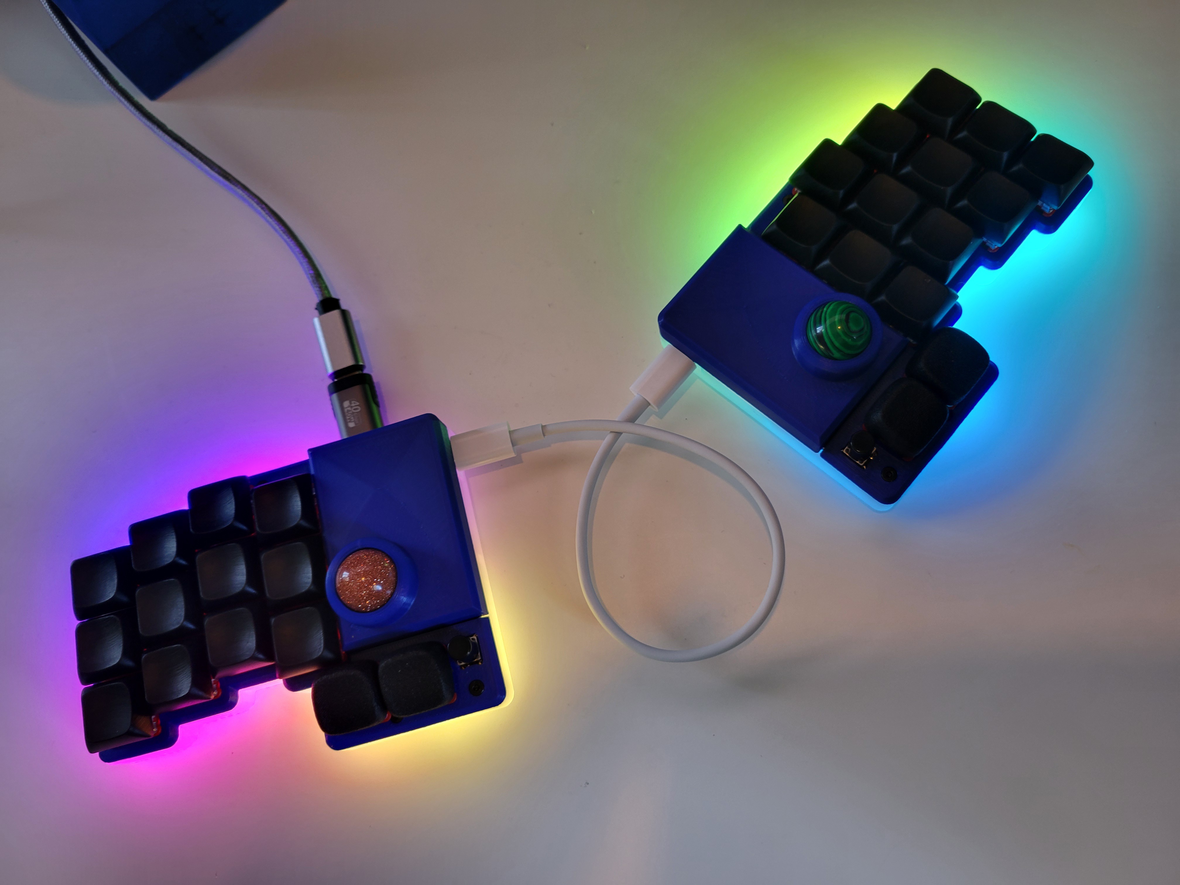
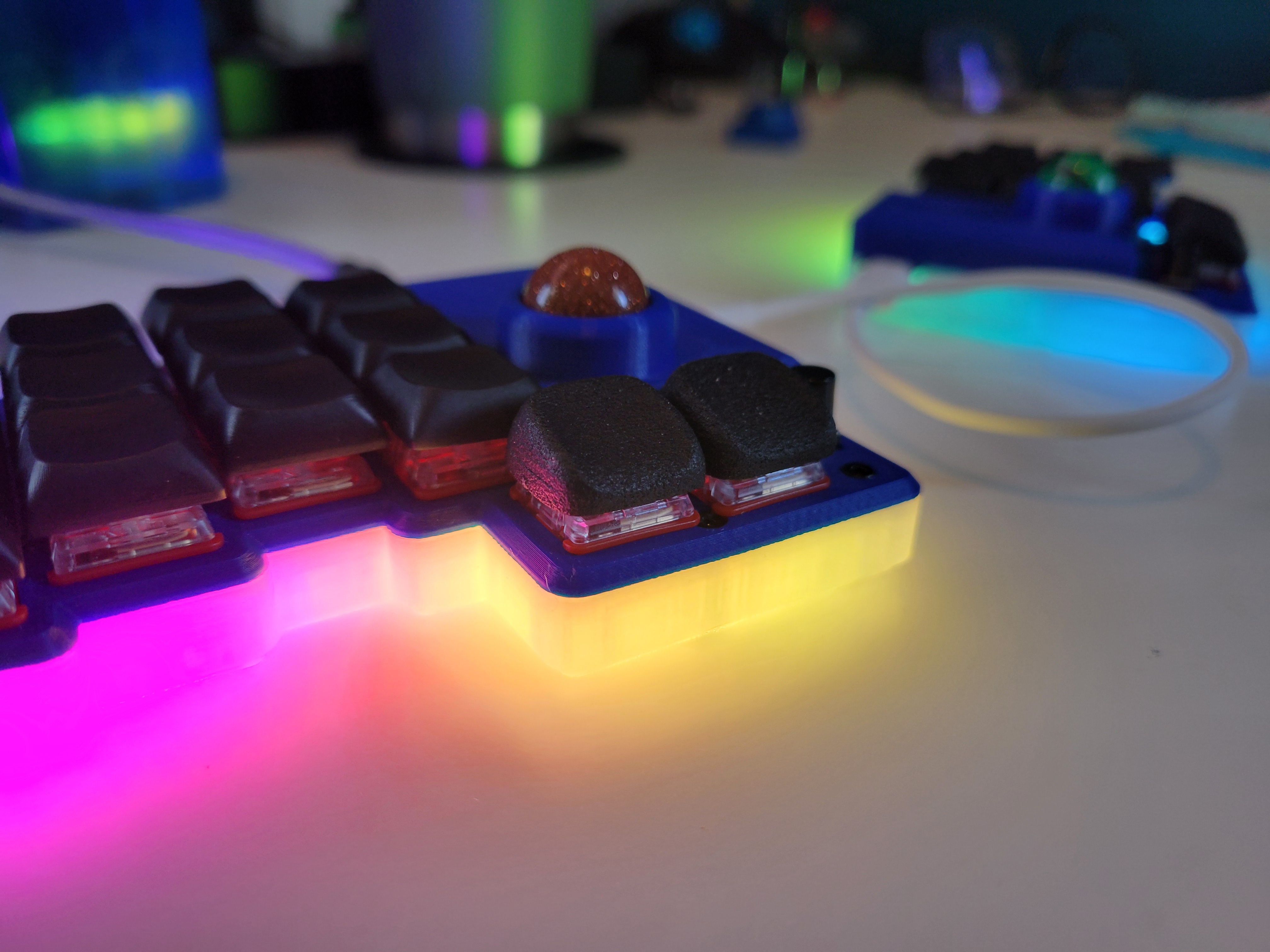
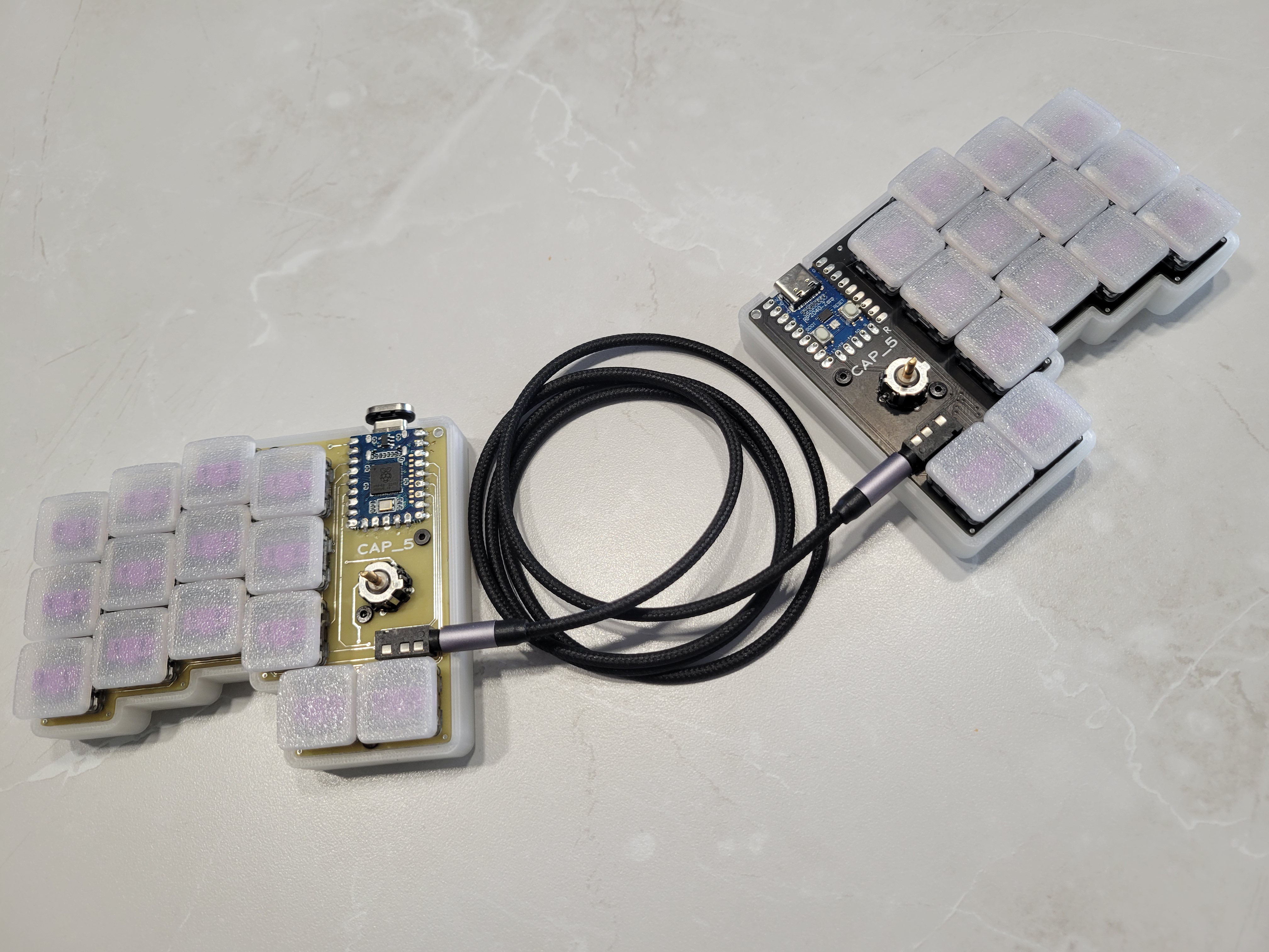
The Broken (stylized BR/KN) keyboard is named because...
I've always preferred small keebs and low switch counts. The idea for this keyboard was to design a small split that also incorporated two trackballs (can use one for pointing, one for scrolling!), and have some other goodies like LEDs and tact switches for occasional needs like macros or toggling the RGB.
The layout is a larger rendition of my MM20 (3 column) layout with the addition of side columms. I have no issues with my 20 key layout but it's a BIG change for users and having some keys like tab and backspace on dedicated keys can be convenient. Of course with custom firmware you are not locked into any specific layout. If you only want to combo 2 letters (24 non-thumb keys, 26 letters!), then that's totally fine.
The layout, MM28, leverages combos (the yellow letters shown below) for less-used letters, or where they "feel best". I performed some studies on letter frequency in the English language and most common bigrams and trigrams to determine the letter placement. It kind of started off as Colemak from what I recall, maybe it's actually really different, I forgets. P and B are weird, they both just barely made it to combos instead of their own letters even though I use them more often then I anticipated. They could have gone somewhere like the U and W keys but with the frequency I use them I wanted them on my index and middle finger instead of putting all that work on my ring finger.
The biggest thing with starting a layout like this is to accept the fact that you'll start off at like 5wpm but your brain will take over and it'll become second nature eventually just like any other layout. It's super fun and not making any lateral finger movements feels nice.
As noted in the Features, I chose a narrower keyswitch spacing and thus they require narrower keycaps. CFX keycaps are commercially available from Chosfox, or you can print your own, for which I've included files in the keycaps folder. They easily print upside down on an FDM printer, and I use a textured baseplate.
Contact with comments, questions, or if you build it!
| Qty | Value | Footprint | References |
|---|---|---|---|
| 34 | , , , , , , , , , , , , , , , +18 | ||
| 16 | 1uF | Capacitor_SMD:C_0603_1608Metric | C1, C2, C3, C4, C5, C6, C7, C8, C9, C10, C11, C12, C13, C14, C15, C16 |
| 15 | D | Diode_SMD:D_SOD-323 | D01, D02, D03, D04, D05, D06, D07, D08, D09, D10, D11, D12, D13, D14, D15 |
| 14 | SK6812MINI | miketronic_fplib:MB_SK6812_Mini | LED01, LED02, LED03, LED04, LED05, LED06, LED07, LED08, LED09, LED10, LED11, LED12, LED13, LED14 |
| 14 | SW | miketronic_fplib:MB_KailhChoc-1U_rev_17mm_oval | SW01, SW02, SW03, SW04, SW05, SW06, SW07, SW08, SW09, SW10, SW11, SW12, SW13, SW14 |
| 2 | 10k | Keebio-Parts:R_0805 | R2, R5 |
| 1 | 15k | Keebio-Parts:R_0805 | R3 |
| 1 | 39 | Keebio-Parts:R_0805 | R4 |
| 1 | 4.7uF | Capacitor_SMD:C_0603_1608Metric | C17 |
| 1 | 500 | Keebio-Parts:R_0805 | R1 |
| 1 | AP7335-WG-7 | Package_TO_SOT_SMD:SOT-23-5_HandSoldering | IC1 |
| 1 | PMW3360DM-T2QU | miketronic_fplib:MB_PMW3360 | U3 |
| 1 | SW | miketronic_fplib:MB_6x6_SW | SW15 |
| 1 | TRRS | miketronic_fplib:MB_TRRS-PJ-320A | U2 |
| 1 | USB_C | miketronic_fplib:MB_Molex-216990_USB_TYPE-C | J1 |
| 1 | rp2040-zero | miketronic_fplib:MB_rp2040-zero-001 | U1 |
The 105 most common of 125 parts.
It measures 102.5 × 72.6 mm and has 2 copper layers, 1.2 mm thick.
125 parts, built around the PMW3360DM-T2QU, RP2040-ZERO and SK6812MINI-E. The full list of its parts is on this page, with links to each part's symbol and footprint where PCBKit's library has them.
From the miketronic/brkn repository on GitHub, at the commit this page was made from: the board is pcb/left/BRKN_v1_LEFT.kicad_pcb and its schematic pcb/left/BRKN_v1_LEFT.kicad_sch. PCBKit opens the board in the browser, with nothing to install.
Its repository states no licence, so its author keeps all rights: ask miketronic before reusing the design.


cormoran/dya-keyboard
Pre-built QMK firmware is available in latest build's artifact section in this github actions.


