Skip to the content
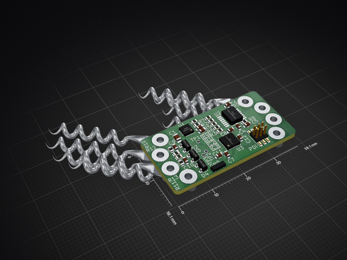
2 layers38.1 × 19.1 mmLED Relay, the printed circuit board in 3D

Motorcycle LED Relay replacement PCB.

Size
38.1 × 19.1 mm
Copper layers
2
Thickness
1.6 mm
Parts
45
Nets
50
Pads
144
Tracks, vias
125, 14
Pours
5
Routed
Yes
KiCad
KiCad 4
Created
19 Aug 2017
Updated
20 Aug 2017

Overview

LED Relay is an open-source printed circuit board by mikelawrence, from the mikelawrence/LED-Relay repository on GitHub, published under the MIT licence. It is a 2-layer board of 38.1 × 19.1 mm with 45 parts on 50 nets, routed with 125 tracks and 14 vias.

It is built around the ATXMEGA8E5-M4U, BTS7008-2EPA and LT3014IDD#PBF, with the BAT54S and SM15T33CA among its other parts. Its parts include 13 resistors, 12 capacitors, 9 connectors, 4 diodes and 3 ICs. It belongs with the home automation and IoT boards and the AVR (ATmega, ATtiny) boards of this library.

Main components

5

README

README.md

LED Relay Replacement PCB

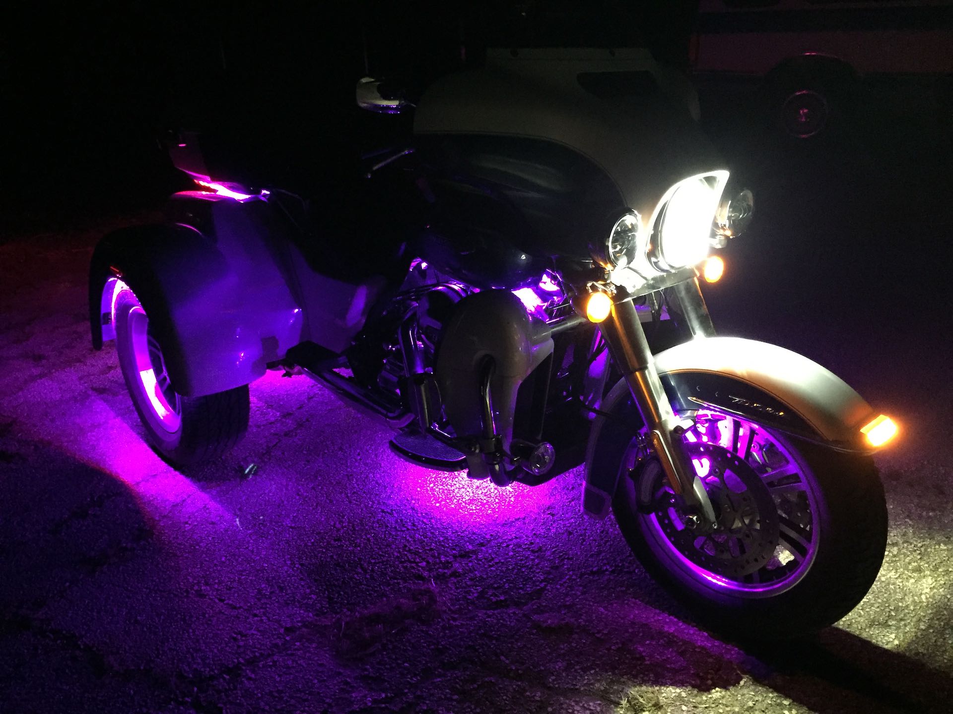
This board was designed to act as a relay for multi-color strip LED lighting on my wife's Harley Tri Glide. The Infineon BTS7008 Dual High-Side Switch provides up to 7.5A per channel. The software allows a quick on-off-on sequence that keeps the LEDs lit after the trike is turned off for a programmable delay time in minutes. In addition to the Stay ON sequence the board also allows programming the amount of time to delay time. Set main.c for instructions on how to issue Stay ON sequence.

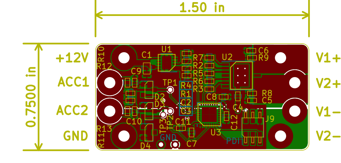
There are 4 inputs to the LED Relay board:

  • +12V - This should be connected through a fuse to the battery and should remain hot even when the trike is off. All power to the outputs comes from this wire.
  • ACC1 - This is +12V when the bike is turned on (ignition).
  • ACC2 - This is +12V when the LED lights should be on.
  • GND - Chassis and negative terminal of the battery. The current software turns both outputs on when both ACC1 and ACC2 are at +12V but this can easily be changed to two independent outputs each controlled by its own ACC input. When either ACC1 off the micro-controller enters a low power state waiting for ACC1 to go back to +12V. Note with my current setup ACC2 can never go to +12V without ACC1 also going to +12V.

Status and Testing

  • Rev 2.2 PCB has not been ordered or tested. Since there is only one simple change and my Rev 2.1 was modified to Rev 2.2 I feel confident Rev 2.2 is ready for use.
    • Added ACC1 connection to PD2 on micro-controller. Only PIN2 has full asynchronous edge detection needed for ACC1.
    • You can order parts from Mouser using this shared BOM. Note LT3014 is not available at Mouser you must get it somewhere else like Digikey.
    • You can order the PCB from OSH Park using this link to OSH Park.
  • Rev 2.1 PCB has been ordered from OSH Park, assembled, and tested.
    • Added R12 and R13.
    • Moved ACC connections on micro-controller.
    • Testing complete after modifying to Rev 2.2.
  • Rev 2.0 PCB.
    • Converted older design to KiCad.
    • Switched from low-side switch to dual high-side switch.
  • Rev 1.0 Existed as another design that was close.

Board Preview
Notes

  • The current usage is only one channel with a typical 4A LED load and maximum of 6A. I have not done any load testing to see how well the board operates with both channels going full bore. The High-Side Switch will shutdown to protect itself if it get too hot.
  • When ACC1 is off the XMega8E5 enters an ultra low power mode drawing about 1µA. Add that to the LT3014 linear regulator's quiescent current and this board has standby current of 8µA. In bench testing my first board used 7.8µA at room temperature. Keep in mind this current is likely to double or even triple at higher temperatures but for a motorcycle or car battery this standby current is excellent.
  • JP1 must be in place for circuit to work correctly. JP1 is a good scope ground point in testing.
  • Assembling the this PCB will require a reflow oven. If you don't have one Whizoo sells a nice kit to make your own.
  • PCB is designed in KiCad which is a great free EDA toolset.

Software

The microcontroller is a Atmel/Microchip XMega8E5. Software is written in C using the free Atmel Studio 7. I recommend the Atmel ICE to both debug and program the XMega. Especially since it already has a 50mil PDI connector to plug directly onto the LED Relay board.

Protection Against the Elements

When mounting on a motorcycle protection against the elements is crucial to longevity so the LED Relay board is thin enough to get 1" adhesive heat shrink on it. Once shrunk the board is well protected and the wires also get some strain relief.

Note I used several different sizes of adhesive heat shrink to get a watertight seal around the wires.
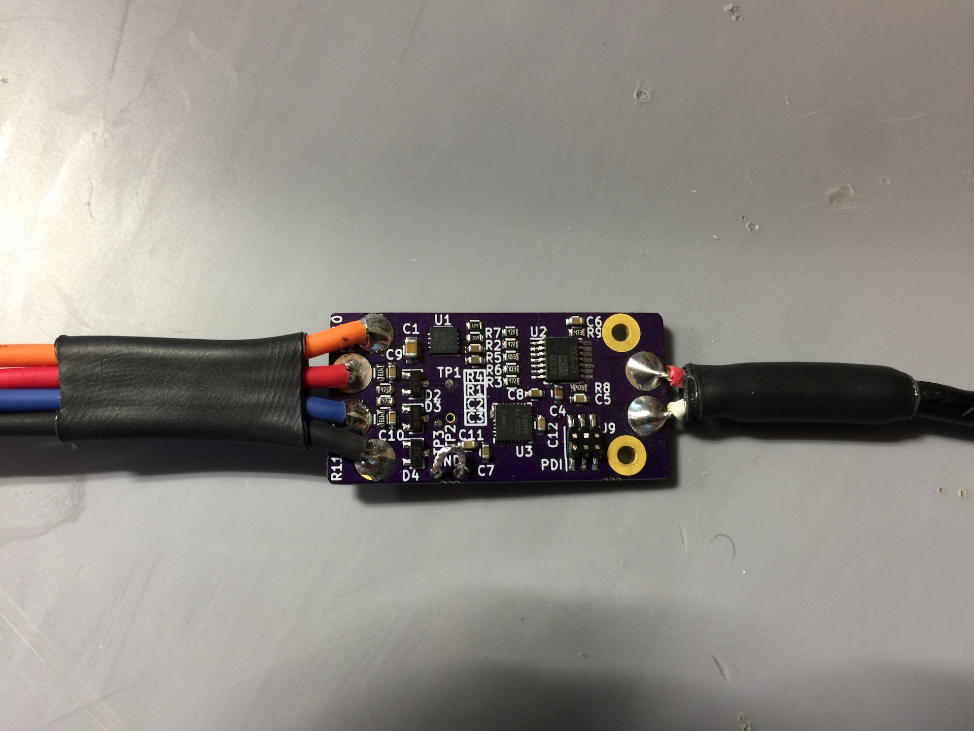
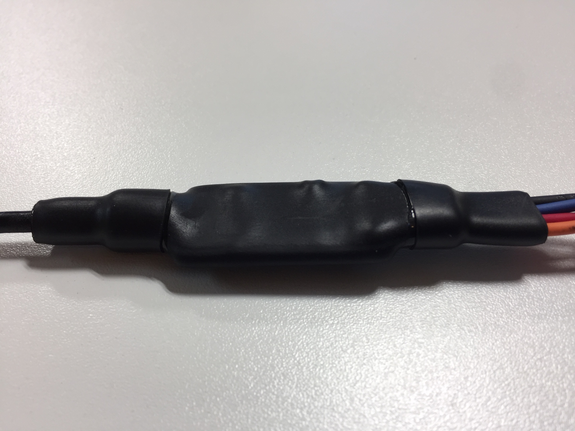
Final Result

Here is the obligatory end result picture!
Parts

45
QtyValueFootprintReferences
8TEST_1PWire_Pads:SolderWirePad_single_2mmDrillJ1, J2, J3, J4, J5, J6, J7, J8
610nFCapacitors_SMD:C_0603C5, C6, C9, C10, C11, C12
647kResistors_SMD:R_0603R8, R9, R10, R11, R12, R13
40.47uFCapacitors_SMD:C_0603C2, C3, C7, C8
3TEST_1PWire_Pads:SolderWirePad_single_0-8mmDrillTP1, TP2, TP3
210kResistors_SMD:R_0603R5, R6
24.7kResistors_SMD:R_0603R2, R3
2BAT54STO_SOT_Packages_SMD:SOT-23D2, D3
11.27MResistors_SMD:R_0603R4
11uFCapacitors_SMD:C_0805C1
12.15MResistors_SMD:R_0603R1
147Resistors_SMD:R_0603R7
168nFCapacitors_SMD:C_0603C4
1ATXMEGA8E5-M4UHousings_DFN_QFN:QFN-32-1EP_4x4mm_Pitch0.4mmU3
1BTS7008-2EPAHousings_SOIC_ML:Infineon_PG-TSDSO-14-22U2
1GNDWire_Connections_Bridges:WireConnection_0.80mmDrill_ThinPadJP1
1HeaderPin_Headers:Pin_Header_Straight_2x03_Pitch1.27mm_SMDJ9
1LT3014IDDHousings_DFN_QFN:DFN-8-1EP_3x3mm_Pitch0.5mmU1
1SM15T33CADiodes_SMD:D_SMC_HandsolderingD1
1ZRC330TO_SOT_Packages_SMD:SOT-23D4

Similar boards

  • 4 layers72.4 × 95.3 mmDingoPDM, the printed circuit board in 3D

    DingoPDM

    corygrant/dingoPDM

    Hardware - dingoPDM is an open source, affordable automotive PDM (Power Distribution Module). Pre-assembled and tested units are available or the design can be used to build a DIY version.

    156 parts128MIT
  • 4 layers135 × 82.5 mmProteus, the printed circuit board in 3D

    Proteus

    mck1117/proteus

    protean: able to do many different things; versatile.

    1,052 parts50
  • 2 layers66 × 51.5 mmWiFi Gate Controller, the printed circuit board in 3D

    WiFi Gate Controller

    mikelawrence/WiFi-Gate-Controller

    WiFi enabled Gate Controller Addon to US Automatic Gate Opener

    91 parts8MIT
  • 4 layers147.8 × 65 mmPrius gen2, the printed circuit board in 3D

    Prius gen2

    ksmola/PriusG2

    Inverter control board for Toyota Prius Gen 2 (XW20) inverter. Some of the schematics are based on Johannes Huebner's work found here. Running openinverter firmware.

    149 parts3
  • 2 layers88.8 × 52.3 mmMM36-Data Expansion, the printed circuit board in 3D

    MM36-Data Expansion

    KazanNinja/MM36-Data-Hub

    ESP32 based DAQ board. Fit with a 4 external 16bit 5V capable ADCs, 6-DOF IMU, and GPS breakout. Has two 5V > 3.3V & 12V > 3.3V voltage dividers

    84 parts1

Questions

How big is the LED Relay PCB?

It measures 38.1 × 19.1 mm and has 2 copper layers, 1.6 mm thick.

What parts does the LED Relay use?

45 parts, built around the ATXMEGA8E5-M4U, BTS7008-2EPA, LT3014IDD#PBF and BAT54S. The full list of its parts is on this page, with links to each part's symbol and footprint where PCBKit's library has them.

Where can I download the LED Relay KiCad files?

From the mikelawrence/LED-Relay repository on GitHub, at the commit this page was made from: the board is LED Relay.kicad_pcb. PCBKit opens the board in the browser, with nothing to install.

Can I use the LED Relay design in my own project?

Its repository publishes it under the MIT licence: you may reuse it on that licence's terms (keep the author's notice, and for a copyleft licence share your changes alike).