
2 layers113 × 62.2 mm
FullScope
tvlad1234/pillScopePlus
Oscilloscope based around the STM32F401 Black Pill and a color LCD screen
15 parts165Apache-2.0

 Mihnea-Jianu/asm_led_controller
The ASM LED Controller Board is an algorithmic state machine, designed to store and run a microprogram which controls the states of the 22 LEDs that make up the on-board, heart-shaped LED array.
Asm led controller is an open-source printed circuit board by Mihnea-Jianu, from the Mihnea-Jianu/asm_led_controller repository on GitHub. It is a 2-layer board of 199.5 × 92.1 mm with 67 parts on 90 nets, routed with 748 tracks and 118 vias.
It is built around the LM7805. Its parts include 24 resistors, 22 diodes, 6 ICs, 1 capacitor and 1 switch.
The ASM LED Controller Board is an algorithmic state machine, designed to store and run a microprogram which controls the states of the 22 LEDs that make up the on-board, heart-shaped LED array.
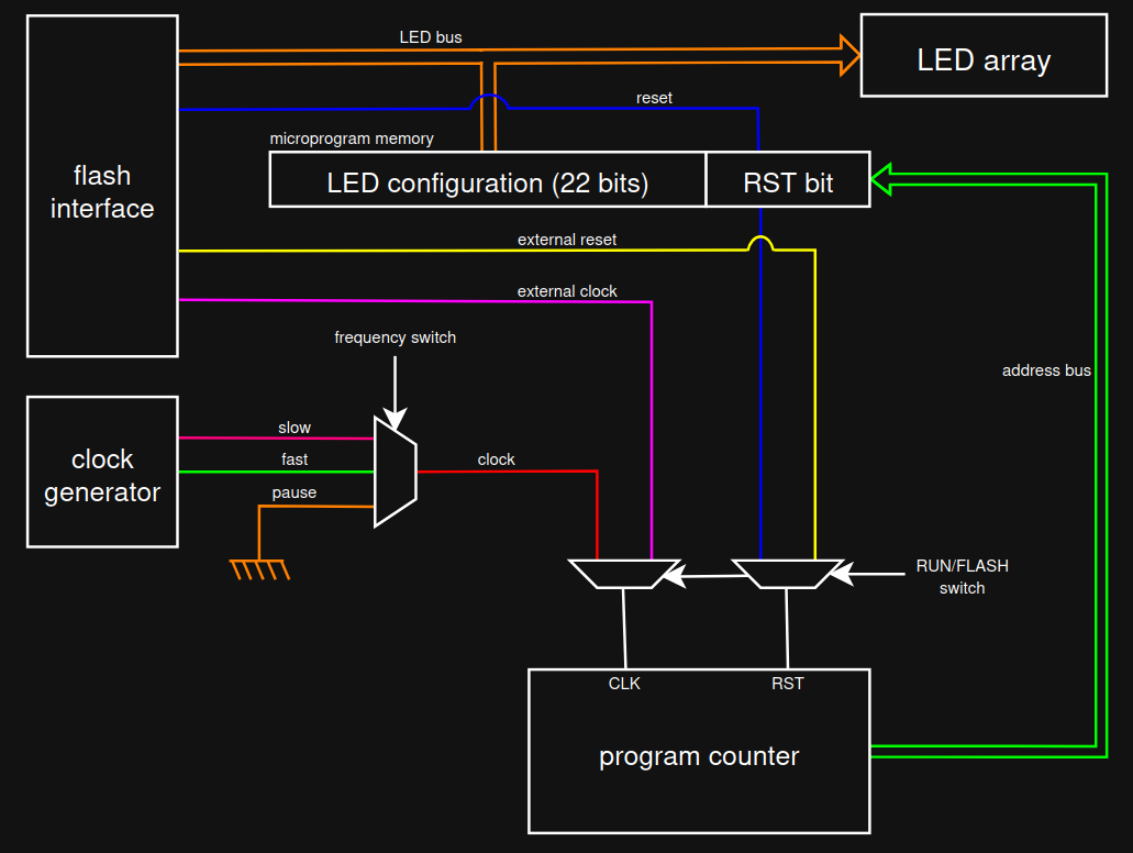
The clock generator is simply a CD4060BE binary counter, which is setup to use
its built-in oscillator with the RC setup.
From the frequencies generated at the pins of the chip, I have selected a
slow one [Q8] and a fast one [Q7], and hooked them up to a SP3T slide
switch, for clock speed selection. The third pole of the slide switch is
connected to GND, equivalent to a paused clock.
The output of this slide switch is the main clock of the circuit.
The program counter is another CD4060BE binary counter, whose outputs are used
to iterate through the addresses of the memory chips.
When in RUN mode
When in FLASH mode
The microprogram memory consists of 3 concatenated AS6C1008-55PCN SRAM chips.
Their addresses are 8 bits wide, so we have a total of 24 bits per address.
The current address of the memory chips is controlled by the program counter, and the outputs of the memory chips go directly to the LED array.
When in RUN mode
When in FLASH mode
To flash the device, you will need a development board that has 26 usable digital output pins, like the Arduino Mega.
The asm_led_flasher.ino sketch, under software/, is setup to use pins 22-47
of the Arduino Mega, which must be connected to the flash interface.
The flash interface consists of 26 digital pins:
| Pin | Arduino Mega Pin | Type | Role |
|---|---|---|---|
| L1 - L22 | 26 - 47 | data pin | load LED configurations into memory |
| RST | 25 | data pin | load reset bit into memory |
| XWE | 24 | control pin | write the values at the data pins into memory |
| XRST | 23 | control pin | reset the current address of the memory |
| XCLK | 22 | control pin | increment the current address of the memory |
Set the on-board switches to the following configuration:
| Switch | Position |
|---|---|
| ON/OFF | ON |
| ON/OFF LED | ON |
| RUN/FLASH | FLASH |
| FREQUENCY | PAUSE |
Once everything is setup, connect the Arduino Mega to your computer, and upload
the software/asm_led_flasher.ino sketch to it.
When the builtin LED lights up, you have 10 seconds to flip the top RUN/FLASH switch back to RUN.
When the builtin LED lights up again, you can flip the bottom RUN/FLASH switch back to RUN, disconnect the flash interface from the Arduino Mega, and unpause the clock.
hardware/
software/
| Qty | Value | Footprint | References |
|---|---|---|---|
| 22 | 220 | Resistor_THT:R_Axial_DIN0207_L6.3mm_D2.5mm_P7.62mm_Horizontal | R1, R2, R3, R10, R11, R12, R13, R14, R15, R16, R17, R18, R19, R20, R21, R22 +6 |
| 22 | LED | LED_THT:LED_D5.0mm | D1, D2, D3, D10, D11, D12, D13, D14, D15, D16, D17, D18, D19, D20, D21, D22 +6 |
| 2 | Battery | BH-18650-PC:BAT_BH-18650-PC | BT1, BT2 |
| 1 | 0.01uF | Capacitor_THT:C_Disc_D3.8mm_W2.6mm_P2.50mm | C1 |
| 1 | 100K | Resistor_THT:R_Axial_DIN0207_L6.3mm_D2.5mm_P7.62mm_Horizontal | R24 |
| 1 | 10K | Resistor_THT:R_Axial_DIN0207_L6.3mm_D2.5mm_P7.62mm_Horizontal | R23 |
| 1 | 4060 Frequency Counter | CD4060BE:DIP794W45P254L1969H508Q16 | U4 |
| 1 | 4060 Program Counter | CD4060BE:DIP794W45P254L1969H508Q16 | U5 |
| 1 | AS6C1008-55PCN Program Memory 1 | AS6C1008-55PCN:DIP1524W45P254L4191H419Q32 | U1 |
| 1 | AS6C1008-55PCN Program Memory 2 | AS6C1008-55PCN:DIP1524W45P254L4191H419Q32 | U2 |
| 1 | AS6C1008-55PCN Program Memory 3 | AS6C1008-55PCN:DIP1524W45P254L4191H419Q32 | U3 |
| 1 | Flash Interface | Connector_PinHeader_2.54mm:PinHeader_2x13_P2.54mm_Vertical | FLASH INTERFACE |
| 1 | Frequency Switch | OS103011MS8QP1:OS102011MS8QP1 | FREQUENCY |
| 1 | LM7805 | LM7805:TO220 | U6 |
| 1 | On/Off Switch ASM | Button_Switch_THT:SW_Slide_SPDT_Straight_CK_OS102011MS2Q | ON/OFF |
| 1 | On/Off Switch LED | JS202011CQN:JS202011CQN | ON/OFF LED |
| 1 | Run/Flash Switch 1 | JS202011CQN:JS202011CQN | SW3 |
| 1 | Run/Flash Switch 2 | JS202011CQN:JS202011CQN | RUN/FLASH |
The 61 most common of 67 parts.
tvlad1234/pillScopePlus
Oscilloscope based around the STM32F401 Black Pill and a color LCD screen

PhysicsDptAngers/polyUAnalog
Open source, analog and polyphonic synthesizer

thebiguno/microcontroller-projects
A home for a bunch of microcontroller projects which don't warrant their own repos.

wntrblm/Big_Honking_Button
A simple Eurorack sampler and performance module in a silly package.


tebl/C64-Modulator-Replacement
A simple modulator replacement for Commodore 64s with "longboards", complements my Lumafix version as well adding an audio connector for second SID.


It measures 199.5 × 92.1 mm and has 2 copper layers, 1.6 mm thick.
67 parts, built around the LM7805. The full list of its parts is on this page, with links to each part's symbol and footprint where PCBKit's library has them.
From the Mihnea-Jianu/asm_led_controller repository on GitHub, at the commit this page was made from: the board is hardware/asm_led_controller.kicad_pcb and its schematic hardware/asm_led_controller.kicad_sch. PCBKit opens the board in the browser, with nothing to install.
Its repository states no licence, so its author keeps all rights: ask Mihnea-Jianu before reusing the design.