2 layers52.3 × 10.5 mm
StackLink
gusmanb/logicanalyzer
24 channel, 100Msps logic analyzer hardware and software
29 parts5.1kGPL-3.0

 Mickael235/topobot
Holonomic Mecanum robot for automated topographic measurements using STM32, Raspberry Pi, custom electronics and a supervision interface.
Connectique Cop Ensim Elec is an open-source printed circuit board by Mickael235, from the Mickael235/topobot repository on GitHub. It is a 2-layer board of 135 × 117.5 mm with 29 parts on 115 nets, routed with 430 tracks and 6 vias.
Its parts include 10 resistors, 4 connectors and 1 diode. It belongs with the robots and motor control boards of this library.
Autonomous holonomic robot for automated topographic surface-flatness inspection
ENSIM × ESGT · 4th-year Engineering Project · 2025–2026
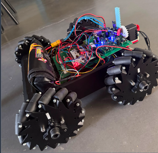
STM32 F446RE · Raspberry Pi · Mecanum · Encoders · AX-12 · XBee · KiCad · Python · C
TopoBot is a holonomic mobile robot developed to automate the repetitive part of a topographic surface-flatness survey.
In a conventional workflow, an operator manually moves a reflector from point to point while another operator operates the total station. TopoBot was designed to replace this manual point-by-point displacement with a configurable robotic mission:
The project combines robotics, embedded control, electronics, radio communication, software supervision and topographic instrumentation in one integrated prototype.
Project status: the main hardware/software building blocks were integrated and validated on the prototype. Final industrial-grade accuracy, complete odometry/total-station fusion and a full production flatness campaign remain future work.
| Item | Implementation |
|---|---|
| Mobile base | Lynxmotion A4WD3 with 4 Mecanum wheels |
| Real-time controller | STM32 Nucleo F446RE |
| High-level computer | Raspberry Pi 4 |
| Motor power stage | 2 × Sabertooth motor drivers |
| Motion feedback | 4 incremental wheel encoders |
| Prism mechanism | AX-12 servomotor + rack-and-pinion mechanism |
| Station communication | XBee S2C radio link + serial / RS232 interface |
| Supervision | TopoBot Manager on tablet / browser |
| Data storage | SQLite on Raspberry Pi |
| Export | CSV |
| Real-time control loop | 100 Hz |
| Project budget | €500 |
| Actual project cost | €318.26 |
| Team | 4 engineering students |
The functional specification targeted a configurable survey grid up to 50 m × 50 m, with a nominal 0.5 m grid spacing and a 40 mm spherical reflector.
This is a design requirement, not a claim that the complete 50 × 50 m campaign was validated during the project.
Manual surface inspection with a total station is repetitive: the reflector must be moved and positioned at many points, while measurements are triggered and recorded.
TopoBot aims to transform this workflow into a supervised autonomous sequence.
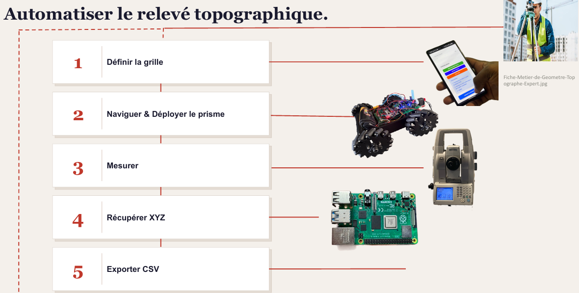
Define grid
    ?
Generate waypoints
    ?
Navigate to waypoint
    ?
Stabilize robot
    ?
Deploy prism
    ?
Trigger total-station measurement
    ?
Recover XYZ / angles / distance
    ?
Retract prism
    ?
Store point in SQLite
    ?
Send progress to TopoBot Manager
    ?
Next waypoint
    ?
Export mission data to CSV
The trajectory is generated as a boustrophedon path: the direction alternates from one grid row to the next to reduce unnecessary travel.
The robot must interact with the surveyor, the surface, the total station, the energy source and the safety environment.

The main service functions are:
| Ref. | Function | Main requirement |
|---|---|---|
| FP1 | Move and orient the reflector | Configurable grid, 40 mm reflector |
| FC1 | Communicate with the total station | XBee S2C radio link, commands + coordinates |
| FC2 | Provide configuration and monitoring | Tablet / smartphone interface |
| FC3 | Provide energy autonomy | Rechargeable battery |
| FC4 | Operate in an indoor environment | Flat surface, future obstacle/drop detection |
| FC5 | Respect safety/environment constraints | Emergency stop and safe integration |
TopoBot is not a single-controller robot. It uses a distributed architecture in which the computational responsibilities are separated.
flowchart LR
    UI["Tablet / Browser<br><b>TopoBot Manager</b>"]
    PI["Raspberry Pi 4<br><b>Mission supervisor / middleware</b>"]
    MCU["STM32 F446RE<br><b>Real-time motion controller</b>"]

    UI <-->|Network / Web interface| PI
PI <-->|Binary serial protocol| MCUThe operator uses TopoBot Manager to:
The Raspberry Pi acts as the high-level computer. It is responsible for:
The STM32 F446RE performs the time-critical functions:
This separation keeps real-time control local to the microcontroller while the Raspberry Pi focuses on supervision and mission logic.
flowchart TD
    APP["TopoBot Manager<br>Tablet / PC"]
    RPI["Raspberry Pi 4<br>Mission supervisor"]
    STM["STM32 F446RE<br>100 Hz real-time control"]
    PCB["Custom control board<br>KiCad / JLCPCB"]

    ENC["4 wheel encoders"]
    SAB["2 × Sabertooth<br>motor drivers"]
    MOT["4 DC motors<br>4 Mecanum wheels"]
    AX["AX-12 servo<br>Prism deployment"]
    ESTOP["Emergency stop"]
    BATT["Battery monitoring"]

    XB1["XBee S2C #1"]
    XB2["XBee S2C #2"]
    RS232["MAX3232 / RS232"]
    TOPCON["Robotic total station"]

    APP <-->|Supervision| RPI
    RPI <-->|Binary serial protocol| STM

    ENC --> STM
    STM --> PCB
    PCB --> SAB
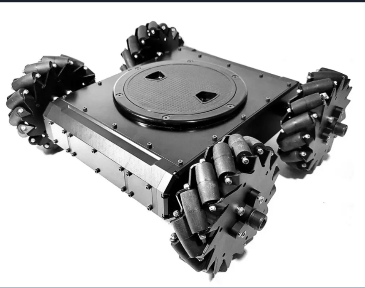
The Lynxmotion A4WD3 base uses four Mecanum wheels, allowing longitudinal, lateral and rotational motion.
| Motion | Front Left | Front Right | Rear Left | Rear Right |
|---|---|---|---|---|
| Forward | + | + | + | + |
| Backward | - | - | - | - |
| Left translation | - | + | + | - |
| Right translation | + | - | - | + |
| Left rotation | - | + | - | + |
| Right rotation | + | - | + | - |
The current survey mission mainly uses translations with a constant orientation. Nevertheless, the command interface preserves the full pose parameter:
MOVE_TO(x, y, theta)This keeps the architecture extensible toward complete pose control.
Early tests demonstrated the expected Mecanum motion but also revealed parasitic rotation during straight translations due to wheel/motor asymmetry.
This led to:
The embedded firmware is organised around several modules:
STM32 firmware
+-- Mecanum kinematics
+-- Encoder acquisition
+-- Odometry
+-- PID / motion control
+-- Robot state machine
+-- Raspberry Pi protocol
+-- AX-12 prism control
+-- Safety / robot configuration
The repository contains the STM32 project in:
firmware/stm32/The controller uses the following main states:
stateDiagram-v2
    [*] --> IDLE
    IDLE --> MOVING: MOVE_TO
    MOVING --> SETTLING: target reached
    SETTLING --> DONE: position confirmed
    DONE --> IDLE
    MOVING --> ERROR: fault
    SETTLING --> ERROR: fault
    IDLE --> ESTOP: emergency stop
    MOVING --> ESTOP: emergency stop
    SETTLING --> ESTOP: emergency stop
Main states:
IDLE — waiting for a command;MOVING — moving toward the target;SETTLING — stabilizing around the waypoint;DONE — waypoint reached and confirmed;ERROR / ESTOP — error or emergency stop.The Raspberry Pi only sends the next waypoint after receiving a DONE status.
The Raspberry Pi does not directly control the motors.
It sends high-level commands to the STM32 using a lightweight binary protocol:
[ START | CMD | LEN | PAYLOAD | CRC ]The project uses a simple XOR-based CRC over the command, payload length and payload.
| Command | Role |
|---|---|
MOVE_TO | Reach target pose (x, y, ?) |
STOP | Immediate robot stop |
RESET_ODOM | Reset odometry before a mission |
GET_STATUS | Read position, speed and current state |
DEPLOY_PRISM | Deploy the topographic prism |
RETRACT_PRISM | Retract the prism |
The STM32 returns status frames such as:
STATUS
DONE
ERROR
These messages allow the Raspberry Pi backend to orchestrate the mission without interfering with the real-time control loop.
The mission is generated from:
Zone width  = X
Zone length = Y
Grid step   = p
The backend generates the waypoint set:
(xi, yj)
xi = i × p
yj = j × p
and orders them in a boustrophedon trajectory.
1. RESET_ODOM
   +- Reset the robot local reference before starting.

2. Generate waypoints
   +- Build the complete boustrophedon measurement grid.

3. For each waypoint:
   +- Send MOVE_TO(x, y, ?)
   +- Wait for STM32 STATUS updates
   +- Continue only after DONE

4. If measurement mode is enabled:
   +- DEPLOY_PRISM
   +- Trigger / request Topcon measurement
   +- Recover measurement values
   +- RETRACT_PRISM

5. Save measurement
   +- Timestamp + local coordinates + station data ? SQLite

6. Notify front-end
   +- Mission progress and current data ? WebSocket

7. Continue with next waypoint
A station-independent test mode was also kept. In this mode the robot can execute the grid with simulated measurement values, making it possible to debug navigation without depending on the topographic instrument.
The topographic reflector is mounted on a rack-and-pinion mechanism actuated by an AX-12 servomotor.
The mechanism is responsible for:
RETRACTED
    ?
DEPLOY_PRISM
    ?
Prism positioned for measurement
    ?
Total-station acquisition
    ?
RETRACT_PRISM
    ?
Robot resumes navigation
This sequence is synchronized with waypoint validation so that measurements are not requested while the robot is still moving.
A custom control board was designed in KiCad, manufactured by JLCPCB, assembled and integrated into the robot.
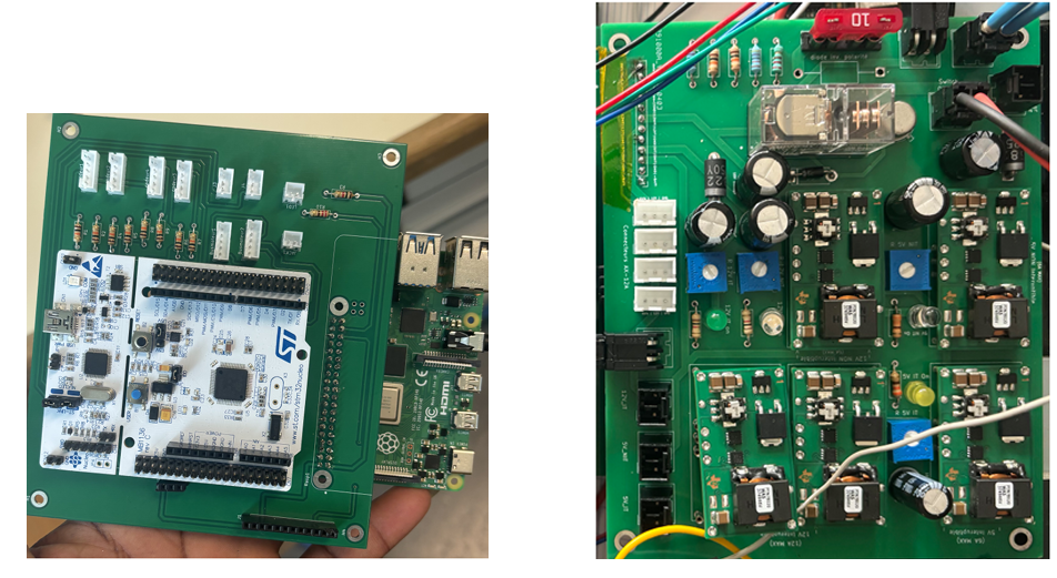
The control electronics centralize:
The pre-existing power board was reused, while the control board was redesigned specifically for this project.
The KiCad project and Gerber manufacturing files are available under:
hardware/control-board/
+-- kicad/
+-- manufacturing/
+-- gerbers/TopoBot communicates with the robotic total station through a dedicated radio/serial chain.
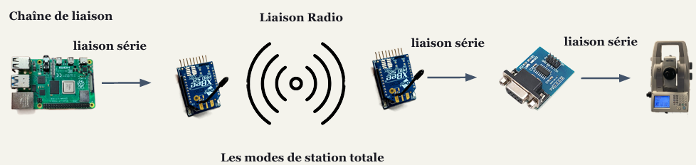
Raspberry Pi
    ¦
    ¦ USB / UART serial
    ?
XBee S2C #1
    ))) RADIO (((
XBee S2C #2
    ¦
    ¦ Serial
    ?
MAX3232 / RS232 converter
    ¦
    ¦ RS232
    ?
Robotic total station| Parameter | Configuration |
|---|---|
| Baud rate | 9600 |
| Data bits | 8 |
| Parity | None |
| Stop bits | 1 |
| Flow control | None |
| Channel | C / 0x0C |
| PAN ID | B332 |
The modules were configured using Digi XCTU.
The project explored three main station modes:
std)High-precision fixed measurement using fine targeting.
trk)Fast tracking / targeting of a moving reflector.
Continuous acquisition of distances and horizontal/vertical angles.
The automated acquisition sequence uses the station together with the robot prism workflow to recover the current measured point and feed it back into the mission data.
Known limitation: the XBee radio link showed intermittent reliability problems during field testing. Improving the radio layer is one of the main future-work items.
TopoBot Manager is the supervision interface designed for tablet use.
Its purpose is to hide the complexity of the robot, STM32, Raspberry Pi and total station behind a guided workflow.
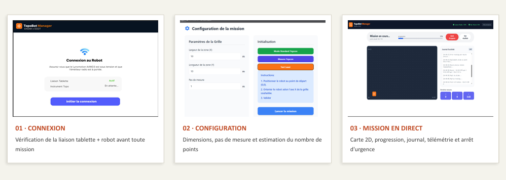
The application follows three main user stages.
Before a mission starts, the interface verifies that the robot and measurement system are reachable.
Typical checks include:
The operator cannot proceed until the system is ready.
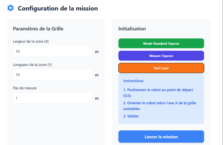
The operator defines:
X;Y;p;The backend uses these values to determine the grid and generate the mission waypoints.
During execution, the interface displays:
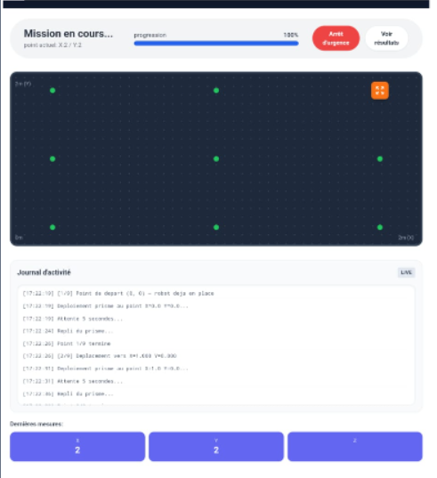
The complete information flow can be summarized as:
+--------------------------------------+
¦ Tablet / Browser                    ¦
¦ TopoBot Manager                     ¦
¦ - configuration                     ¦
¦ - live map                          ¦
¦ - progress                          ¦
¦ - logs                              ¦
¦ - emergency stop                    ¦
+--------------------------------------+
                    ¦ HTTP / WebSocket
                    ?
+--------------------------------------+
¦ Raspberry Pi                        ¦
¦ Middleware / Mission Supervisor     ¦
¦ - route generation                  ¦
¦ - waypoint orchestration            ¦
¦ - SQLite                            ¦
¦ - CSV export                        ¦
¦ - total-station communication       ¦
+--------------------------------------+
                ¦               ¦
        Binary serial           ¦ XBee / serial
                ¦               ¦
? ?Each measurement point is stored locally on the Raspberry Pi.
The project uses SQLite for mission data and exposes the final dataset through CSV export.
| Field | Meaning |
|---|---|
ID | Unique measurement-point identifier |
HEURE | Acquisition timestamp |
X, Y | Local planar coordinates |
HZ | Horizontal station angle |
V | Vertical station angle |
DIST | Radial distance measured by the station |
The mission data lifecycle is:
Connection
    ?
Geometry configuration
    ?
Survey supervision
    ?
SQLite storage
    ?
CSV export
The CSV format was chosen to keep the results directly usable in spreadsheets and topographic post-processing tools.
The project was developed using progressive integration and physical tests.
MOVE_TO commands;| Subsystem | Status |
|---|---|
| Mecanum basic motion | ? Validated |
| STM32 real-time architecture | ? Implemented |
| Encoder feedback / odometry | ? Integrated |
| Raspberry Pi ? STM32 protocol | ? Implemented |
| High-level waypoint mission logic | ? Implemented |
| AX-12 prism deployment | ? Integrated and validated |
| Custom control PCB | ? Designed, manufactured and assembled |
| TopoBot Manager | ? Functional |
| Total-station communication modes | ? Exercised |
| XBee field robustness | ?? Functional but unreliable in some tests |
| Closed-loop tuning | ?? Requires finer adjustment |
| Odometry + total-station fusion | ?? Future work |
| Complete production flatness campaign | ?? Still to be finalized |
The goal of this repository is to present the real engineering state of the prototype, including both validated subsystems and remaining technical limitations.
The first physical tests revealed unwanted rotation during straight movement.
Probable causes included:
Encoder feedback and closed-loop control were introduced to improve trajectory stability.
Wheel odometry accumulates errors when the wheels slip or the ground is irregular.
A future version should fuse:
Wheel odometry
      +
High-precision total-station coordinates
      ?
Corrected robot localizationThe XBee solution proved useful for prototyping but showed intermittent signal losses.
A more robust professional radio solution would be preferable for field deployment.
The prototype contains a significant amount of point-to-point wiring. A future revision should use:
Obstacle/drop sensors were planned in the architecture but were not fully operational in the final prototype.
This was a four-person team project with distinct technical work packages.
My contribution focused primarily on control, kinematics and motion validation, including:
The complete project also includes major contributions from the other team members in supervision/UI, XBee communication and electronics/PCB integration.
| Team member | Main work package |
|---|---|
| Bénéwindé Kontiebo | Project management · Supervision · HMI |
| Aymane Fariss | Communication · XBee / total-station link |
| Arsène Nguenang Youkap | Electronics · PCB · hardware integration |
| Michael Essomba | Control · kinematics · AX-12 prism mechanism |
The project was managed using an agile-inspired workflow with regular synchronization and milestone reviews.
The project operated under a €500 budget.
| Metric | Value |
|---|---|
| Available budget | €500 |
| Actual project cost | €318.26 |
| Remaining budget | €181.74 |
| Budget utilization | ~64% |
A significant part of the platform was reused from previous cohorts:
New spending focused mainly on the Raspberry Pi, STM32 boards, control electronics, passive components and PCB manufacturing.
topobot/
+-- README.md
+-- .gitignore
¦
+-- assets/
¦   +-- images/
¦   ¦   +-- hero/
¦   ¦   ¦   +-- topobot-hero.png
¦   ¦   ¦
¦   ¦   +-- diagrams/
¦   ¦   ¦   +-- functional-architecture.png
¦   ¦   ¦   +-- mission-workflow.png
¦   ¦   ¦   +-- xbee-communication-chain.png
¦   ¦   ¦
¦   ¦   +-- hardware/
¦   ¦   ¦   +-- robot-platform.png
¦   ¦   ¦   +-- control-and-power-board.png
¦   ¦   ¦   +-- total-station.png
¦   ¦   ¦   +-- robot-cad-render.png
¦   ¦   ¦
¦   ¦   +-- ui/
¦   ¦       +-- topobot-manager-flow.png
¦   ¦       +-- mission-config.png
¦ ¦ +-- mission-live-dashboard.pngGenerated build files, local databases, virtual environments, IDE temporary files and dependency directories are intentionally excluded from version control.
C · STM32 F446RE · STM32CubeIDE · HAL
Mecanum kinematics · Encoders · Odometry · PID · State machine · AX-12
Python · Raspberry Pi · SQLite · WebSocket
UART · Serial · XBee S2C · RS232
KiCad · PCB design · Gerber · JLCPCB
Robotic total station · Topographic prism · Tracking
Git · GitHub · Hardware testing · Technical documentation
A short demonstration of the physical prototype is available here:
Detailed engineering documentation is available in docs/.
Main documents:
The next engineering priorities are:
PID tuning
Reduce oscillations and trajectory error.
Odometry calibration
Improve the estimation of x, y and ?.
Odometry / total-station sensor fusion
Correct wheel-slip drift using high-precision station feedback.
Radio reliability
Replace or harden the XBee communication chain for field use.
Active navigation safety
Integrate obstacle, drop and stair detection.
Wiring redesign
Reduce point-to-point wiring and use locking connectors.
Large-grid validation
Validate longer missions and repeated surveys under realistic conditions.
Full flatness campaign
Complete the end-to-end autonomous survey and compare results against a reference workflow.
TopoBot evolved from an inherited mechanical platform into an integrated robotic prototype combining:
The project demonstrates the feasibility of automating a topographic surface-inspection workflow while also identifying the engineering work still required to reach robust field deployment.
ENSIM × ESGT — Le Mans University
Academic year: 2025–2026
| Qty | Value | Footprint | References |
|---|---|---|---|
| 8 | 10k | Resistor_THT:R_Axial_DIN0207_L6.3mm_D2.5mm_P10.16mm_Horizontal | R1, R2, R4, R5, R6, R7, R8, R9 |
| 4 | MountingHole | MountingHole:MountingHole_3.2mm_M3_DIN965_Pad | H1, H2, H3, H4 |
| 2 | Roue codeuse droite | Connector_JST:JST_PH_B5B-PH-K_1x05_P2.00mm_Vertical | codeur1, codeur3 |
| 2 | Roue codeuse gauche | Connector_JST:JST_PH_B5B-PH-K_1x05_P2.00mm_Vertical | codeur2, codeur4 |
| 2 | pont H | Connector_JST:JST_PH_B5B-PH-K_1x05_P2.00mm_Vertical | Busmoteur1, Busmoteur2 |
| 1 | 1k | Resistor_THT:R_Axial_DIN0207_L6.3mm_D2.5mm_P10.16mm_Horizontal | R3 |
| 1 | 220 | Resistor_THT:R_Axial_DIN0207_L6.3mm_D2.5mm_P10.16mm_Horizontal | R10 |
| 1 | Conn_01x12_Pin | Connector_PinHeader_2.54mm:PinHeader_1x12_P2.54mm_Vertical | J1 |
| 1 | Connector JACK | Connector_JST:JST_PH_B2B-PH-K_1x02_P2.00mm_Vertical | JACK1 |
| 1 | Connector LED | Connector_JST:JST_PH_B2B-PH-K_1x02_P2.00mm_Vertical | LED1 |
| 1 | Jumper | Connector_PinHeader_2.54mm:PinHeader_1x03_P2.54mm_Vertical | J2 |
| 1 | NUCLEO-F446RE | ENSIMelec empreintes utiles:MODULE_NUCLEO-F446RE gauche | gauche1 |
| 1 | NUCLEO-F446RE | ENSIMelec empreintes utiles:MODULE_NUCLEO-F446RE droite | droite1 |
| 1 | RaspberryPi | ENSIMelec empreintes utiles:MODULE_RASPBERRY_PI_4B_4GB | Rasp1 |
| 1 | Sabertooth1 | Connector_JST:JST_PH_B3B-PH-K_1x03_P2.00mm_Vertical | J3 |
| 1 | Sabertooth2 | Connector_JST:JST_PH_B3B-PH-K_1x03_P2.00mm_Vertical | J4 |
gusmanb/logicanalyzer
24 channel, 100Msps logic analyzer hardware and software

VoronDesign/Voron-Hardware
Cool Hardware designed by the Voron Design group

hoglet67/RGBtoHDMI
Bare-metal Raspberry Pi project that provides pixel-perfect sampling of Retro Computer RGB/YUV video and conversion to HDMI

hackclub/OnBoard
💡 Join 1,000 teenagers and make your first PCB with a $100 grant!

OLIMEX/DIY-LAPTOP
Do It Yourself Open Source Hardware and Software Modular Hacker's Friendly Laptop

UtilitechAS/amsreader-firmware
ESP8266 and ESP32 compatible firmware to read, interpret and publish data to MQTT from smart electrical meters, both DLMS and DSMR is supported


It measures 135 × 117.5 mm and has 2 copper layers, 1.6 mm thick.
29 parts. The full list of its parts is on this page, with links to each part's symbol and footprint where PCBKit's library has them.
From the Mickael235/topobot repository on GitHub, at the commit this page was made from: the board is hardware/control-board/Kicad/connectique_Cop_Ensim_Elec.kicad_pcb and its schematic hardware/control-board/Kicad/connectique_Cop_Ensim_Elec.kicad_sch. PCBKit opens the board in the browser, with nothing to install.
Its repository states no licence, so its author keeps all rights: ask Mickael235 before reusing the design.