2 layers103 × 30.5 mm
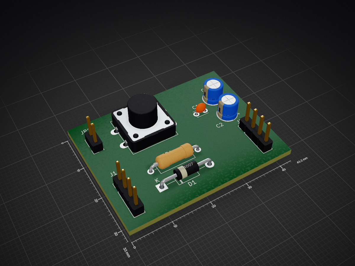
 mgoblin/STC-programmator2
Programmator for STC MCU (clone of Intel 8085 microcontroller)
STC15 programmator is an open-source printed circuit board by mgoblin, from the mgoblin/STC-programmator repository on GitHub, published under the CC0-1.0 licence. It is a 2-layer board of 43.2 × 33 mm with 9 parts on 8 nets, routed with 34 tracks and 0 vias.
Its parts include 3 capacitors, 2 connectors, 1 resistor, 1 diode and 1 switch. It belongs with the 8051 (CH55x, STC, AT89) boards of this library.
This repo contains kicad electrical scheme, pcb design and description of STC programmator.
STC is a family of microcontrollers with 8051 architecture.
The electrical scheme and PCB design are a Kicad files.
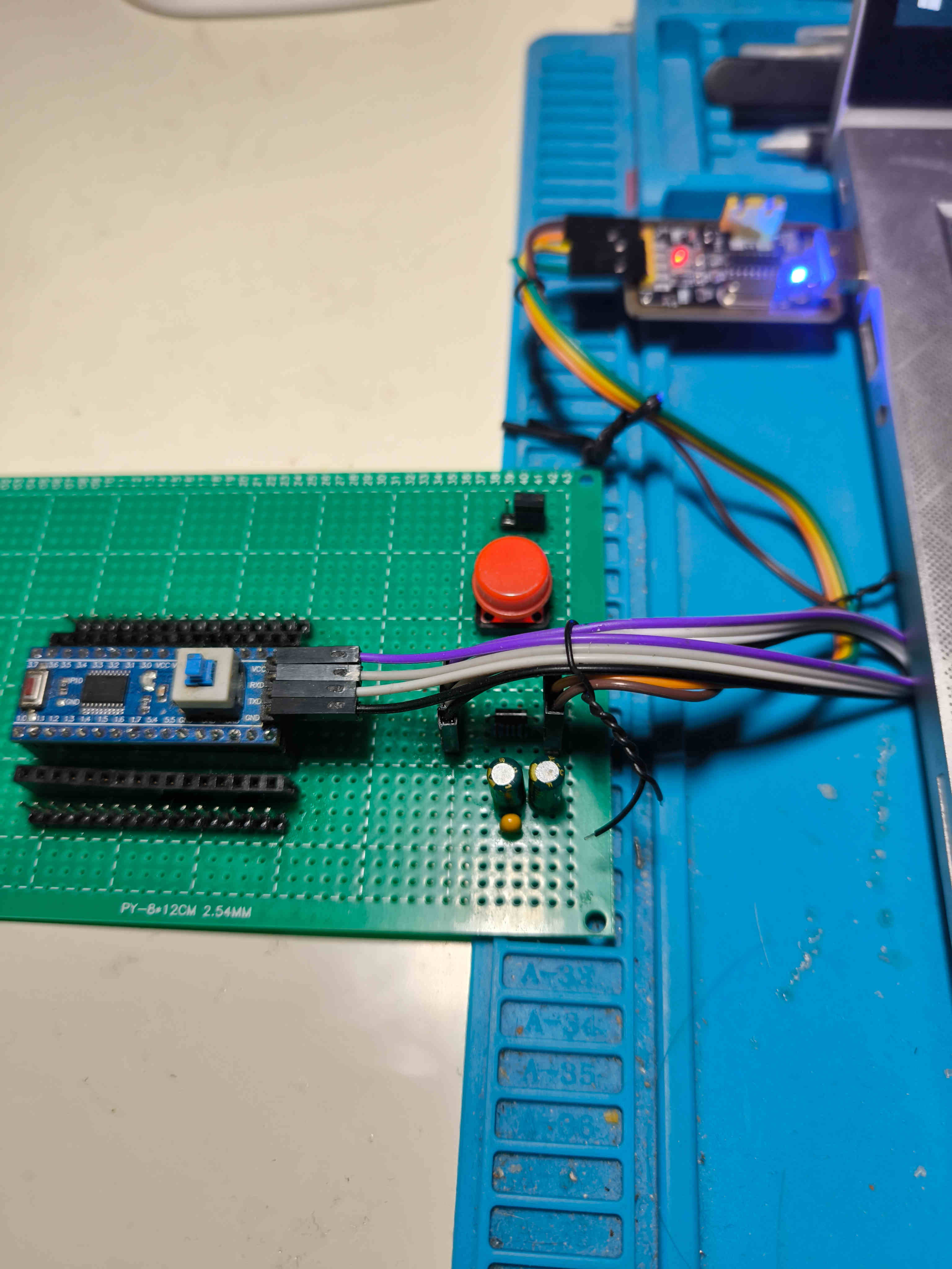
Programmator used with USB-2-TTL adapter.
CHG340g is a popular USB-2-TTL adapter.
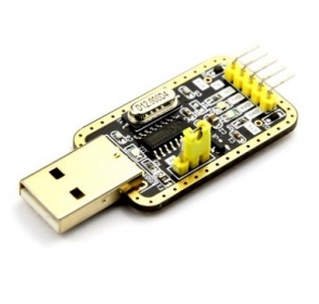
CHG340g should be connected to PC USB port and programmator is placed between CGH340g and STC MCU.
J1 for USB adapter
J2 for MCU
J2 +5V pin should be connected to MCU +5V pin.
J2 GND pin should be connected to MCU GND pin.
J2 TxD pin should be connected to MCU TxD pin.
J2 RxD pin should be connected to MCU RxD pin.
Jumper J1 is opened.
Inside programmator USB TxD is routed to MCU RxD and USB RxD is routed to MCU TxD pin.
[Plaformio] (https://platformio.org/) is a popular embedded software development IDE based on Visual Studio Code.
Platfromio use stcgal to upload firmware.
Jumper J1 should be opened before uploading start.
Connect USB adapter with programmator (see How to connect programmator section). JP1 jumper should be opened.
Connect programmator to MCU pins. Developer boards and many PCB designs have dedicated pins.
Run Platfromio and open your STC project with source code that will be compiled to firmware.
Connect USB adapter to PC.
In Platfromio start upload. The most popular way to do this is press upload button
Platformio open terminal panel and output upload status as a messages to it
Waiting for "Cycling power: done" message. Uploading process waiting.
Cycling power: done
Press and hold the SW1 button on the programmer until the download process is complete.
Uploading proccess completes with messages
Finishing write: done
Setting options: done
Target UID:
Disconnected!
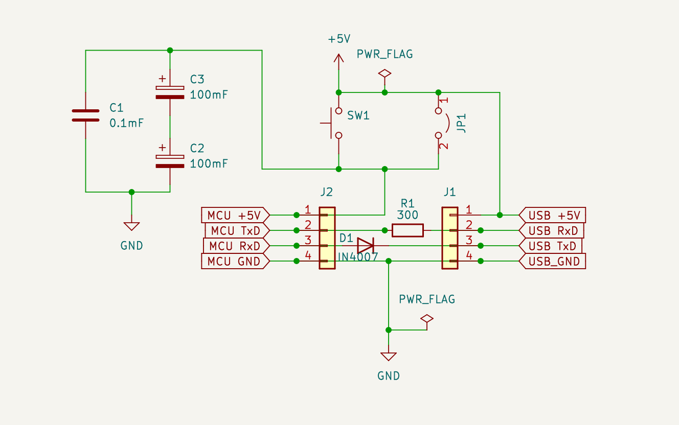
Scheme contains two important parts: TxD-RxD part and VCC part.
The principle of connection between MCU and USB adapter is RxD <-> TxD. R1 and D1 are used to eliminate parasitic power supply through the pins to the microcontroller.
The MCU is powered via USB-2-TTL adapter. MCU GND connect to USB adapter GND. USB adapter +5V connected to button SW1 and jumper JP1.
If the jumper JP1 is shorted, the microcontroller runs the loaded firmware and cannot be programmed. In firmware download mode, the jumper is open and power is supplied only when the SW1 button is pressed and held.
Capacitors C1-C3 debounce of the SW1 button. In the classic programmator scheme only one 47mF polaraized capacitor is placed. But i have only 100mF capasitors and connect it in a chain to get 50mF capacity.
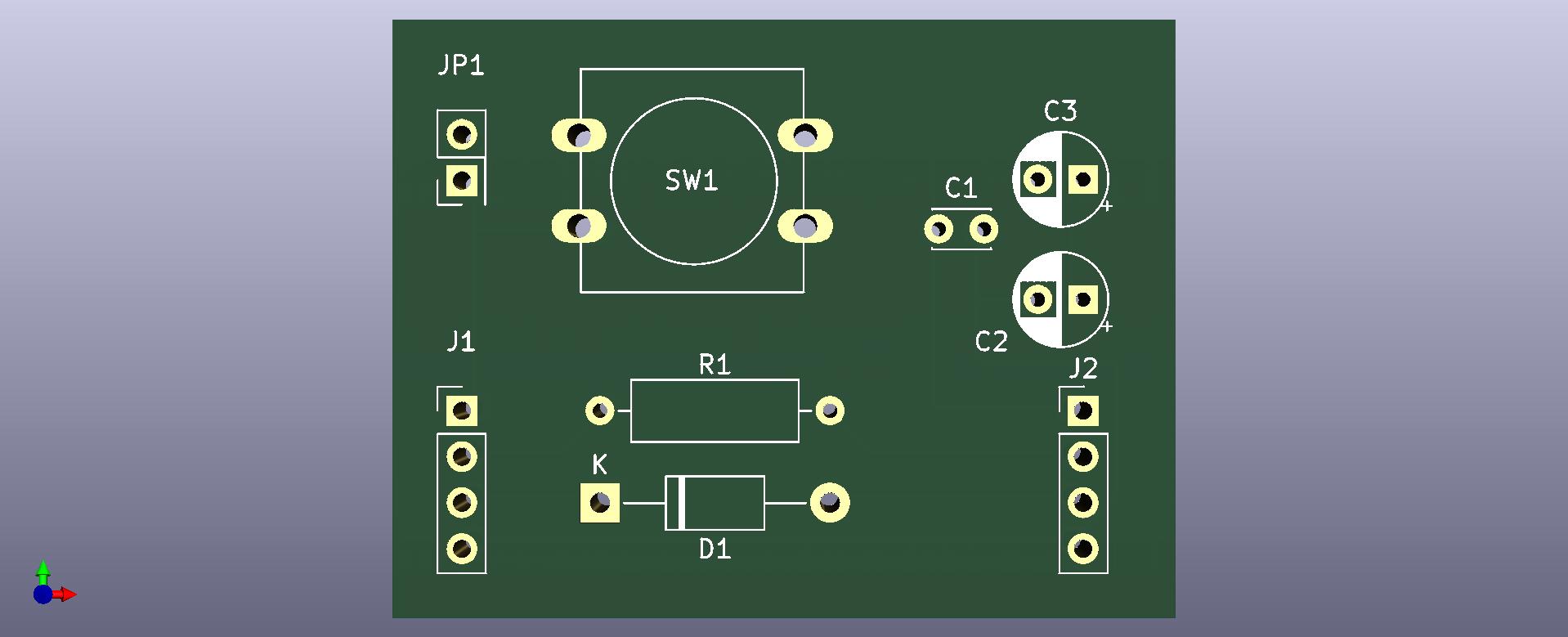
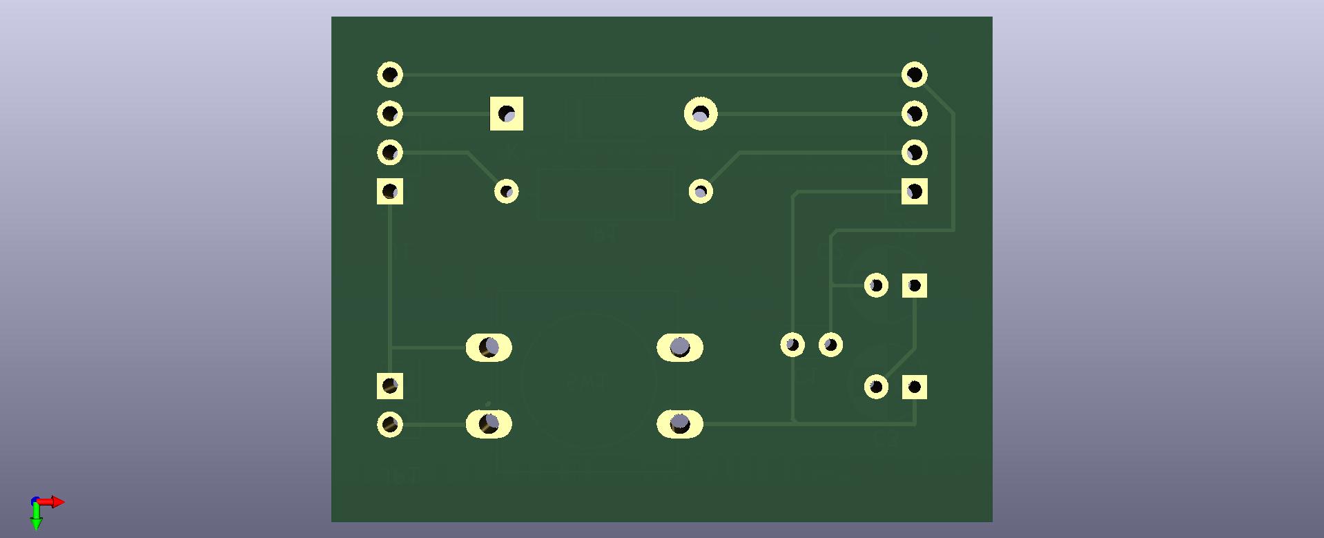
You can upload firmware to STC MCU with USB-To-TTL adapter only.
For this way disconnect GND wire from MCU and start firware upload. When stcgal out will be "Cycling power: done" connect GND from adapter to MCU.
| Qty | Value | Footprint | References |
|---|---|---|---|
| 2 | 100mF | Capacitor_THT:CP_Radial_D5.0mm_P2.50mm | C2, C3 |
| 2 | Conn_01x04 | Connector_PinHeader_2.54mm:PinHeader_1x04_P2.54mm_Vertical | J1, J2 |
| 1 | 0.1mF | Capacitor_THT:C_Disc_D3.0mm_W2.0mm_P2.50mm | C1 |
| 1 | 300 | Resistor_THT:R_Axial_DIN0309_L9.0mm_D3.2mm_P12.70mm_Horizontal | R1 |
| 1 | IN4007 | Diode_THT:D_DO-41_SOD81_P12.70mm_Horizontal | D1 |
| 1 | Jumper_2_Open | Connector_PinHeader_2.54mm:PinHeader_2x01_P2.54mm_Vertical | JP1 |
| 1 | SW_Push | Button_Switch_THT:SW_PUSH-12mm | SW1 |
It measures 43.2 × 33 mm and has 2 copper layers, 1.6 mm thick.
9 parts. The full list of its parts is on this page, with links to each part's symbol and footprint where PCBKit's library has them.
From the mgoblin/STC-programmator repository on GitHub, at the commit this page was made from: the board is STC15_programmator.kicad_pcb and its schematic STC15_programmator.kicad_sch. PCBKit opens the board in the browser, with nothing to install.
Its repository publishes it under the CC0-1.0 licence: you may reuse it on that licence's terms (keep the author's notice, and for a copyleft licence share your changes alike).


FrameworkComputer/ExpansionCards
Reference designs and documentation to create Expansion Cards for the Framework Laptop

VoronDesign/Voron-Hardware
Cool Hardware designed by the Voron Design group

hackclub/OnBoard
💡 Join 1,000 teenagers and make your first PCB with a $100 grant!


adamws/kicad-kbplacer
KiCad plugin for automatic keyboard's key placement and routing