4 layers53.2 × 53.2 mm
Smart lcc
magnusnordlander/smart-lcc
A smarter LCC for the Lelit Bianca V2, with Wi-Fi and stuff.
38 parts54

 measurify/example-soccer
This thesis project aims to develop a complete system for collecting and data classification in the sport of football, specifically for autonomous recognition of shooting, passing and stopping.
EdgeMeter is an open-source printed circuit board by measurify, from the measurify/example-soccer repository on GitHub. It is a 2-layer board of 48.5 × 26 mm with 23 parts on 46 nets, routed with 204 tracks and 16 vias.
It is built around the TLV61220DBV, ABX00027 and B82422A1472K100, with the JS202011SCQN and PMEG6020ER among its other parts. Its parts include 8 resistors, 5 capacitors, 5 ICs, 3 diodes and 1 switch.


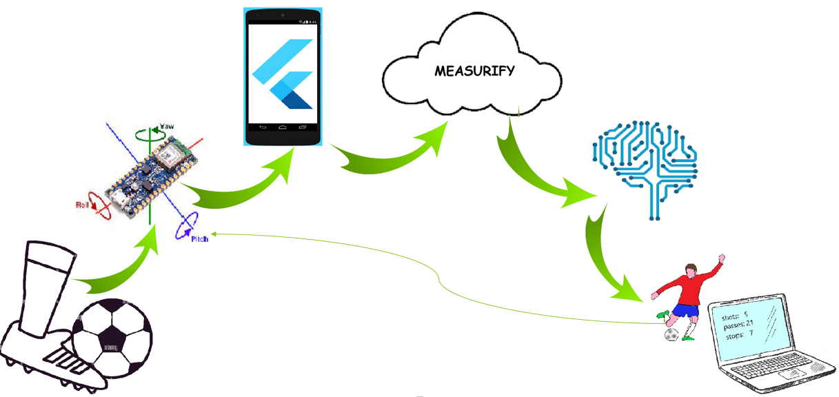
This thesis project aims to develop a complete system for collecting and data classification in the sport of football, specifically for autonomous recognition of shooting, passing and stopping. An Arduino Nano BLE Sense mounted on a shin guard connects via bluetooth to a mobile device application programmed with flutter. This application receives data relating to the board's IMU and sends it in turn to a cloud via Measurify with the addition of tags that identify the type of movement being recorded. These information constitutes the dataset needed to train a machine learning model. At the end of this training, the model is capable of autonomously recognizing the three movements above mentioned.
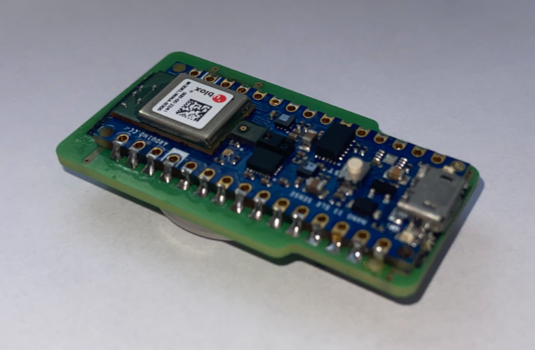
The board used is a Arduino Nano BLE Sense
The necessary code è:
Connect the Arduino via cable connection to the computer, selecting from the Arduino IDE menu Serial Port your Arduino and the cable to which it is connected (it should appear among the possible choices as COM-).
Search and install (if they are not already) in the Manage Libraries section the libraries included in the first part of the script.
At this point, load the script with the button at the top right. Once the upload is finished, you can log out the Arduino from the computer. Thanks to the custom battery mounted on it, it will be able to work without the need for cables.
Now switch to the flutter application: on VSCode load the flutter code and connect a mobile device via cable to run the app on it.Warning: to make it work you will first have to activate developer mode on your device settings and enable the "allow debugging" option. Once these precautions have been implemented, you can load the code by selecting run and then run without debugging selecting your device from the banner that opens centrally above the code among those available. Loading will take a few minutes. Once completed (you can disconnect the device from the computer).
The app interface will automatically appear in full screen with the page for scanning nearby Bluetooth devices. Turn on the Arduino and Measurify-Meter, the ID of your board, will appear on the device screen. Select it and the second screen for configuring the connection will open. Connect the Arduino to the device and you are ready to harvest the data. In the movement collection screen, select the tags relating to the movement you want to record from the drop-down menus and enter a label for the measurement name, then select the IMU option. Now press start and the Arduino will start send the data to your device. When you are done with the collection, press stop and send and if the data has arrived correctly to the cloud the message "data sent correctly" will appear at the bottom of the screen. once you have trained the model with the data sent to the cloud, you can proceed with testing it. To do this, reconnect the Arduino to the computer and load the trained model.
Now record the testing hits the same way you recorded the hits for the dataset. The output of the Arduino will show you its predictions of the movements. In this way you can discover how accurate the model is.
| Qty | Value | Footprint | References |
|---|---|---|---|
| 2 | 10kohm | Resistor_SMD:R_0805_2012Metric_Pad1.20x1.40mm_HandSolder | R2, R6 |
| 2 | 10uF | Capacitor_Tantalum_SMD:CP_EIA-3216-18_Kemet-A_Pad1.58x1.35mm_HandSolder | C1, C2 |
| 2 | 4,7uF | Capacitor_Tantalum_SMD:CP_EIA-3216-18_Kemet-A_Pad1.58x1.35mm_HandSolder | C3, C4 |
| 2 | LED | LED_SMD:LED_0805_2012Metric_Pad1.15x1.40mm_HandSolder | D1, D3 |
| 1 | 100nF | Capacitor_SMD:C_0805_2012Metric_Pad1.18x1.45mm_HandSolder | C5 |
| 1 | 110K | Resistor_SMD:R_0805_2012Metric_Pad1.20x1.40mm_HandSolder | R3 |
| 1 | 1K | Resistor_SMD:R_0805_2012Metric_Pad1.20x1.40mm_HandSolder | R5 |
| 1 | 1M | Resistor_SMD:R_0805_2012Metric_Pad1.20x1.40mm_HandSolder | R1 |
| 1 | 1kohm | Resistor_SMD:R_0805_2012Metric_Pad1.20x1.40mm_HandSolder | R4 |
| 1 | 2kohm | Resistor_SMD:R_0805_2012Metric_Pad1.20x1.40mm_HandSolder | R8 |
| 1 | 3006 | lib:3006 | U1 |
| 1 | 470ohm | Resistor_SMD:R_0805_2012Metric_Pad1.20x1.40mm_HandSolder | R7 |
| 1 | 74LVC1G04Z-7 | Package_TO_SOT_SMD:SOT-353_SC-70-5_Handsoldering | IC2 |
| 1 | ABX00027 | lib:ABX00027 | U2 |
| 1 | B82422A1472K100 | lib:INDC3225X210N | L1 |
| 1 | JS202011SCQN | lib:JS202011SCQN | S1 |
| 1 | MCP73831-2ATI_OT | lib:SOT95P270X145-5N | IC3 |
| 1 | PMEG6020ER | Diode_SMD:D_SOD-128 | D2 |
| 1 | TLV61220 | lib:SOT95P280X145-6N | IC1 |
It measures 48.5 × 26 mm and has 2 copper layers, 1.6 mm thick.
23 parts, built around the TLV61220DBV, ABX00027, B82422A1472K100 and JS202011SCQN. The full list of its parts is on this page, with links to each part's symbol and footprint where PCBKit's library has them.
From the measurify/example-soccer repository on GitHub, at the commit this page was made from: the board is edge/edge-meter-master/hardware/EdgeMeter.kicad_pcb and its schematic edge/edge-meter-master/hardware/EdgeMeter.kicad_sch. PCBKit opens the board in the browser, with nothing to install.
Its repository states no licence, so its author keeps all rights: ask measurify before reusing the design.
magnusnordlander/smart-lcc
A smarter LCC for the Lelit Bianca V2, with Wi-Fi and stuff.


louisonmalinge/Projet-Velux
Dans ce Git, vous trouverez les fichiers ayant permis de réaliser le projet Velux, avec ses différentes versions.

peterisza/mobilecg
MobilECG II is an open source clinical grade Holter ECG. For more information, please visit http://mobilecg.hu.

