2 layers57 × 55.2 mm
LogicAnalyzer
gusmanb/logicanalyzer
24 channel, 100Msps logic analyzer hardware and software
10 parts5.1kGPL-3.0

 mbed92/robotic-manipulator1
Robotic manipulator
Robotic manipulator is an open-source printed circuit board by mbed92, from the mbed92/robotic-manipulator repository on GitHub, published under the MIT licence. It is a 2-layer board with 10 parts on 38 nets, routed with 78 tracks and 0 vias.
Its parts include 7 connectors, 1 capacitor and 1 switch. It belongs with the AVR (ATmega, ATtiny) boards of this library.
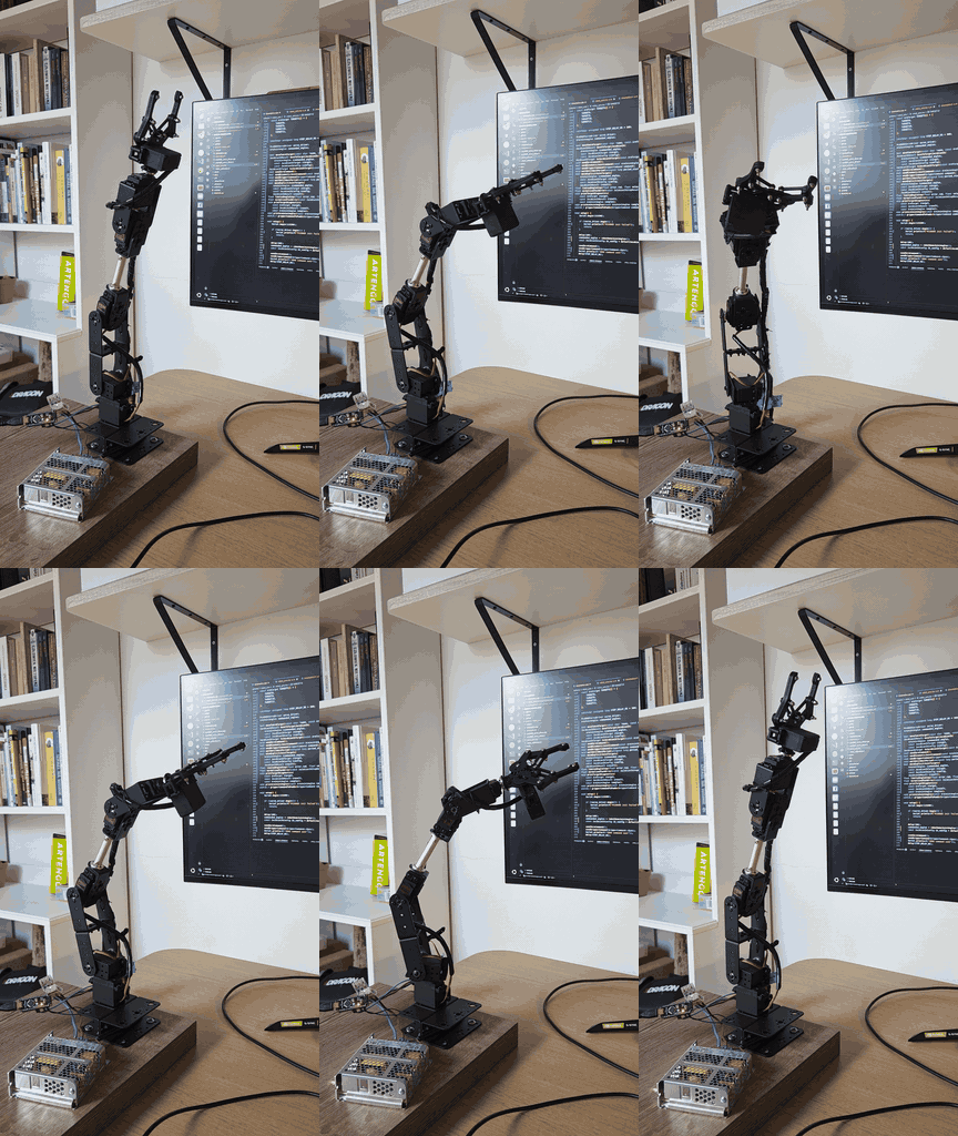
A small robotic manipulator project controlled by an Arduino Nano through a PCA9685 servo driver. The repository contains Arduino firmware, the kinematic model, angle-to-PWM mapping, calibration constants, and PCB files. This is my side project, and I had a lot of fun working on it.
arduino/robot_arm/robot_arm.ino - main firmware sketch.arduino/robot_arm/kinematics.h / kinematics.cpp - forward kinematics, Jacobian IK step generation, and angle-to-PWM conversion.arduino/robot_arm/robot_calibration.h - servo channels, joint limits, HOME pose, and arm dimensions.arduino/robot_arm/pca9685_servo_driver.h / pca9685_servo_driver.cpp - PCA9685 driver wrapper.docs/bom.md - V1 prototype bill of materials.docs/lessons-learned.md - practical notes from calibration, IK debugging, and wiring.docs/TODO.md - project task notes and planned improvements.pcb/ - KiCad PCB project.The firmware assumes:
J0-J5, where J0-J4 are part of the kinematic model
and J5 is the gripper.The mechanical design and servo selection are based on material from Elektroweb.
Joint indices map to PCA9685 channels defined in
arduino/robot_arm/robot_calibration.h.
The manipulator is modeled as an arm with five kinematic joints:
J0 - base rotation around the vertical axis,J1-J3 - pitch joints forming the planar arm chain,J4 - local wrist/TCP rotation, independent of TCP position in the current model,J5 - gripper, controlled outside the kinematic model.TCP position is represented by the TcpPose structure:
reach_x_m - reach in the arm plane, in meters,reach_z_m - TCP height, in meters,yaw_rad - base rotation, in radians.Angle convention:
J1-J3 = 0 means that the arm segments point vertically upward,sin(angle),cos(angle),J0 controls the yaw of the whole arm,J4 does not change the TCP position reported by forward kinematics.Arm dimensions are stored in JOINT_OFFSETS:
L1 - vertical distance from base J0 to shoulder J1,L2-L4 - planar arm segment lengths,L5 - offset from the last link to the TCP.forwardKinematics() takes J0-J4 joint angles and returns a TcpPose.
The computation accumulates consecutive pitch angles:
pitch_1 = J1,pitch_2 = J1 + J2,pitch_3 = J1 + J2 + J3.The TCP reach and height are then computed from link lengths L2-L5.
In the current model, L4 and L5 have the same direction as the final pitch
J1 + J2 + J3.
The firmware uses an open-loop Jacobian IK trajectory generator based on the commanded joint state:
computeJacobianIkStep() is a pure numerical function. It computes one IK
step from the current commanded joint angles, target, and configuration. It
does not write PWM, wait, or access hardware.moveToTargetJacobianIk() in robot_arm.ino is the blocking hardware-facing
trajectory generator. It calls the step function, checks limits, converts the
next angles to PWM, writes the PCA9685 channels, waits until the next control
period, and updates the commanded joint state.J0, J3, and J4 axes toward their targets with the same fixed period and
velocity limits. This gives the local Jacobian solve the intended J3
geometry instead of starting from the vertical HOME singularity.The IK task is:
J3,J4.Only the coupled planar subproblem [reach, height, J3] <-> [J1, J2, J3]
uses damped least squares. J0 yaw and J4 are handled as direct proportional
controllers with the same joint velocity and joint limit handling as the planar
joints. Task rows have explicit weights so meter and radian errors are scaled
before the DLS solve.
The solver limits joint velocity by computing a global alpha scale. If any
requested joint velocity exceeds its limit, the whole q_dot vector is scaled
by the smallest required ratio. For example, if a joint requests 3 rad/s and
the limit is 2 rad/s, the whole command is scaled by 2/3. The current
default joint velocity limit is 0.5 rad/s for each kinematic joint.
The default motion configuration uses a 20 ms control period and allows up to
500 iterations per target. With the default period this gives a maximum of
about 10 s for one blocking target move before the target is reported as not
converged.
Joint limits also shrink the global step before failing the motion. A target is reported as blocked only when the step scale is effectively exhausted while the task error is still too large. The blocking motion loop also detects lack of progress so the robot does not spend several seconds making tiny noisy motions near an unreachable target.
Damped least squares does not remove physical singularities. Near a singular configuration, some TCP directions are still not achievable by the mechanism. DLS only prevents the numerical controller from asking for unbounded joint velocities.
Because J3 is an explicit task requirement and also part of the reach/height
kinematics, it restricts the reachable workspace. Some points that are
geometrically reachable with free J3 may not be reachable when a specific
J3 value is required.
Possible error statuses include:
OutOfReach - the target did not converge within the configured iteration budget,JointLimitViolation - the current or computed command violates joint limits,JointLimitBlocked - joint limits prevent useful progress toward the target,NoProgress - the solver stopped reducing the normalized task error,InvalidInput - the input contains invalid values, such as NaN or infinity.The current firmware executes a fixed pick-and-place demo sequence during startup:
TARGET1 through TARGET11 in robot_arm.ino define target TcpPose
values, explicit J3, explicit J4, and gripper state.setup() initializes the PCA9685, sends the arm to ZERO/HOME, and opens
the gripper.loop() stays idle.This is not closed-loop feedback from joint sensors. It is an open-loop trajectory generator that assumes the commanded state is a reasonable estimate of the servo state. Every new target and transition should still be tested carefully on hardware.
J3 and J4 are explicit task inputs; J3 constrains reachable TCP
positions.jointAnglesToPwmUs() uses calibration values from JOINT_CALIBRATIONS.
For each joint, the calibration defines:
pwm_min_us, pwm_zero_us, pwm_max_us,angle_min_rad, angle_zero_rad, angle_max_rad.The mapping is piecewise linear:
angle_min_rad to angle_zero_rad,angle_zero_rad to angle_max_rad.This also supports reversed servos, for example when pwm_min_us is greater
than pwm_max_us. The current J3 calibration is one such case.
The J5 gripper is controlled separately:
Open uses pwm_min_us,Closed uses pwm_max_us.The main practical lessons are:
pwm_zero_us,See docs/lessons-learned.md for the detailed notes.
Before testing on the manipulator, check:
JOINT_CALIBRATIONS limits,J3 and J4 can cause a mechanical collision,The safest test sequence is to compile first, then test without load, and only then move with the final tool or object.
For broader teaching material on forward and inverse kinematics, see robotics-ai-classes. That repository contains ROS-based class exercises for FK and IK on a robotic manipulator.
Use Arduino CLI to validate firmware before testing on hardware:
arduino-cli compile --fqbn arduino:avr:nano arduino/robot_armFor throwaway local builds, specify an explicit build path so generated artifacts do not end up in the repository:
arduino-cli compile --fqbn arduino:avr:nano --build-path /tmp/robot_arm_build arduino/robot_arm| Qty | Value | Footprint | References |
|---|---|---|---|
| 1 | 1000uF / 25V | Capacitor_THT:CP_Radial_D10.0mm_P5.00mm | C1 |
| 1 | Arduino_Nano_v3.x | Module:Arduino_Nano | A1 |
| 1 | POS-50-5-C2 | TerminalBlock:TerminalBlock_MaiXu_MX126-5.0-02P_1x02_P5.00mm | J14 |
| 1 | SERVO_BASE | Connector_PinHeader_2.54mm:PinHeader_1x03_P2.54mm_Vertical | J2 |
| 1 | SERVO_ELBOW | Connector_PinHeader_2.54mm:PinHeader_1x03_P2.54mm_Vertical | J4 |
| 1 | SERVO_GRIPPER | Connector_PinHeader_2.54mm:PinHeader_1x03_P2.54mm_Vertical | J7 |
| 1 | SERVO_SHOULDER | Connector_PinHeader_2.54mm:PinHeader_1x03_P2.54mm_Vertical | J3 |
| 1 | SERVO_WRIST_PITCH | Connector_PinHeader_2.54mm:PinHeader_1x03_P2.54mm_Vertical | J5 |
| 1 | SERVO_WRIST_ROT | Connector_PinHeader_2.54mm:PinHeader_1x03_P2.54mm_Vertical | J6 |
| 1 | SW_SPST | Button_Switch_THT:SW_DIP_SPSTx01_Slide_6.7x4.1mm_W7.62mm_P2.54mm_LowProfile | SW1 |
gusmanb/logicanalyzer
24 channel, 100Msps logic analyzer hardware and software

byrantech/laptop
anyon_e, a highly integrated, high end, open source laptop. Attempt the impossible.

joeycastillo/Sensor-Watch
A board replacement for the classic Casio F-91W wristwatch


OLIMEX/OLINUXINO
OLINUXINO is Open Source / Open Hardware, low cost from EUR 24 Linux Industrial grade Single Board Computer capable to operate -25+85C

rusefi/rusefi
rusefi - GPL internal combustion engine control unit

VoronDesign/Voron-Hardware
Cool Hardware designed by the Voron Design group

hoglet67/RGBtoHDMI
Bare-metal Raspberry Pi project that provides pixel-perfect sampling of Retro Computer RGB/YUV video and conversion to HDMI
10 parts. The full list of its parts is on this page, with links to each part's symbol and footprint where PCBKit's library has them.
From the mbed92/robotic-manipulator repository on GitHub, at the commit this page was made from: the board is pcb/project/project.kicad_pcb and its schematic pcb/project/project.kicad_sch. PCBKit opens the board in the browser, with nothing to install.
Its repository publishes it under the MIT licence: you may reuse it on that licence's terms (keep the author's notice, and for a copyleft licence share your changes alike).