
2 layers37 × 16 mm
GrovePower5
tfindlay-au/GrovePower5
Further this project now includes a UART interface via an FTDI 201 chip which provides a serial interface to the grove device.
17 parts

 mayushhoon/usb-type-c-to-i2c-module
USB Type-C to I2C Bridge Module using FT201X IC
USB TO I2C is an open-source printed circuit board by mayushhoon, from the mayushhoon/usb-type-c-to-i2c-module repository on GitHub. It is a 2-layer board of 31 × 17 mm with 22 parts on 25 nets, routed with 180 tracks and 34 vias.
It is built around the FT201XQ-R. Its parts include 9 resistors, 5 capacitors, 3 diodes, 2 ICs and 2 connectors.
A highly compact, production-ready USB Type-C to I2C hardware bridge. This module is designed to interface high-speed USB data from a host PC directly with external I2C peripherals, displays, and sensors.
Engineered with a strict focus on Design for Manufacturability (DFM) and Design for Assembly (DFA), the board packs power regulation, signal filtering, and data conversion into a 31x17mm footprint using high-density 0603 surface-mount components.
| Front Side | Back Side |
|---|---|
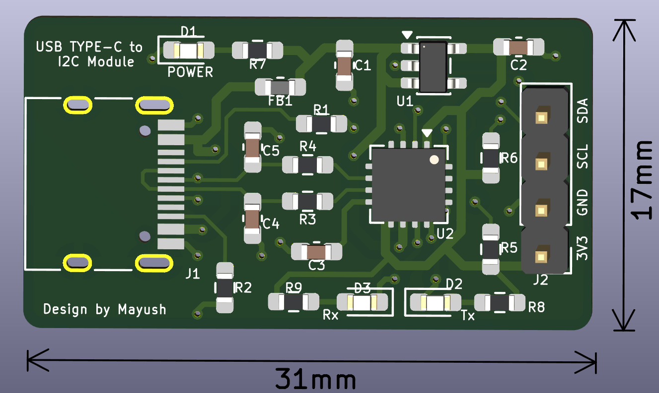 | 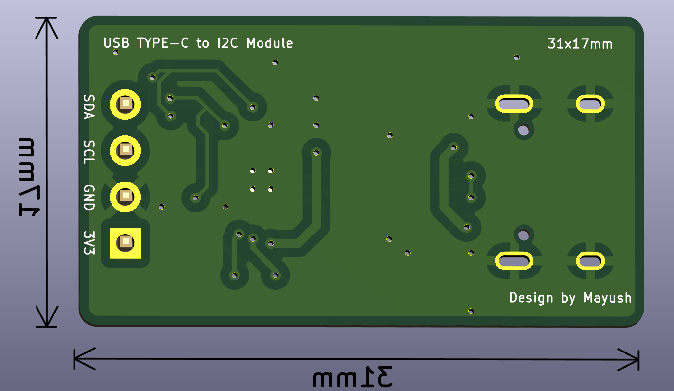 |
The module features a custom diagnostic LED array utilizing the configurable CBUS pins of the FT201X to provide immediate visual feedback of bus states:
| Feature | Specification |
|---|---|
| Dimensions | 31mm x 17mm |
| Layers | 2-Layer FR4 (Solid bottom ground plane) |
| Component Size | 0603 Imperial (Passives & LEDs) |
| Trace Width | 0.254mm (10 mil) standard |
| Input Interface | USB Type-C (Receptacle) |
| Output Interface | 4-Pin 2.54mm Header (3V3, GND, SCL, SDA) |
/Hardware - Source KiCad 7/8 project files (Schematic and PCB layout)./Fabrication - Manufacturing package (Gerbers, Excellon Drill files, and CSV BOM)./Docs - PDF schematics, 3D renders, and component datasheets.This board was intentionally designed to be hand-solderable despite its small size. All passive components use the _HandSoldering 0603 footprint variants to provide extended pad surface area for tweezer and iron assembly. Ensure the FT201X internal CBUS pins are configured via the FT_Prog utility to activate the TX and RX LED indicators after assembly.
Designed by MAYUSH RAHANGDALE
| Qty | Value | Footprint | References |
|---|---|---|---|
| 2 | 1u | Capacitor_SMD:C_0603_1608Metric_Pad1.08x0.95mm_HandSolder | C1, C2 |
| 2 | 2.2k | Resistor_SMD:R_0603_1608Metric_Pad0.98x0.95mm_HandSolder | R5, R6 |
| 2 | 27 | Resistor_SMD:R_0603_1608Metric_Pad0.98x0.95mm_HandSolder | R3, R4 |
| 2 | 330 | Resistor_SMD:R_0603_1608Metric_Pad0.98x0.95mm_HandSolder | R8, R9 |
| 2 | 47p | Capacitor_SMD:C_0603_1608Metric_Pad1.08x0.95mm_HandSolder | C4, C5 |
| 2 | 5.1k | Resistor_SMD:R_0603_1608Metric_Pad0.98x0.95mm_HandSolder | R1, R2 |
| 1 | 100n | Capacitor_SMD:C_0603_1608Metric_Pad1.08x0.95mm_HandSolder | C3 |
| 1 | 1k | Resistor_SMD:R_0603_1608Metric_Pad0.98x0.95mm_HandSolder | R7 |
| 1 | BLUE | LED_SMD:LED_0603_1608Metric_Pad1.05x0.95mm_HandSolder | D3 |
| 1 | Conn_01x04_Pin | Connector_PinHeader_2.54mm:PinHeader_1x04_P2.54mm_Vertical | J2 |
| 1 | FT201XQ | Package_DFN_QFN:QFN-16-1EP_4x4mm_P0.65mm_EP2.1x2.1mm | U2 |
| 1 | FerriteBead | Inductor_SMD:L_0603_1608Metric_Pad1.05x0.95mm_HandSolder | FB1 |
| 1 | GREEN | LED_SMD:LED_0603_1608Metric_Pad1.05x0.95mm_HandSolder | D2 |
| 1 | RED | LED_SMD:LED_0603_1608Metric_Pad1.05x0.95mm_HandSolder | D1 |
| 1 | TLV70233_SOT23-5 | Package_TO_SOT_SMD:SOT-23-5 | U1 |
| 1 | USB_C_Receptacle_USB2.0_16P | Connector_USB:USB_C_Receptacle_HRO_TYPE-C-31-M-12 | J1 |
tfindlay-au/GrovePower5
Further this project now includes a UART interface via an FTDI 201 chip which provides a serial interface to the grove device.

vitthal-rautwar/My_Kicad_projects
A collection of my KiCad-based electronics and PCB design projects, including circuit schematics, PCB layouts, component footprints, and design files.

VoronDesign/Voron-Hardware
Cool Hardware designed by the Voron Design group

hoglet67/RGBtoHDMI
Bare-metal Raspberry Pi project that provides pixel-perfect sampling of Retro Computer RGB/YUV video and conversion to HDMI

hackclub/OnBoard
💡 Join 1,000 teenagers and make your first PCB with a $100 grant!

abhishek-kakkar/BeagleLogic
A Software Suite that implements a logic analyzer with the PRU on the BeagleBone / BeagleBone Black.

Chrismettal/flipper-zero-backpacks
Backpack-style addon boards for the Flipper Zero!

It measures 31 × 17 mm and has 2 copper layers, 1.6 mm thick.
22 parts, built around the FT201XQ-R. The full list of its parts is on this page, with links to each part's symbol and footprint where PCBKit's library has them.
From the mayushhoon/usb-type-c-to-i2c-module repository on GitHub, at the commit this page was made from: the board is Hardware/USB_TO_I2C.kicad_pcb and its schematic Hardware/USB_TO_I2C.kicad_sch. PCBKit opens the board in the browser, with nothing to install.
Its repository states no licence, so its author keeps all rights: ask mayushhoon before reusing the design.