2 layers69.9 × 51.4 mm

 MayaPosch/DebounceHat24
Fully isolated, input debounce Hat for Raspberry Pi, for up to 6 switches, relays and powered devices
Debounce shield is an open-source printed circuit board by MayaPosch, from the MayaPosch/DebounceHat repository on GitHub, published under the BSD-3-Clause licence. It is a 2-layer board of 65 × 56 mm with 83 parts on 87 nets, routed with 552 tracks and 62 vias.
It is built around the RKZE-0505S/H, LTV-814 and 74LV14D, with the CAT24C32LI-, MAX16914AUB+ and RLS-126 among its other parts. Its parts include 20 resistors, 14 capacitors, 9 ICs, 7 diodes and 7 connectors. It belongs with the computers and single-board computers boards of this library.


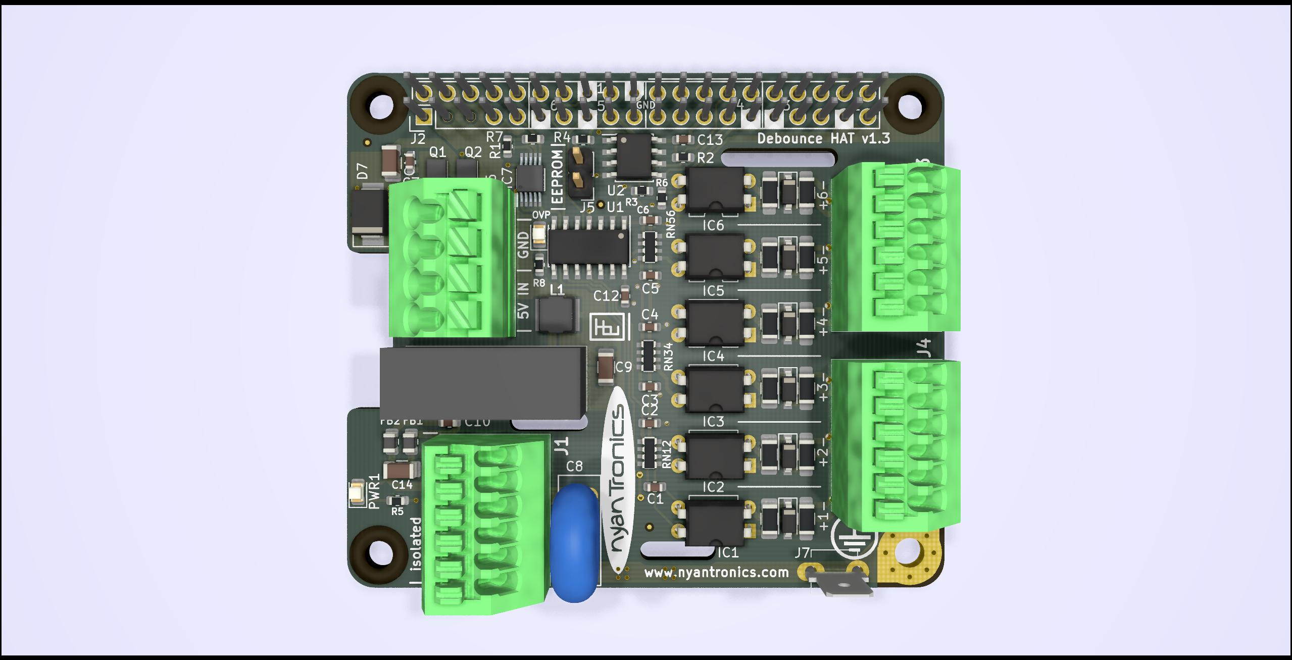
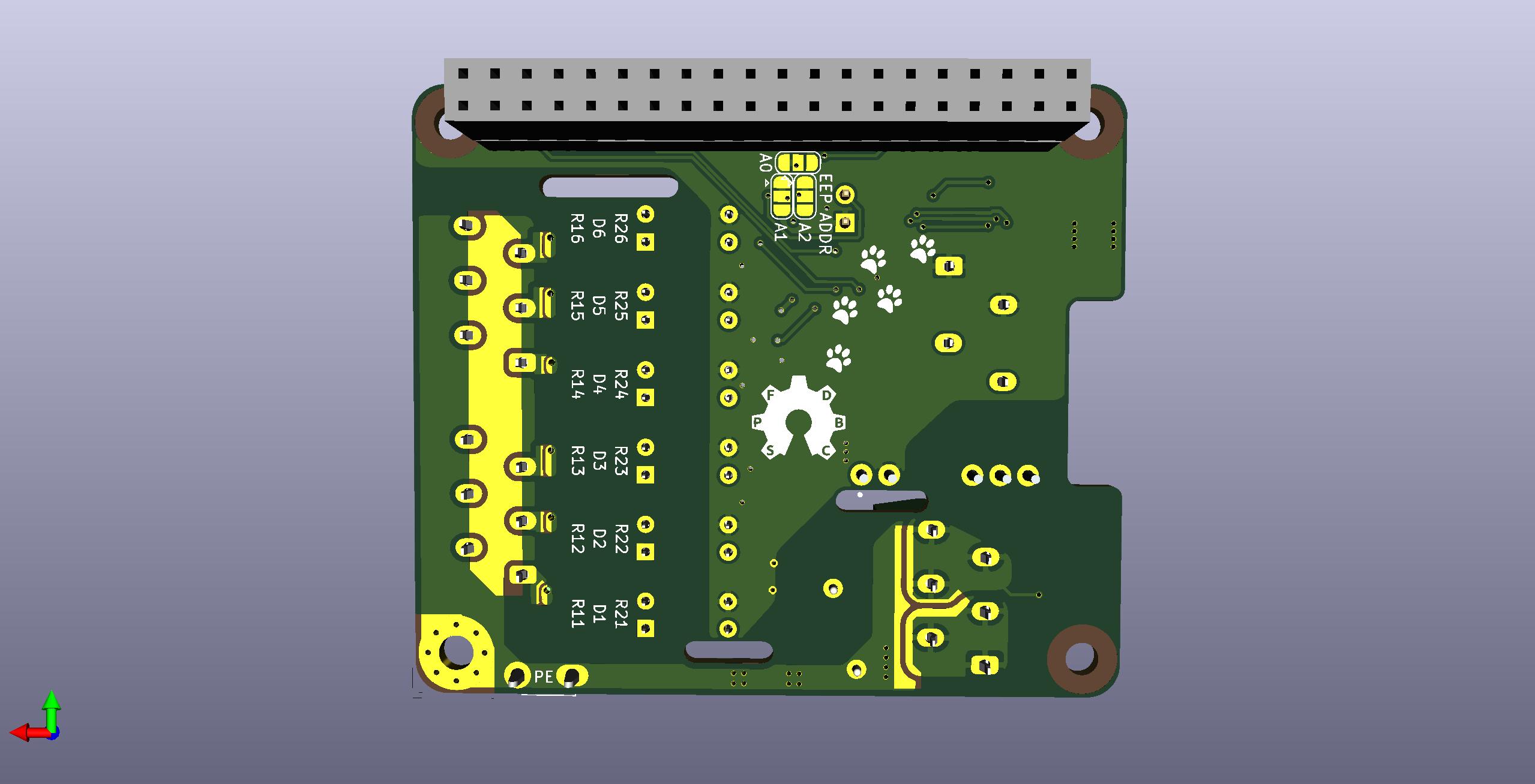
The Debounce HAT provides six opto-isolated digital input channels and is compatible with Raspberry Pi single board computers (SBC) with a 0.1" 2x20 pin header. The Debounce HAT is designed to protect the controller side from electrostatic discharge transients, returning currents through low voltage spark gaps and a dedicated chassis ground connection (PE).
All inputs can be driven with 3 to 24 V with arbitrary polarity. An on-board isolated 5 V DCDC converter provides an uncommitted supply of up to 400 mA for switches, active sensors or remote circuitry. The Debounce HAT implements filtering to suppress fast sequences of level changes typically encountered when using mechanical switches to provide plausible logic inputs to the target.
Further Information
A project page for this board along with ordering information can be found on the Nyantronics site.
Electrical Specifications:
Mechanical Specifications:
Typical Applications:
The six channels of the board are mapped to the following GPIO pins:
In the below graphic those pins are marked in yellow (DBH n):
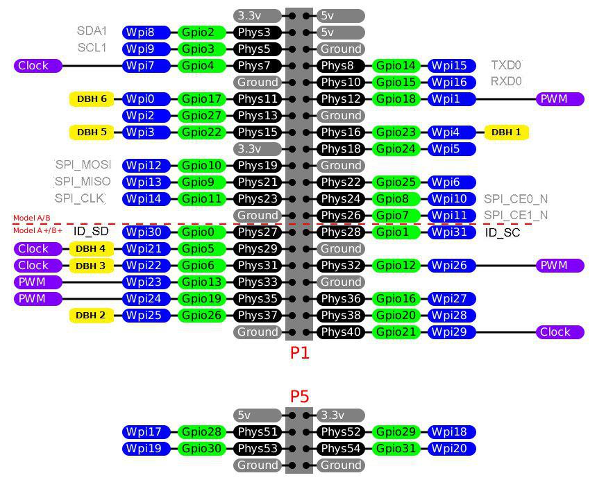
These pins are marked as probe points on the silkscreen of the 2x20 pin header.
The Debounce HAT can be powered from the SBC side. In this case the power terminals are disconnected to avoid back-driving.
When instead a 5V supply is connected to the Debounce HAT power input, the HAT provides advanced input protection, featuring load-disconnect overvoltage protection and low dropout ideal diode reverse polarity protection, making the 5V input and signal inputs +/- 24 V tolerant.
A target voltage of 2 to 5.5 V needs to be provided on pin 17 (typically 3.3 V supplied by the SBC).
With external 5V connected, additional hardware can be connected to the power terminal and draw up to 6 A.
The Debounce HAT provides an isolated source of 5 V for axuilliary circuitry (switches, sensors, other). The on-board DCDC converter is connected to the 5 V pins of the 2x20 pin header (pin 2, pin 4) and active in both above mentioned supply schemes.
The inputs are driven with an external voltage in the range of 3 to 24V. With mechanical switches, a circuit has to be formed with the on-board isolated 5 V output, or with an external power supply.
[Note] The Debounce HAT is not intended to be connected to mains-powered appliances. When a fault condition cannot be excluded in which any contact of the isolated side (signal inputs and isolated 5V) is live, a fuse must be placed between the HAT PE contact and the contact to ground.
The EEPROM configuration is provided in the eeprom_setting.txt file, which can be processed with the eepmake tool, and flashed to the EEPROM with eepflash. Both tools can be found at https://github.com/raspberrypi/hats/tree/master/eepromutils. The jumper (two pin header) allows for the EEPROM to be set to write-protected/write-enabled mode (WP, WE, respectively).
[Note] When not flashing the EEPROM, the EEPROM header should be set to Write-Protect (WP) mode by removing any electrical connection between the |EEPROM| pins on the two-pin header to prevent any accidental rewriting of the EEPROM's contents.
This board design has passed preliminary testing and is provided as-is. No responsibilities for damage or harm caused by its use will be accepted.
| Qty | Value | Footprint | References |
|---|---|---|---|
| 12 | 1k | Resistor_SMD:R_1206_3216Metric_Pad1.42x1.75mm_HandSolder | R11, R12, R13, R14, R15, R16, R21, R22, R23, R24, R25, R26 |
| 9 | 100nF | Capacitor_SMD:C_0603_1608Metric | C1, C2, C3, C4, C5, C6, C7, C12, C13 |
| 6 | D_TVS | Diode_SMD:D_SOD-123 | D1, D2, D3, D4, D5, D6 |
| 6 | LTV-814 | Package_DIP:DIP-4_W7.62mm | IC1, IC2, IC3, IC4, IC5, IC6 |
| 4 | 1k | Resistor_SMD:R_0603_1608Metric | R4, R5, R6, R7 |
| 4 | 3.9k | Resistor_SMD:R_0603_1608Metric | R1, R2, R3, R8 |
| 3 | RPi_Hat:RPi_Hat_Mounting_Hole | , , | |
| 3 | Conn_01x06 | Phoenix_Contact_1990041:1990041 | J1, J3, J4 |
| 3 | R_Pack04 | Resistor_SMD:R_Array_Convex_4x0603 | RN12, RN34, RN56 |
| 3 | SJ3_Bridged12 | Jumper:SolderJumper-3_P1.3mm_Bridged12_RoundedPad1.0x1.5mm | JP1, JP2, JP3 |
| 2 | 10uF/25V | Capacitor_SMD:C_1206_3216Metric | C9, C14 |
| 2 | DMP3028LFDE7 | DMP2066UFDE7:U-DFN2020-6 | Q1, Q2 |
| 2 | FB | Inductor_SMD:L_0805_2012Metric | FB1, FB2 |
| 2 | LED | LED_SMD:LED_0805_2012Metric | OVP1, PWR1 |
| 1 | 100nF/50V | Capacitor_SMD:C_0603_1608Metric | C10 |
| 1 | 10uF/35V | Capacitor_SMD:C_1206_3216Metric | C11 |
| 1 | 1285 | Keystone_1285:1285 | J7 |
| 1 | 1985218 | Phoenix_Contact_1985218:1985218 | J6 |
| 1 | 220pF/440VAC | Varistor:RV_Disc_D12mm_W4.6mm_P7.5mm | C8 |
| 1 | 74LV14D | Package_SO:SOIC-14_3.9x8.7mm_P1.27mm | U1 |
| 1 | CAT24C32 | Package_SO:SOIC-8_3.9x4.9mm_P1.27mm | U2 |
| 1 | Conn_01x02 | Connector_PinHeader_2.54mm:PinHeader_1x02_P2.54mm_Vertical | J5 |
| 1 | D_TVS | Diode_SMD:D_SMB | D7 |
| 1 | LOGO | libs:nyantronics_logo | G*** |
| 1 | LOGO | libs:earth_pe | G*** |
| 1 | LOGO | libs:kitten_paw_prints | G*** |
| 1 | LOGO | oshw:oshw | G*** |
| 1 | MAX16914AUB+ | MAX16914AUB+:SOP50P490X110-10N | IC7 |
| 1 | MountingHole_Pad | MountingHole:MountingHole_3.5mm_Pad_Via | H1 |
| 1 | RKZE-0505S/H | RKZE-0505S:RKZE0512SHP | PS1 |
| 1 | RLS-126 | RLS-126:RLS126 | L1 |
| 1 | RPi_GPIO | RPi_Hat:Pin_Header_Straight_2x20 | J2 |
The 79 most common of 83 parts.
It measures 65 × 56 mm and has 2 copper layers, 1.6 mm thick.
83 parts, built around the RKZE-0505S/H, LTV-814, 74LV14D and CAT24C32LI-. The full list of its parts is on this page, with links to each part's symbol and footprint where PCBKit's library has them.
From the MayaPosch/DebounceHat repository on GitHub, at the commit this page was made from: the board is debounce_shield.kicad_pcb. PCBKit opens the board in the browser, with nothing to install.
Its repository publishes it under the BSD-3-Clause licence: you may reuse it on that licence's terms (keep the author's notice, and for a copyleft licence share your changes alike).

rabid-inventor/mc68xx-boards
collection of PCB's based around the Motorola MC6800 series processor

MARS-UVA/Jetson_Extension_Board
KiCad design files for the Jetson Extension Board

Miceuz/triac-bloc
An universal power block based on triac. In essence this is a solid state relay with some bells and whistles

Domochip/WTeleInfo
Un D1 Mini et quelques composants pour envoyer votre Téléinfo (Compteur EDF) sur votre Domotique

tdouez/TeleinfoMySensors
Interface Téléinfo pour compteur Linky avec MySensors

synfinatic/GoProControl
GoPro WiFi controller board using an ESP8266 allowing easy integration with other circuits

markus-k/led-controller-hardware
KiCAD schematics and design files for my LED controller.