2 layers50.3 × 59.3 mm
WireTesterV1
maxconine/Cable-Tester
A device to quickly test cables on robots at the press of a button.
19 parts
 maxconine/Cable-Tester
A device to quickly test cables on robots at the press of a button.
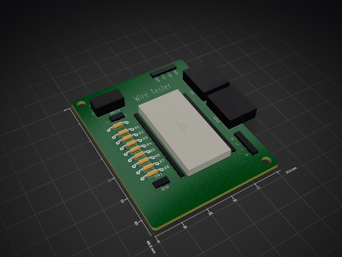
WireTester is an open-source printed circuit board by maxconine, from the maxconine/Cable-Tester repository on GitHub. It is a 2-layer board of 51.5 × 66.5 mm with 19 parts on 40 nets, routed with 195 tracks and 0 vias.
Its parts include 8 resistors, 4 ICs, 1 diode and 1 switch. It belongs with the NXP (LPC, Kinetis, i.MX RT) boards of this library.
Handheld continuity tester for 4-conductor power + CAN harnesses. A Teensy 4.0 on a custom PCB drives each conductor in turn, senses which lines light up at the far end, and reports opens, shorts, and miswires on an OLED with pass/fail tones. In Arm mode it also measures the resistance between the CAN conductors.
The four conductors are -, +, Low, and High (CAN Low / CAN High).
A Teensy 4.0 on a custom "Wire Tester" PCB, battery powered through a slide switch and a Schottky diode (so USB and battery can be connected at once), with a 128×64 I2C OLED, Test and Mode buttons, and a piezo buzzer. The whole thing lives in a 3D-printed enclosure with the buttons on a small perfboard behind the faceplate.
| Function | Pin(s) | Notes |
|---|---|---|
| Drive outputs | 0, 1, 2, 3 | Through series resistors R1–R4 (1.5 kΩ) |
| Sense inputs | 14, 15, 16, 17 | A0–A3, with pull-downs R5–R8 (10 kΩ to GND) |
| Test button | 21 | To GND, internal pull-up (pressed = LOW) |
| Mode button | 22 | To GND, internal pull-up (pressed = LOW) |
| Piezo buzzer | 13 | Passive, to GND |
| OLED SDA / SCL | 18 / 19 | SSD1306 at I2C address 0x3C |
Drive index n and sense index n are the two ends of the same conductor, in the order -, +, Low, High. A correctly wired harness therefore lights only the matching sense input.
The series resistors limit current into a shorted harness, and the pull-downs guarantee every sense line reads LOW unless it is actively driven through the cable. The sense pins double as analog inputs for the resistance measurement.
The harness under test plugs into In1 at one end and Out1 / Out2 at the other. Out1 and Out2 are wired in parallel so either a connector or bare probe leads can be used. All three carry the same -, +, Low, High ordering.
KiCad sources, gerbers, drill files, and a STEP export live under WireTester/, with the probe board under WireTester/ProbeBoard/.
Adafruit SSD1306Adafruit GFX LibraryCableTester.ino and upload.Wire, analogReadResolution(), and analogWriteFrequency() come from the Teensy core, so no other dependencies are needed.
Every test is built from the same primitive: drive one conductor, read all four.
INPUT STUCK HIGH.-, bit 1 = +, bit 2 = Low, bit 3 = High). Voting rejects noise on a marginal connection.Settle timing depends on the mode: 100 ms settle with a 50 ms release for the static tests, and 8 ms / 2 ms for the flex test so scans repeat quickly.
The mask for each driven conductor is compared against the single bit that should be set:
| Mask | Meaning | Shown as |
|---|---|---|
| Exactly the expected bit | Correct | Counts toward a pass |
0 — nothing sensed | Broken conductor or bad crimp | <wire> OPEN |
| More than one bit | Conductor touching others | <wire> SHORT: <names> |
| One wrong bit | Landed on the wrong pin | <wire> -> <other> |
In Cable mode, when two conductors each reach only the other, the pair is collapsed into a single swap line such as + <-> Low instead of two separate miswire lines.
The Mode button cycles Cable → Arm → 10 Sec, and each mode has its own confirmation chime. The selected mode is shown on the ready screen.
Strict one-to-one check for a bare harness. Every conductor must reach itself and nothing else; any extra or missing connection fails.
Intended for a harness that is still attached to live arm electronics, where the CAN conductors are legitimately coupled through termination resistors. The continuity rules are the same as Cable mode with one exception: High reaching Low (or the reverse) is allowed instead of being flagged as a short. Every conductor must still reach itself.
After the continuity sweep the tester measures the resistance between the CAN conductors.
Beyond pass/fail continuity, the tester measures the resistance between the High and Low conductors — enough to tell a properly terminated CAN bus (~60 Ω, or ~120 Ω single-terminated) from a dead short or a missing terminator.
It works as a voltage divider using the existing drive hardware:
High is driven to 3.3 V and Low to GND, each through its 1.5 kΩ series resistor.R = 2 × R_series × |dV| / (V_drive − |dV|)
where R_series = 1500 Ω, V_drive = 3.3 V, dV = V_high − V_lowThe result is classified before it is reported:
| Condition | Reported as |
|---|---|
| Both sense lines below 0.2 V | OPEN — nothing connected |
| dV magnitude under 20 mV | SHORT — ~0 Ω, wires touching |
| dV magnitude within 50 mV of full scale | OPEN — no path between the conductors |
| Otherwise | Measured value in ohms |
A passing Arm test shows the value on the OLED in large text with an Ω symbol, labelled CAN High-Low (or OPEN if no path was found). The reading is informational and does not by itself fail the test — the one exception is a hard short, which is treated as the two conductors touching and reported as High-Low SHORT. On a failing Arm test the measured resistance is appended below the fault lines when there is room.
Catches intermittent faults that a static test walks straight past. The tester runs fast continuity scans in a loop for ten seconds while you flex, wiggle, and tug the harness — especially at the strain reliefs and connector backshells.
While it runs, the screen counts down and shows whether continuity is still clean. Per conductor the tester tallies open, short, and miswire events separately, remembers the first fault mask it saw, and stops early on the first bad scan. A pass reports how many scans completed clean, which is a rough measure of how much of the harness got exercised.
The fault screen reports the dominant fault type per conductor, so a wire that mostly drops out reads OPEN even if it also glitched into a neighbour once.
| Screen | When | Contents |
|---|---|---|
| Ready | Idle | Mode name, TESTER, and press test to begin |
| Testing | During a static test | Testing |
| Bend Wire | During the flex test | Countdown in seconds, plus Continuity OK or GLITCH DETECTED |
| Good | Pass | Large GOOD, plus mode detail: all wires correct, measured ohms, or scans completed |
| Bad | Fail | Large BAD, plus up to four fault lines |
The fault screen holds a maximum of four lines. INPUT STUCK HIGH and, in Arm mode, High-Low SHORT take priority over per-conductor faults. If a test fails but nothing could be attributed to a specific conductor, the screen reads UNKNOWN ERROR.
Results stay on screen until the next button press, and both buttons are ignored while a test is running.
| Event | Sound |
|---|---|
| Power on | Three-note rising chime |
| Mode change | Short two- or three-note motif, different per mode |
| Pass | Four-note rising arpeggio, played at low duty cycle so it stays quiet |
| Fail | Three harsh alternating low/high buzzes |
Connect at 115200 baud for detail the small display cannot fit. Every test prints a per-conductor verdict — GOOD, OPEN / NO CONTINUITY, SHORTED - reaches ..., or MISWIRED - reaches ... — along with any unexpected HIGH inputs seen before the test.
Arm mode adds the raw ADC counts, both sense voltages, the computed dV, and the final resistance, which is useful for sanity-checking a marginal harness. The flex test adds per-conductor event counts (OPEN x3, SHORT x1 -> High), the first fault seen on each conductor, the number of clean scans, and the total fault count.
The constants at the top of CableTester.ino cover most of what you would want to change:
| Constant | Default | Purpose |
|---|---|---|
NUM_WIRES | 4 | Conductor count; drivePins, sensePins, and wireNames must match |
wireNames | -, +, Low, High | Labels used on screen and over serial |
DRIVE_SERIES_OHMS | 1500.0 | Must match the fitted series resistors, or the resistance reading will be off |
OLED_ADDRESS | 0x3C | Some SSD1306 modules use 0x3D |
BUTTON_PIN / MODE_BUTTON_PIN | 21 / 22 | Test and Mode buttons |
Test durations and settle times are local constants: TEST_MS in runFlex10Test() sets the ten-second window, and testOneWire() / testOneWireFast() set the settle and release delays.
| Symptom | Likely cause |
|---|---|
Blank screen, OLED initialization failed. on serial | Wrong I2C address or SDA/SCL not on 18/19; firmware halts here by design |
INPUT STUCK HIGH before any test | External voltage on the harness, a missing pull-down, or a sense line shorted to power |
Everything reads OPEN | Harness not seated, or In1 and Out1/Out2 swapped end for end |
Resistance reads OPEN on a known-good CAN bus | Termination resistor missing or too large for the 1.5 kΩ divider to resolve |
| Resistance reads far from expected | DRIVE_SERIES_OHMS does not match the resistors actually fitted |
| Flex test passes on an intermittent harness | Not enough movement; flex at the connector backshells and strain reliefs |
High and Low. The + and - conductors are checked for continuity only.| Qty | Value | Footprint | References |
|---|---|---|---|
| 4 | 10kR | Resistor_THT:R_Axial_DIN0204_L3.6mm_D1.6mm_P7.62mm_Horizontal | R5, R6, R7, R8 |
| 4 | 1kR | Resistor_THT:R_Axial_DIN0204_L3.6mm_D1.6mm_P7.62mm_Horizontal | R1, R2, R3, R4 |
| 2 | ~ | 1_My_custom_library:Female_Header_pin_XT30 F | In1, Out1 |
| 2 | ~ | 1_My_custom_library:4holes | Out2, U4 |
| 1 | D_Schottky | Resistor_THT:R_Axial_DIN0204_L3.6mm_D1.6mm_P7.62mm_Horizontal | D1 |
| 1 | SW_Push_Open | 1_My_custom_library:2holes | SW1 |
| 1 | Teensy4.0 | DEV-15583:MODULE_DEV-15583 | U1 |
| 1 | ~ | 1_My_custom_library:RightSideArduino | U5 |
| 1 | ~ | 1_My_custom_library:slideSW | U3 |
| 1 | ~ | 1_My_custom_library:2holes | BATT1 |
| 1 | ~ | 1_My_custom_library:LeftSideArduino | U2 |
maxconine/Cable-Tester
A device to quickly test cables on robots at the press of a button.

maxconine/Cable-Tester
A device to quickly test cables on robots at the press of a button.


hackclub/OnBoard
💡 Join 1,000 teenagers and make your first PCB with a $100 grant!

polpo/picogus
Emulation of ISA sound cards and CD-ROM on Raspberry Pi Pico (GUS, SB/Adlib, MPU-401, Tandy, CMS, Panasonic CD-ROM) with USB mouse/joystick support


nkitanov/iaq_board
IAQ Board is a DIY (Do-It-Yourself) device for measuring internal air quality


Ardumower/ardumower
Develop an open source robotic lawn mower (HW+SW reference platform)

zmaker/arduino_cookbook
gli sketch del nuovo progetto Arduino Cookbook e dei video di YouTube
It measures 51.5 × 66.5 mm and has 2 copper layers, 1.6 mm thick.
19 parts. The full list of its parts is on this page, with links to each part's symbol and footprint where PCBKit's library has them.
From the maxconine/Cable-Tester repository on GitHub, at the commit this page was made from: the board is WireTester/WireTester.kicad_pcb and its schematic WireTester/ProbeBoard/ProbeBoard.kicad_sch. PCBKit opens the board in the browser, with nothing to install.
Its repository states no licence, so its author keeps all rights: ask maxconine before reusing the design.