2 layers
IEC-62056-21-Optical Probe
twam/IEC-62056-21-Optical-Probe
Optical-Probe for reading out power meters supporting IEC 62056-21 via USB
38 parts33

 maunope/metroBlindDriver
A simple Arduino based driver board for Rome Metropolitana A trains stops blinds
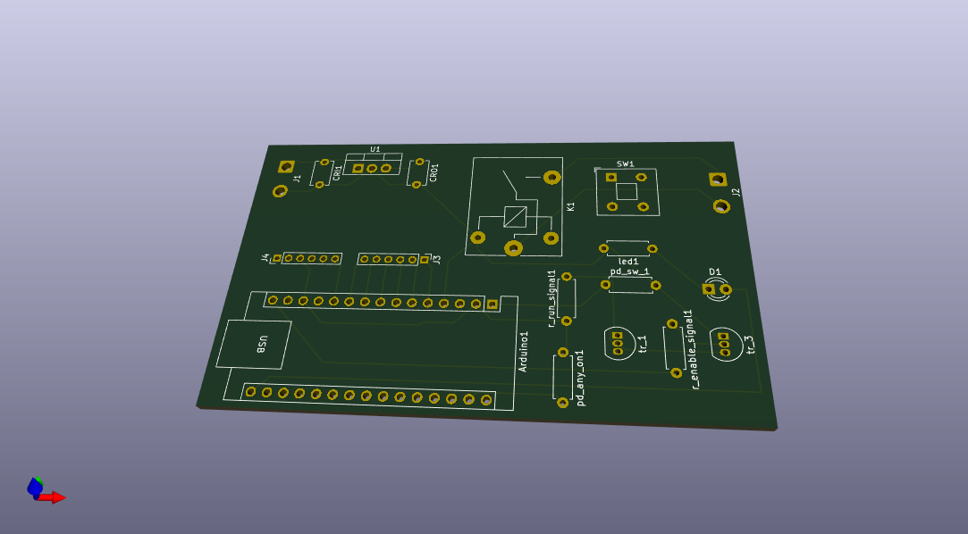
MetroBlindDriver is an open-source printed circuit board by maunope, from the maunope/metroBlindDriver repository on GitHub. It is a 2-layer board of 83.5 × 49.5 mm with 18 parts on 41 nets, routed with 108 tracks and 0 vias.
It is built around the LM7805, S8050 and S8550. Its parts include 4 diodes, 4 connectors, 2 switches and 1 IC. It belongs with the AVR (ATmega, ATtiny) boards of this library.


This is still a prototype; the circuit design was built and tested on a perfboard, the KiCad board design was never tested. Use at your own risk and plz don't come whining if you damage stuff or set your house on fire.
This project entails working with a 220V powered device with a metal chassis and no grounding. These devices are 40+ years old and saw lots of abuse; wire insulation may fail, and motor windings may short circuit. Before wiring anything up, check impedance between the chassis, the engine hull, and all contacts carrying 220V power; anything below 2 megaohms means insulation needs to be re-checked. Consider wiring the blind chassis to the ground line for additional safety.
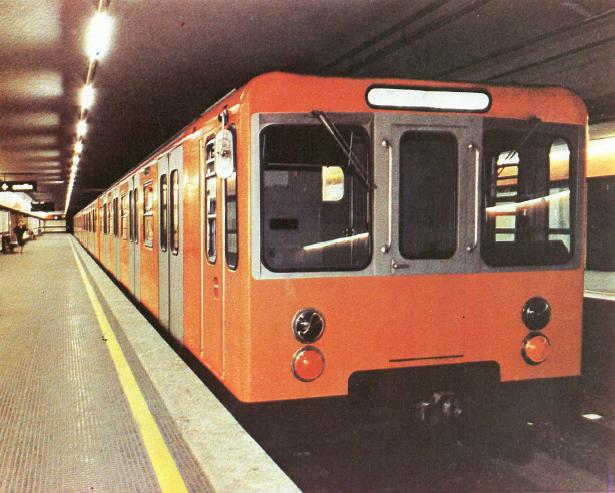
Arduino-based driver board to control Acotral MA100 electric locomotives' front and side stops blinds.
Acotral MA100s were first issued to Rome's "A" metro line where they were in service between 1980 and 2005, before being overhauled/modified and reassigned to the Roma Lido line until their decommissioning in 2018.
Stops signaling blinds coming from wagon dismantling started circulating among flip clock collectors and have become a somewhat common find on online marketplaces.
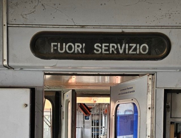
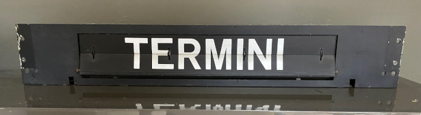
Blinds are controlled through a 7-bit string identifying stops and are powered at 110V AC (motor) / 48V DC (control). This project emulates original locomotive control signals to drive them and display stops.
The board design in this project runs 5V DC control signals and 220V power; it requires minimal modifications to the original blinds' wiring. It is fairly easy, however, to adapt it to run 48V/110V to 100% preserve the integrity of the original wiring.
The LATERAL_BLIND compile flag enables a command table built for smaller punched rollers found on side-mounted train blinds. This mode is intended to address blinds with smaller punched rollers, those mounted on the side of trains rather than the larger frontal rollers.
On the specimen I tested, the pinout was different compared to the larger frontal roller, but this may not always be true. If your roller is different, you may need to recreate the command array for your exact roller.
In manual mode (default), stops are selected through serial port commands or single button presses. The board LED is lit during Manual mode.
Program mode automatically loops a sequence of stops, one step every hour by default. The program will be resumed from the last reached stop in case of power OFF/ON; the hourly step timer will be reset. The board LED is off during Program mode.
To switch between modes, either use serial commands or press the board button for 3 seconds.
Check the schematic in this repo; I've built and tested it on perfboard. The board design might not be 100% correct, and the layout could definitely use some improvement.
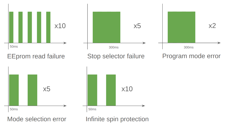
How to read LED signals
Either for good or bad news, the Arduino board LED will flash.
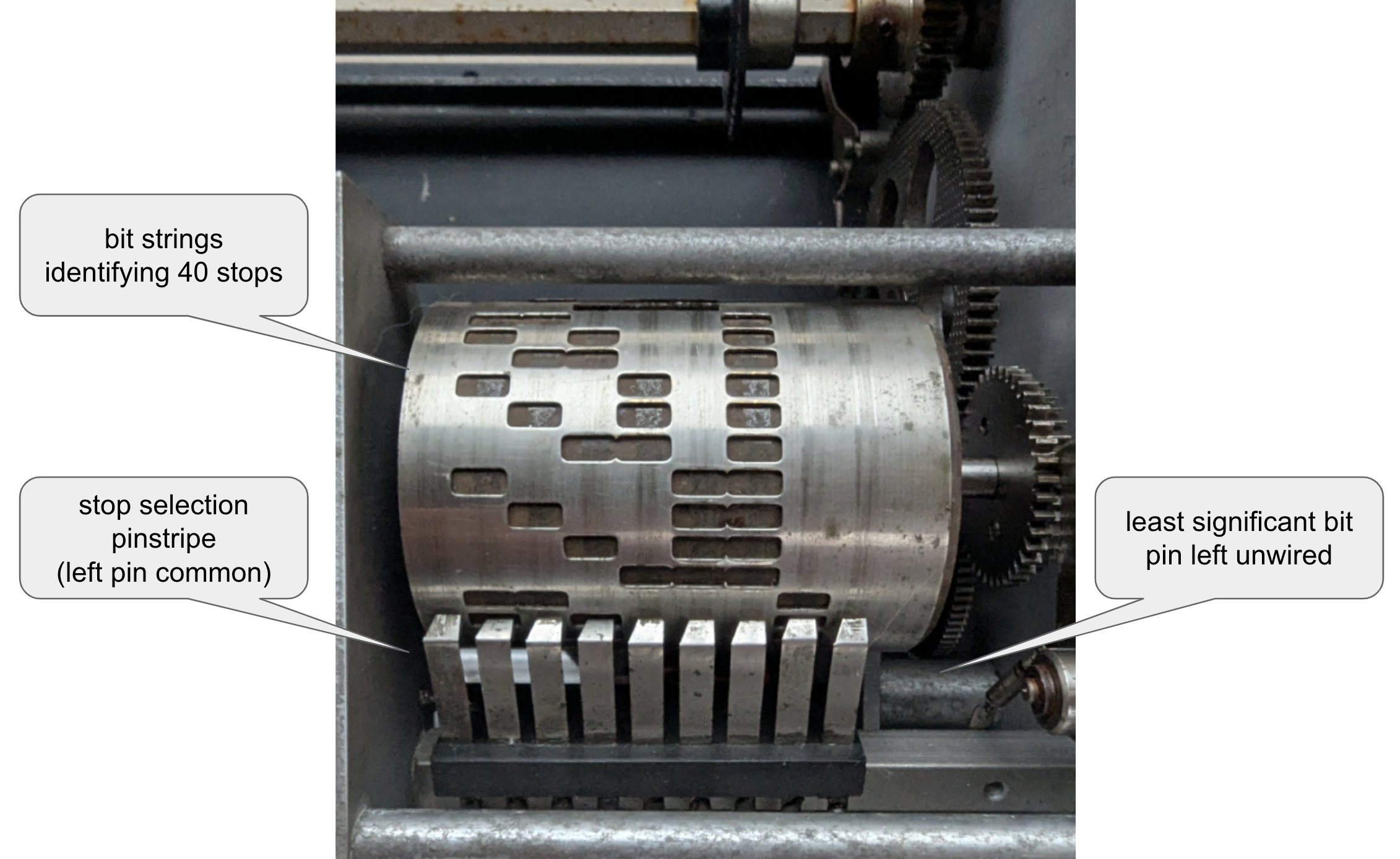
A punched roller is used to encode 40 unique blind positions. When a string of bits is applied to the pinstripe, the motor spins until the holes combination under the pinstripe matches powered pins, i.e.:
The original control board has 7 control pins, 2 relay coil pins, and 2 motor power pins, exposed through a DIN 41622 male connector on the side or back panel.
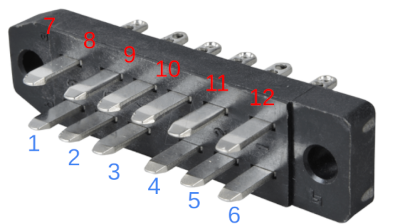
The original wiring:
The blind board schematic is available in "metroBlindDriver blind board" KiCad design:
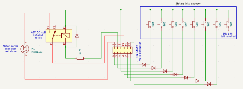
In the original blind design, 48V DC bits would be fed into pins 1-6 and 12; they would reach the control roller through diodes and would power the 48V relay coil through the roller common pin until the desired stop was reached.
The original blind wiring can be easily modified to accept standard household 220V AC power and 5V DC signals.
IMPORTANT: Don't use this board design with 48V signals to avoid damage and fire hazard!
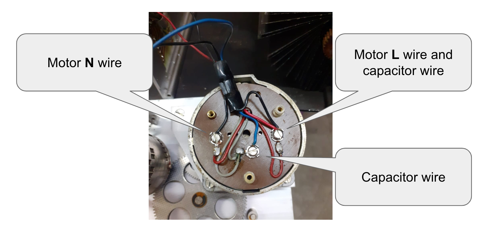
IMPORTANT: Don't run 220V AC through the motor before its coils are wired in series to avoid damage and fire hazard!
220V AC motor wiring Wire the motor as shown in the picture below to drive it with 220V AC power. Plastic motor caps on most (all?) blinds have diagrams explaining how to wire coils in series/parallel.
5V DC external relay wiring
To bypass the 48V coil and use an external relay, clip the motor N wire from the connector board trace (board end, not motor end!) and solder it to the top left pin on the DIN connector. If in doubt, use the only pin trace with no wires attached.
Replacing the original 48V relay with a 5V or 12V one isn't sufficient, as the coil has a 4kohm resistor wired in series; plus, compatible relays are out of production, hard to source, and quite expensive.
I wanted to preserve the original circuitry as much as possible, but definitely didn't want to faff with 48V signals. I figured since I had already wired the motor for 220V AC, another small modification wouldn't matter much, and moving a wire to a different pin seemed way less invasive than replacing a relay and a big *ss resistor. You might want to do things differently here; the circuit is easy enough to work with, these are just my 2c :-)
Rewired schematic below:
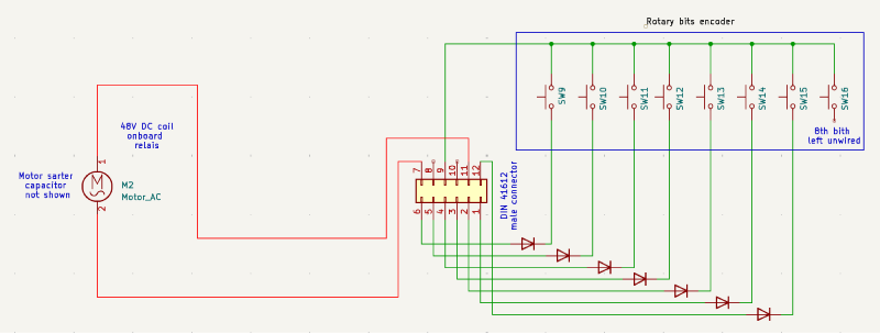
The new wiring:
First things first, let's not fry stuff
By default, the controller will wait for commands in manual mode with the board LED ON.
Commands format: (<<|>>)[A-Z,0-9]+
One command per line; the parser is pretty crude, please stick to tested commands ;-)
Available commands:
-DEBUG_MODE enable serial port debug messages, disable sleep mode
The control roller pinstripe 8 signals encode 40 unique bit strings, each with three raised bits (i.e., 0b11001000, 0b00110010). This allows moving from any stop to any other by applying the destination code bit string to stop selection pins.
At least, this is how the control roller would work hadn't its original designers decided to leave the rightmost pin unwired.
As a result, 5 out of 40 stops are encoded by only 2 wired pins and only work when selected starting from the 13 stops right behind them. The matrix below highlights misencoded stops and the stops that would be wrongly displayed when their code is used, i.e.:
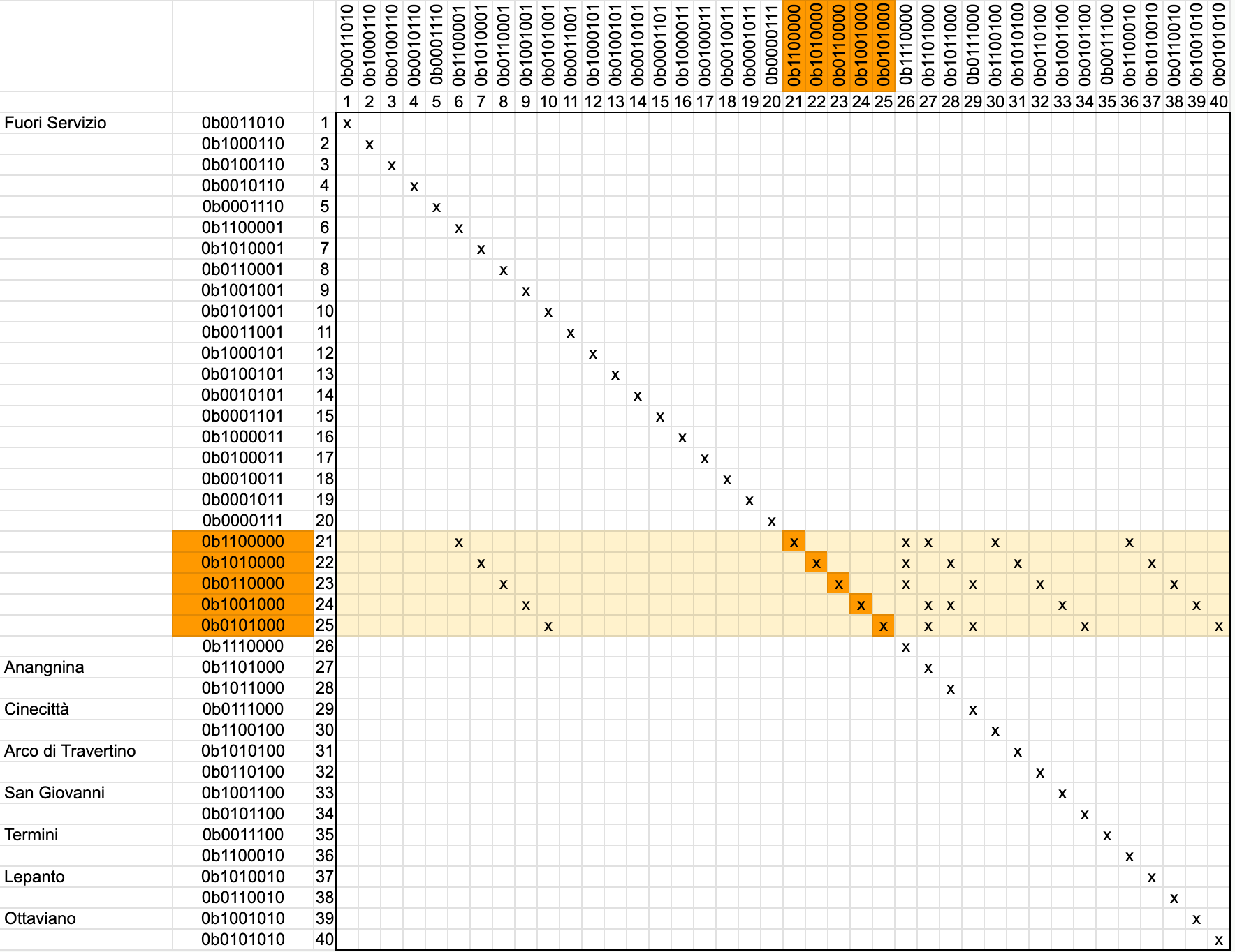
This behavior did not affect actual service on Roma Metro A as the 5 impacted stops were blank. I decided to leave it unchanged as an interesting quirk of the original design; you might want to fix it if you plan to display anything on stops 21-25 :-D
Q: I can't tell what's going on with EEPROM data.
A: The <<EEPROMDATA command can extract all the info saved on the EEPROM.
Q: I keep getting "nonexistent stop" error.
A: Check wiring; any short circuit? Any missing wire?
Q: Motor buzzes and doesn't spin! What's wrong?
A: Have you rewired the motor correctly?
Q: I rebooted the board, and all my configurations are lost.
A: Run >>EEPROMDATA to persist configuration on EEPROM.
Q: I have disassembled the punched roller and now it doesn't stop on the right positions.
A: If the roller is misaligned, it will not work correctly. The solution is to disassemble it again, align it to the right stop, and reassemble it. It is possible to fine tune it by undoing the screw on the roller side and moving the outer plate slightly.
Q: That PCB design is lame!
A: It is. Any help much appreciated! ;-)
| Qty | Value | Footprint | References |
|---|---|---|---|
| 3 | 1k | Resistor_THT:R_Axial_DIN0207_L6.3mm_D2.5mm_P7.62mm_Horizontal | led1, pd_sw_1, r_run_signal1 |
| 1 | 0.1uf | Capacitor_THT:C_Disc_D5.1mm_W3.2mm_P5.00mm | CRI1 |
| 1 | 100k | Resistor_THT:R_Axial_DIN0207_L6.3mm_D2.5mm_P7.62mm_Horizontal | pd_any_on1 |
| 1 | 10uF | Capacitor_THT:C_Disc_D5.1mm_W3.2mm_P5.00mm | CRO1 |
| 1 | 12V_in | Connector_Wire:SolderWire-1sqmm_1x02_P5.4mm_D1.4mm_OD2.7mm | J1 |
| 1 | 220V | Connector_Wire:SolderWire-1sqmm_1x02_P5.4mm_D1.4mm_OD2.7mm | J2 |
| 1 | 47 | Resistor_THT:R_Axial_DIN0207_L6.3mm_D2.5mm_P7.62mm_Horizontal | r_enable_signal1 |
| 1 | Arduino_Nano_v3.x | Module:Arduino_Nano | Arduino1 |
| 1 | LED | LED_THT:LED_D3.0mm | D1 |
| 1 | LM7805 | Package_TO_SOT_THT:TO-220-3_Vertical | U1 |
| 1 | S8050 | Package_TO_SOT_THT:TO-92_Inline | tr_1 |
| 1 | S8550 | Package_TO_SOT_THT:TO-92_Inline | tr_3 |
| 1 | SW_MEC_5E | Button_Switch_THT:SW_Push_2P1T_Toggle_CK_PVA1xxH1xxxxxxV2 | SW1 |
| 1 | blind_pins_bottom_row | Connector_PinHeader_2.00mm:PinHeader_1x06_P2.00mm_Vertical | J3 |
| 1 | blind_pins_top_row | Connector_PinHeader_2.00mm:PinHeader_1x06_P2.00mm_Vertical | J4 |
| 1 | out relais | Relay_THT:Relay_SPST_SANYOU_SRD_Series_Form_A | K1 |
It measures 83.5 × 49.5 mm and has 2 copper layers, 1.6 mm thick.
18 parts, built around the LM7805, S8050 and S8550. The full list of its parts is on this page, with links to each part's symbol and footprint where PCBKit's library has them.
From the maunope/metroBlindDriver repository on GitHub, at the commit this page was made from: the board is metroBlindDriver kicad/metroBlindDriver.kicad_pcb and its schematic metroBlinDriver blind board/metroBlinDriver blind board.kicad_sch. PCBKit opens the board in the browser, with nothing to install.
Its repository states no licence, so its author keeps all rights: ask maunope before reusing the design.
twam/IEC-62056-21-Optical-Probe
Optical-Probe for reading out power meters supporting IEC 62056-21 via USB

ambadran/spot-welder
Battery Spot Welder Circuit Using Capactive Discharge (CD) Circuit


xDuinoRails/xDuinoRails_Hermes-M
Your DCC/Railcom signals and a +5V power source for your microcontroller on a breadboard

xDuinoRails/xDuinoRails_Thor
Make a Seeed XIAO board a mtc21 decoder, all the electronics needed is on this little board: - mtc21/plux16 compatible connector - DC Motor - 2x Functions - DCC / DCC-ACK / RailCom

ambadran/Revolute_Joint
Optimal Cheap Robotic Actuator allowing high Torque and moderate Speed. Allow PRECISE Absolute, Speed and Torque Control. Using 3D-printed Cycloidal Drive, Custom PCB and LQR Control Algorithm.

chatelao/xDuinoRail-Decoder
The friendly decoder development plattform for model railroad tinkers.
