
2 layers113 × 62.2 mm
FullScope
tvlad1234/pillScopePlus
Oscilloscope based around the STM32F401 Black Pill and a color LCD screen
15 parts165Apache-2.0

 mattwach/motorized_macro_rail7
Contains a hardware design and firmware for a stepper-motor-powered macro rail module. The module is designed to be attachable to a manual rail. Another goal is to make the module easily removed in for cases where manual mode is preferred (such as field work).
Macro rail kicad is an open-source printed circuit board by mattwach, from the mattwach/motorized_macro_rail repository on GitHub. It is a 2-layer board of 119.4 × 57.2 mm with 20 parts on 59 nets, routed with 160 tracks and 11 vias.
It is built around the LM7805. Its parts include 5 connectors, 4 switches, 3 capacitors, 3 ICs and 1 resistor. It belongs with the robots and motor control boards and the RP2040 boards of this library.
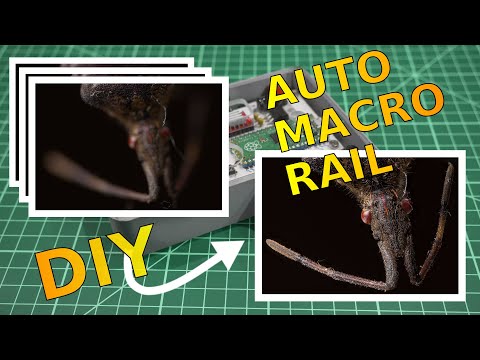
Instructables Link is here
This is a project for a motorized macro focusing rail. It is used with special "stacking" software to increase the depth of field of macro images. This project is presented as a modification to an existing commercial rail, but could be extended to use a custom built rail (using steel rods and linear bearings commonly used in at-home 3D printers and CNC mahines).
Taking images of very small objects is known as macro photography. Using a specialized lens, or an attachable modifier makes this type of photography possible.
Due to the physics of photographic lenses, taking photos of very small objects typically has a very low depth of field, where only a thin plane of the object appears in focus, often much less than 1mm.
In general photography, it is possible to "stop down" the aperture to increase the depth of field. That is true in macro photography as well, but even stopping down often does not sufficiently address the depth of field problem.
A modern solution is to take many photos where the focus point is slightly shifted, then combine these using software. For example, we would take these photos:
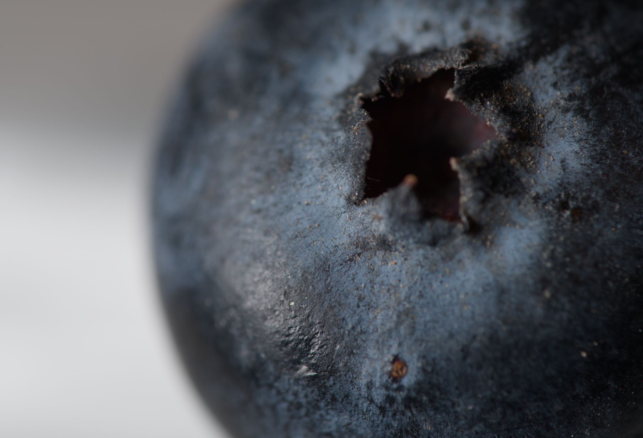
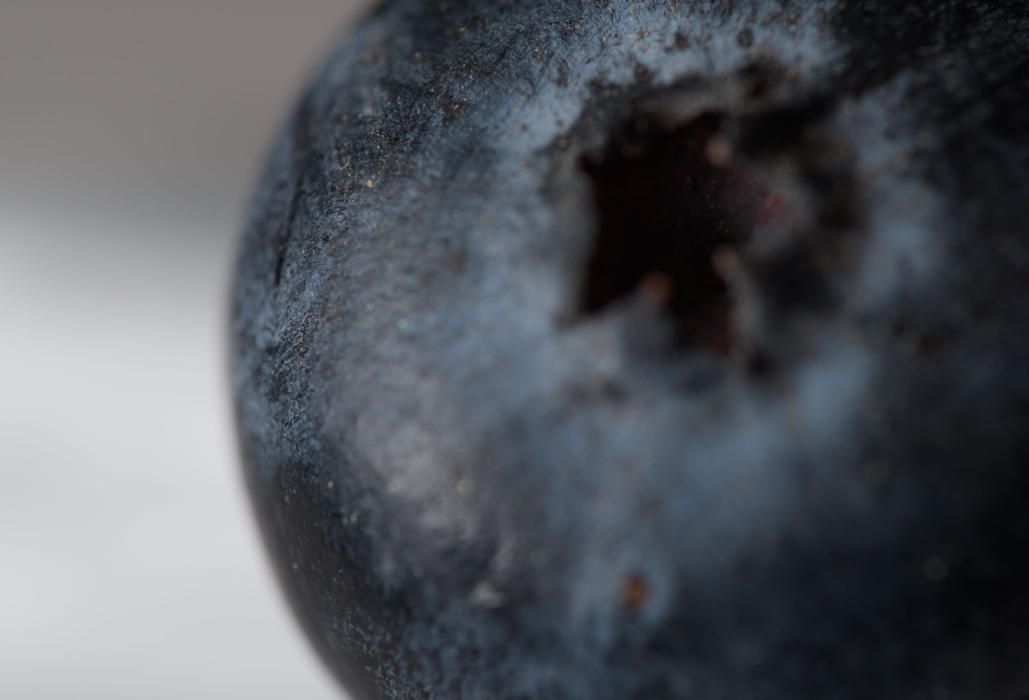
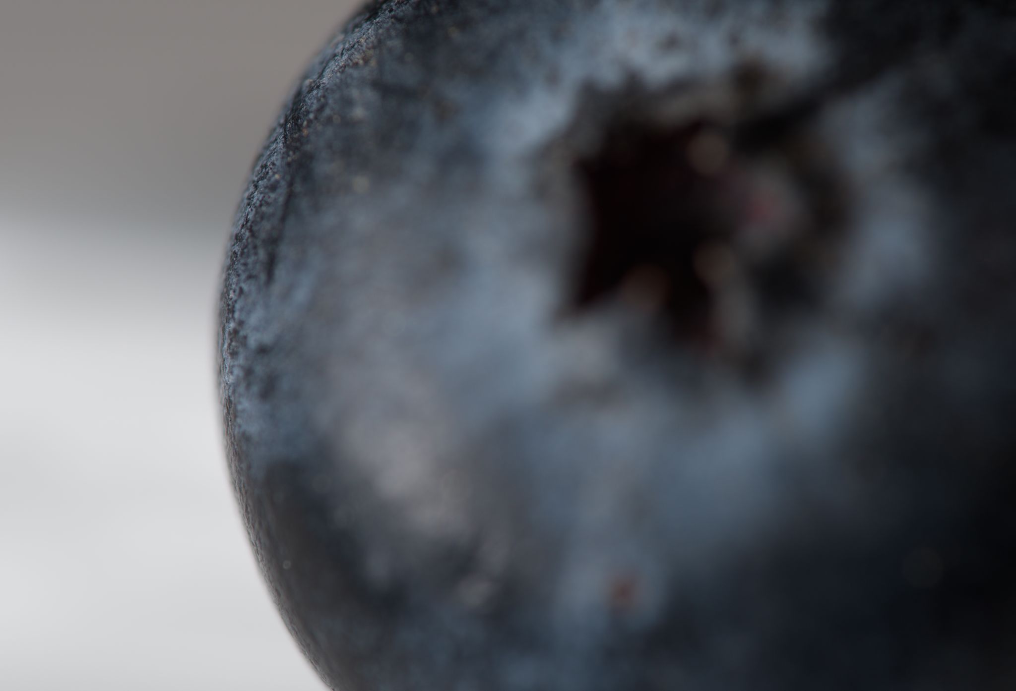 (and 29 more)
and combine them into this "stacked" image:
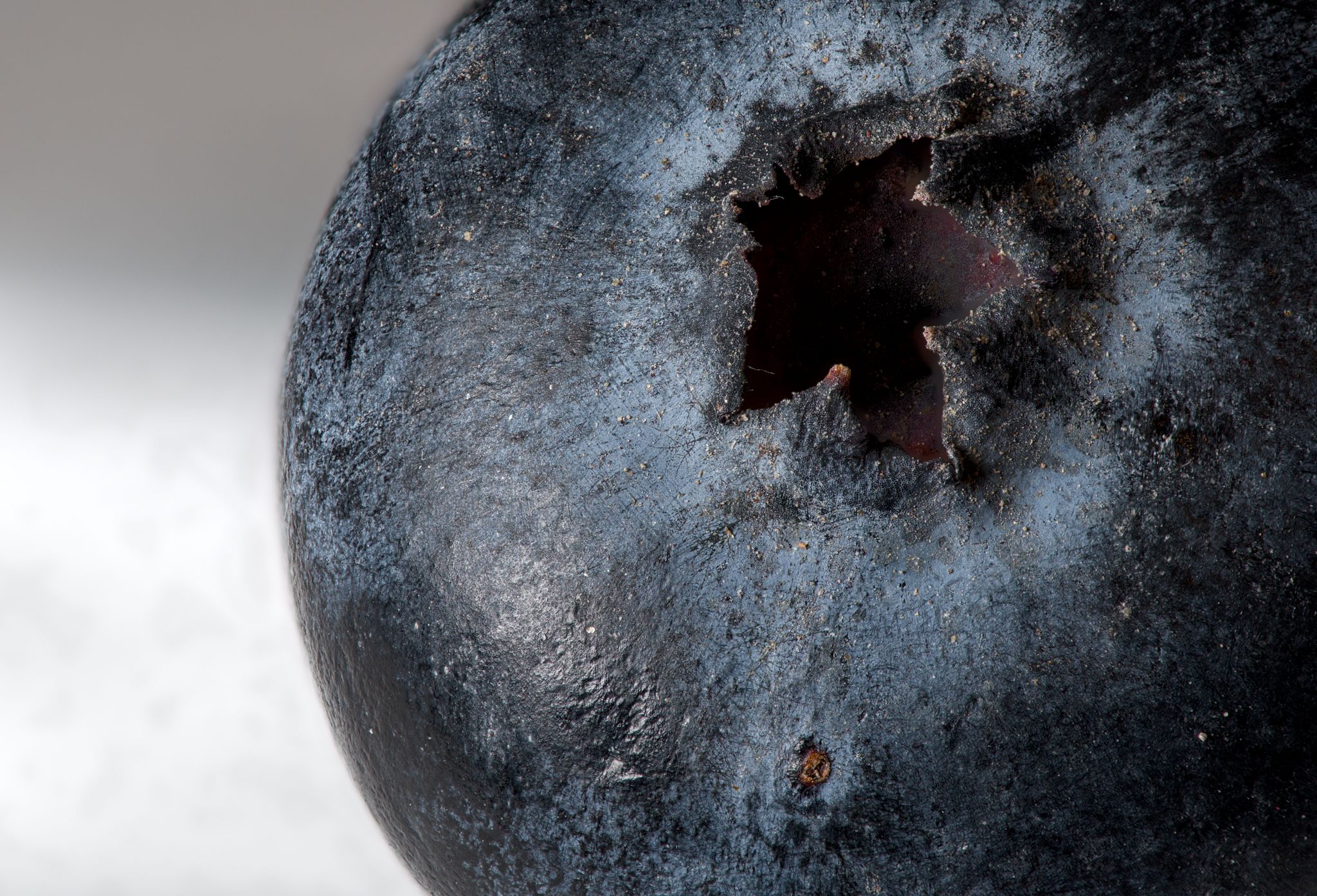
The project here helps to take the captured photos in an automated and consistent way.
Note that taking these photos requires either a specialized lens, an attachable lens filter or an extension tube. There are endless resources on the web on gettings started. Here is one for the basics. Here is one for extreme macro, which is where a rail comes into play. The amount of detail in this article is impressive and seems beyond what you'll need to know to start experimenting, but a useful reference as you progress.
These are the parts and equipment I used. Of course, any of them could be swapped with alternatives with varying degrees of challenge depending on the part:
Prices are what I found in late 2024. I am mostly suggesting Digikey here because they let you purchase low part counts.
You will also need a rail. I went with the NM-200s
which I acquired on sale for $150. I'd say the NM-180s
is likely as good for $130 retail. There are also a number of cheaper options that I have no
direct experience with, such as this one for $89. If you go with a NM-XX0s rail as I used, you can use the provided .STL files directly. For other rails
you will need to resize the adapter using the free OpenSCAD and instructions provided later
in this document.
Here is the schematic.
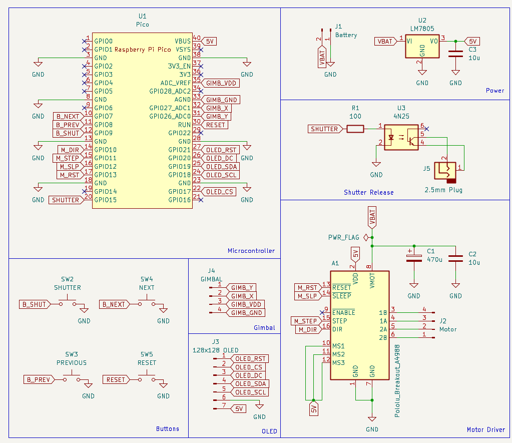
There are around 2 dozen connections to be made here which makes most assembly methods possible. Here is the whole thing implemented on a breadboard:
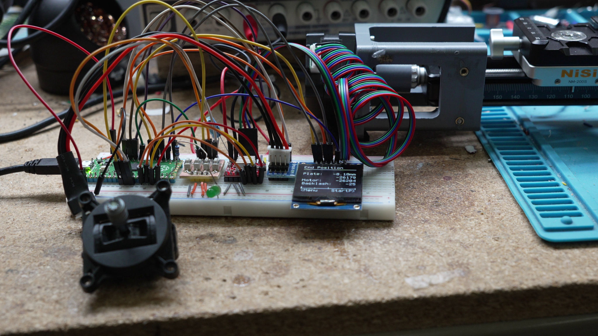
You could transfer the electronics to a perf board [blocked] and be done with this step.
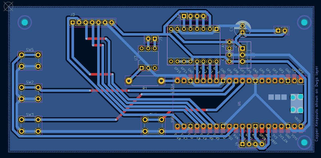
Since I have a 3018 CNC machine, I decided to go a little farther and cut out a PCB:
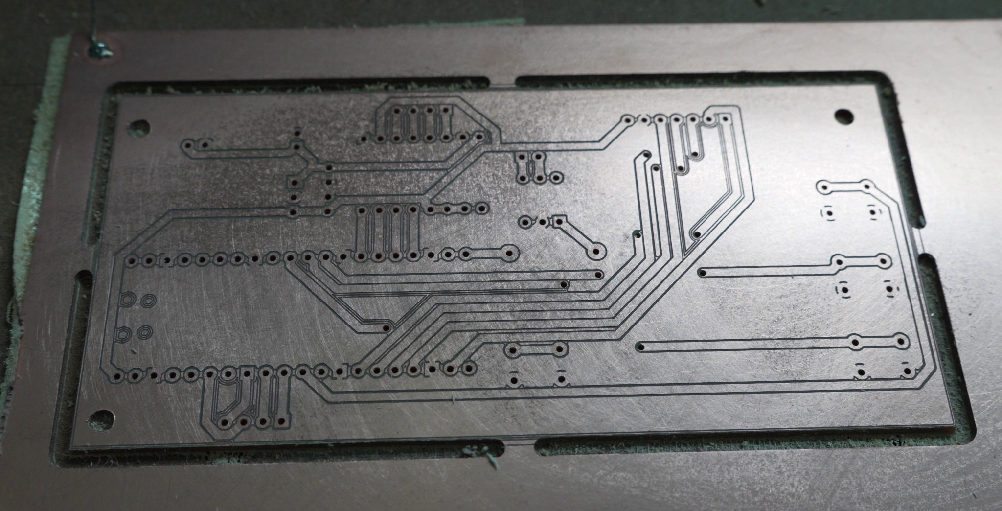
Here is the board flipped over and populated with components:
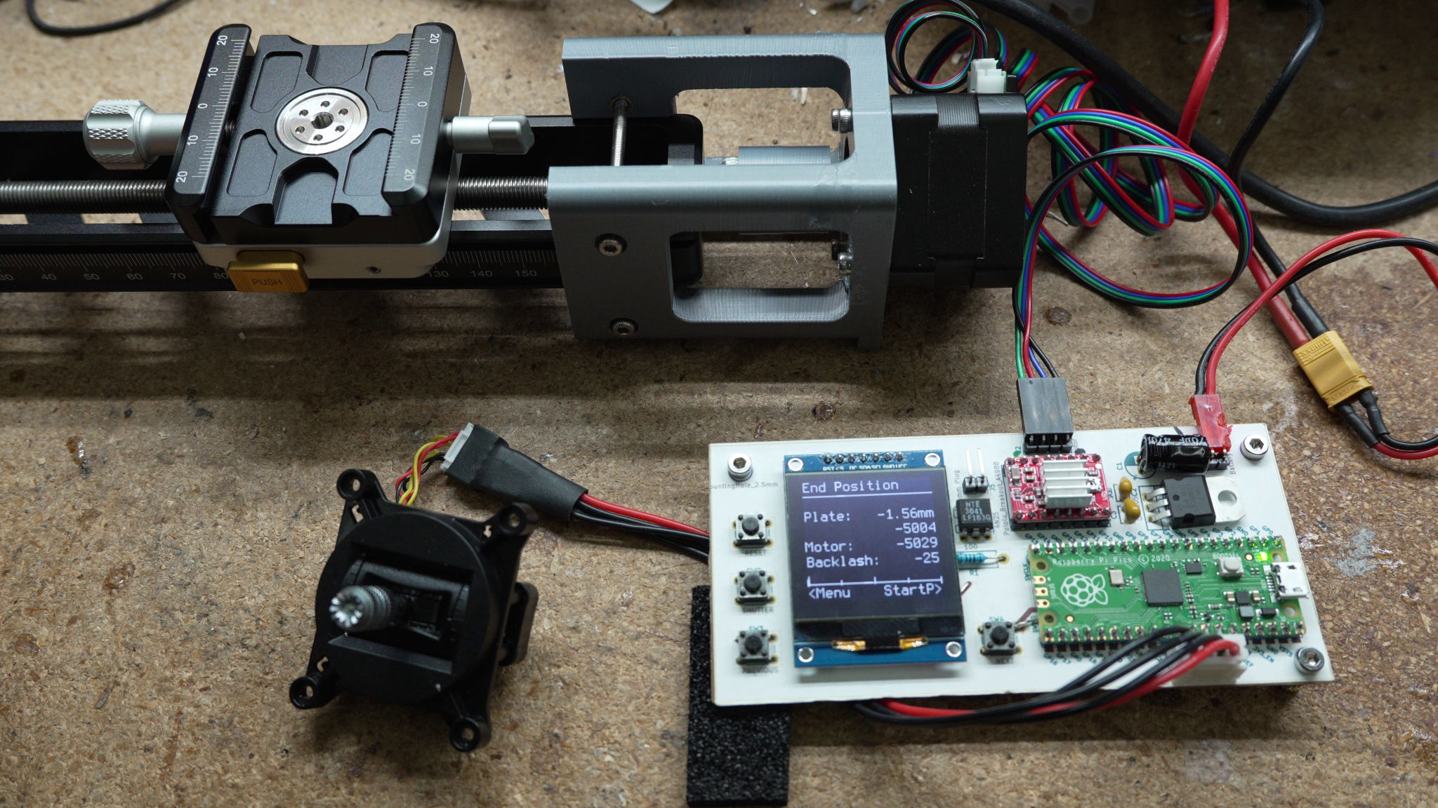
If you want to use a CNC, chemical etch, or order a manufactured board,
you can find the needed files in the motor_rail_kicad/ directory.
Here you have the "easy" option of uploading a precompiled .uf2 file to your
Pico or the "flexible" option of building the binary yourself. Both options are
free.
There are many guides for how to do this, just a Google search away. Here is my version.
BOOTSEL button, plug in the Pico via USBfirmware/macro_rail_automater.uf2 file to the USB driveThere are alternatives you can explore as well:
picotool program which
allows you to load the macro_rail_automater.uf2 file directly. I prefer it.RUN. If you drive it to 0V, it will reset the PICO.
If you do this while holding BOOTSEL, you can upload firmware which is
ergonomically easier and with less USB port wear-and-tear. I
put a switch between RUN and ground (battery negative) whenever I go with a
Pico for this reason (as is done in the schematic above).To start, you'll need a working development environment. I'll point you to the official docs if you are not there yet. I personally prefer following Appendix C "Manually configure your environment" first over the VS Code docs, then add VS Code later so I have both options available.
Once your blinking light project is working, you are nearly done. Here are the command line instructions (use the official Pico docs as a guide for VS Code)
src/ directory../bootstrap.sh. In Windows, you'll need to follow
the steps listed in ./bootstrap.sh which are identical to the official
docs.cd buildmakeAt this point, you'll hopefully have your own macro_rail_automater.uf2 file that you can load
on the your Pico.
The goal is to interface the stepper motor with the macro rail of your choosing. I ended up going with the NM-200s focusing rail which I find sufficient but not amazing. It has some flex which leads to some shifts between photos but the stacking software compensates for this. I might try a cheaper one or potentially DIY one with some steel rods and linear bearings, if I find the time/motivation.
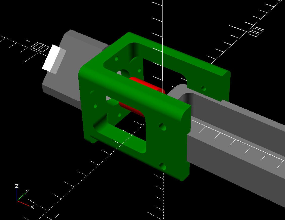
For the route I took, only two printed parts are needed. One interfaces the rail to the motor using a clamping interface:
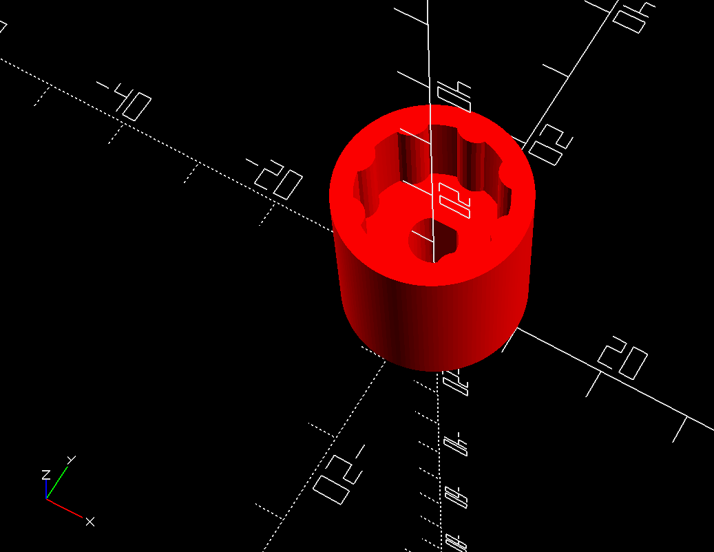
The other printed part interfaces the motor shaft to the finger adjustment knob:
I have included rendered .stl files in the 3d_models/stl
directory that you make be able to use directly if you have a compatible rail.
If you do not have a a matching rail, you can probably make a few tweaks to the
model and have a working result. By using the freely-available OpenSCAD, you can adapt
the clamp interface to various different rails by editing
motor_mount/focus_rail.scad and changing
the following parameters to match your rail:
RAIL_BODY_WIDTH = 37.8;
RAIL_BODY_HEIGHT = 20;
The numbers above (in mm) are for the NM-200s.
The knob interface design should be adaptable to most (but not all) rail
designs. The file to change is motor_mount/knob.scad
with the following variables likely being relevant:
KNOB_DIAMETER = 15.1;
KNOB_INSET_DIAMETER = 13.2;
...
finger_cutout_diameter = 4;
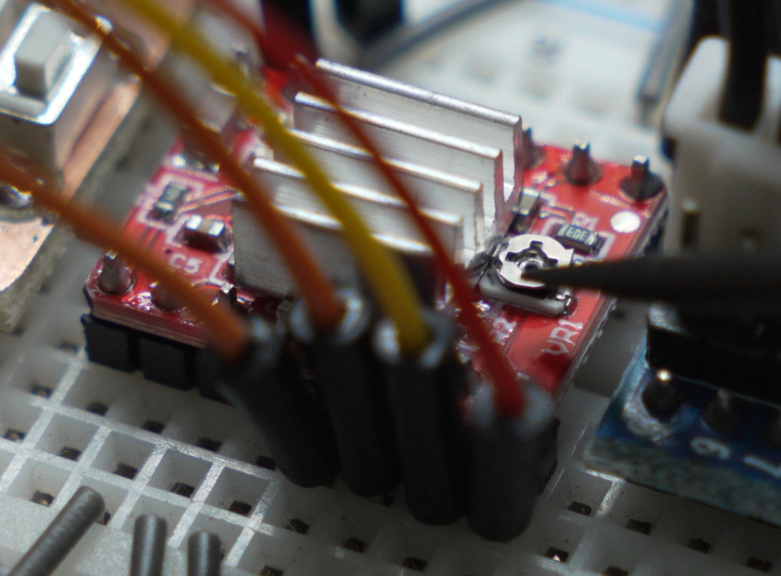
finger_cutout_count = 8;You will need to calibrate your A4988 driver board to set the current properly for your chosen stepper motor. Intructions on how to calibrate are here with alternate instructions here.
If you power on the unit and press the "previous button", you are taken to a menu that lets you chang the following settings:
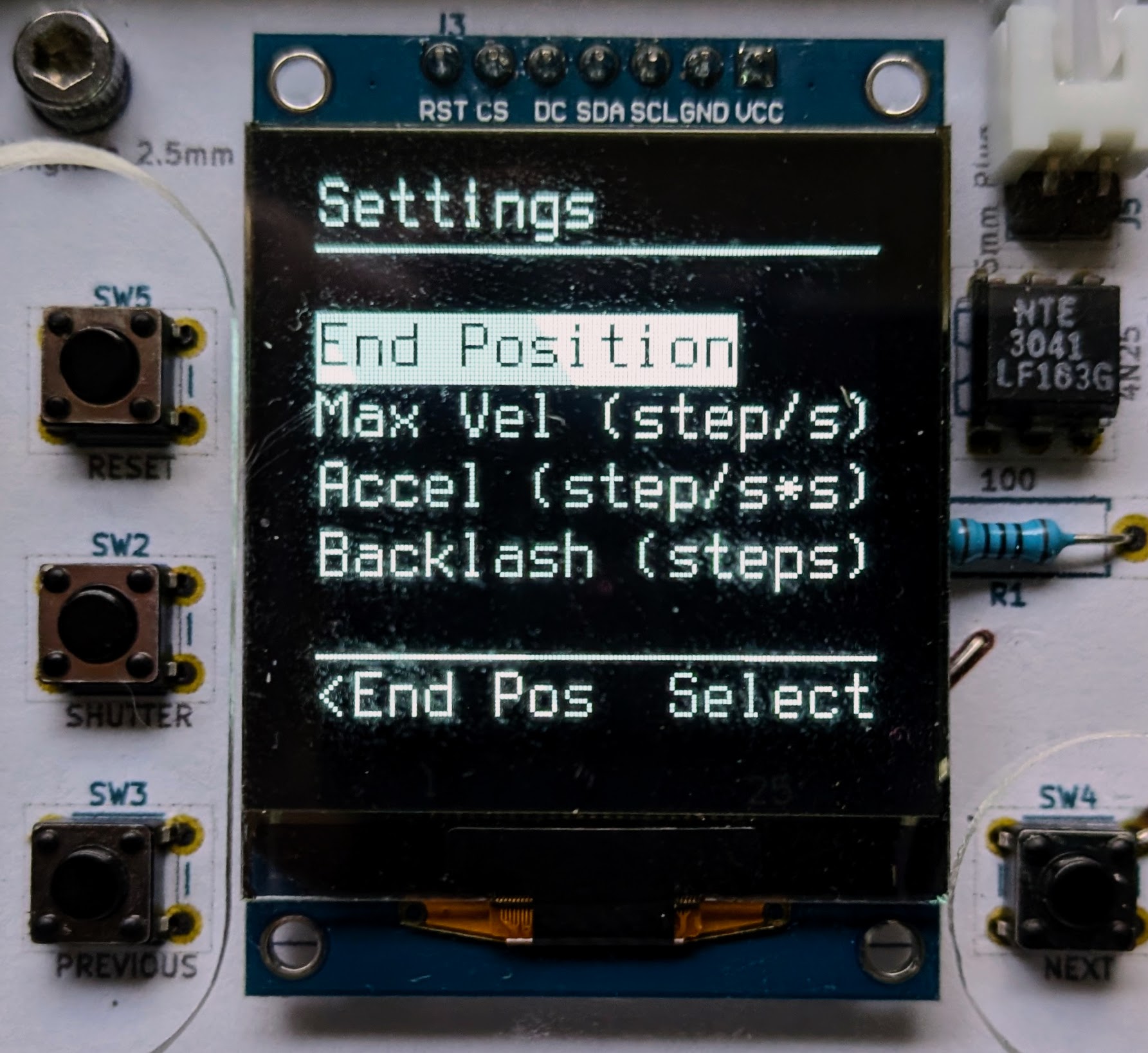
This final menu item relates to both your motors steps/rotation and your rails rotations/mm. The a4988 driver is configured in the schematic above to 16x microstep mode, meaning that 16 steps equal one step on the motor. The formula to use is thus:
motor_steps_per_rotation * 16 / mm_per_rotationFor my case, I'm personally using a 200 steps/rotation stepper motor and a 1 rotation/mm rail, thus my number will be 200 * 16 / 1 = 3200.
In the folder 3d_models/controller, there is a file named controller.scad, which OpenSCAD will render like this:
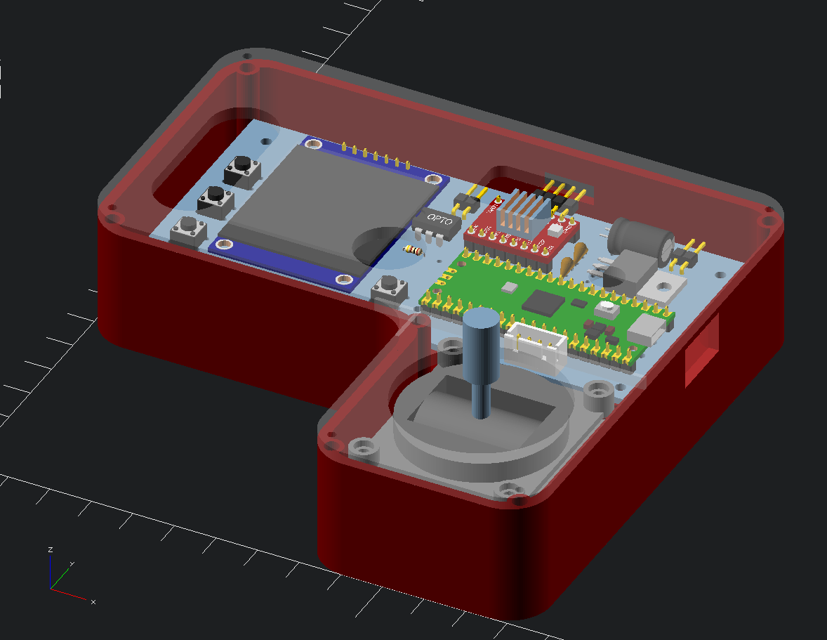
This model is intended for the parts and PCB model that I'm using. If you went with different parts, made a differently-shaped PCB, or do not have a CNC machine for the acrylic cover, you can either try to modify the given design or make a custom one using whatever parts / methods work for you.
If you want to start with an STL file, you can find one at 3d_models/stl/controller.stl
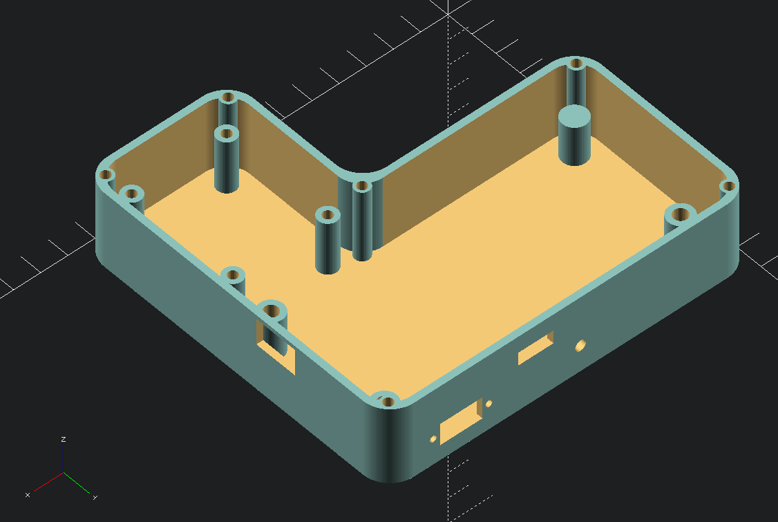
If you want to edit the OpenSCAD model directly, it can be found at
3d_models/controller/controller.scad.
The model is parametric and has many varialbes you can change and experiement
with. The bottom of the file allows you to turn components on and off using th the usual OpenSCAD prefixes of *, ! and //:
// comment out everything but controller for the 3d print model
controller(false);
placed_pcb();
placed_gimbal();
cover();
// comment out everything but this to create a dxf projection
//cover_projection();
The cover_projection() can be used to create a .dxf export for CNC or a laser cut.
Alterrnatively, you can 3D print the cover, likely with some modifications
to allow the screen to be viewed:
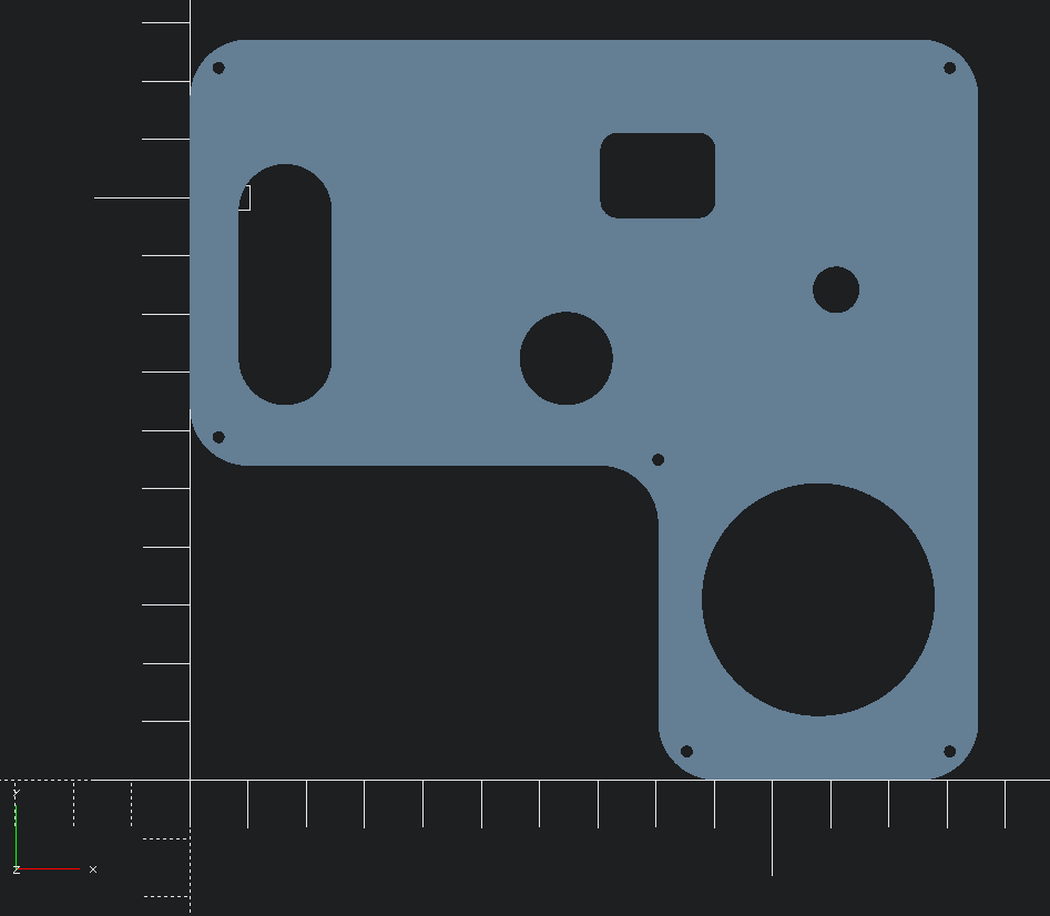
An exported DXF is available at 3d_models/dxf/controller_cover.dxf if you would like to use that as your starting point.
This section talks about the end-to-end experience of using the rail.
You first need to attach the stepper motor to the rail by sliding it on and gently tightening the bolts (don't overdo it). The motor can easily be detached if you don't need it for a given session.`
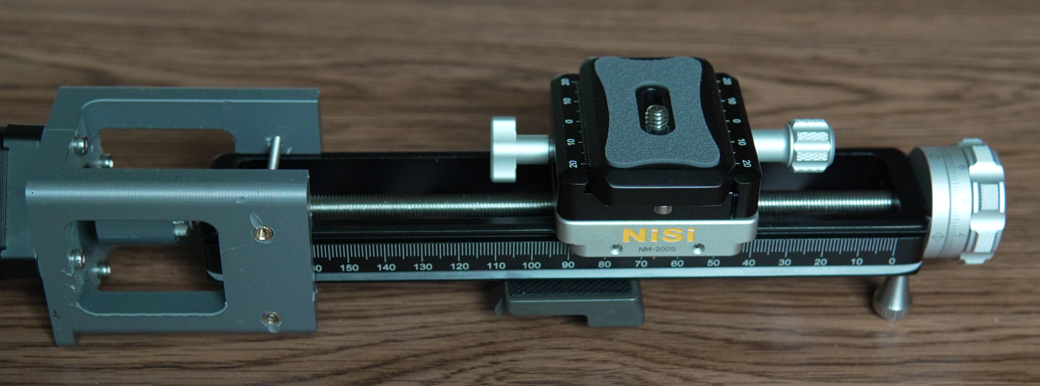
Next line up the camera and target and make sure that nothing is moving.
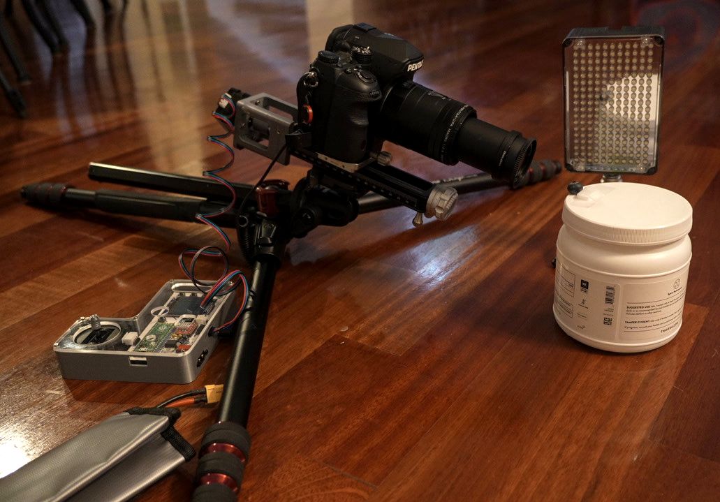
It's good to have a light on your subject to reduce to exposure time and make the light consistent. Where you place the light is an artistic choice but side lighting is a good starting point. Flash is an option but you might need to slow down your process to allow the flash to charge between shots.
You'll want manual everything on your camera, focus, shutter speed, aperture, ISO and white balance. If these parameters change in any of the photos, it can create problems with the stacking software.
I suggest f/5.6, f/8 or f/11 for aperture. Wider apertures will have (possibly not perceptible) sharpness improvements due to less diffraction but you will need to take more images to due to less depth of field.
Power on the focusing rail and use the joystick to find the farthest out point (note you can also find the closest point first, if you prefer).
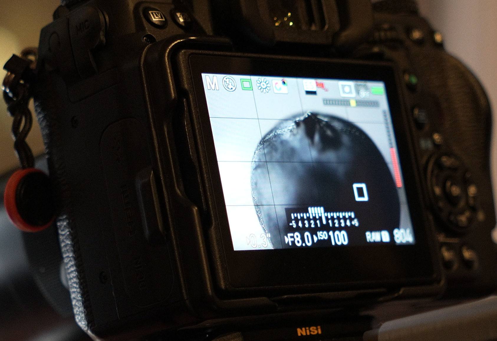
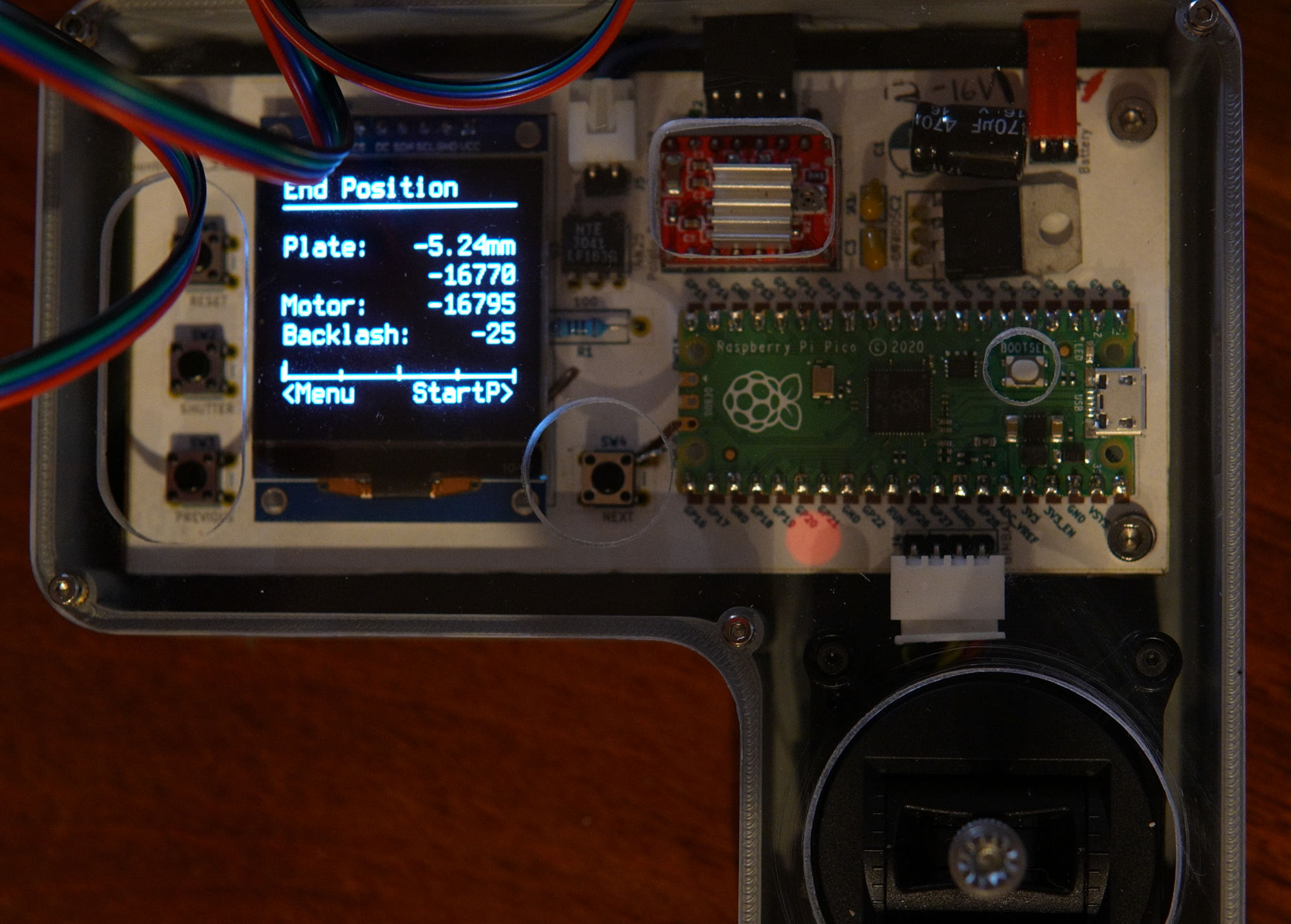
Hit the 'next' button and find the closest point.
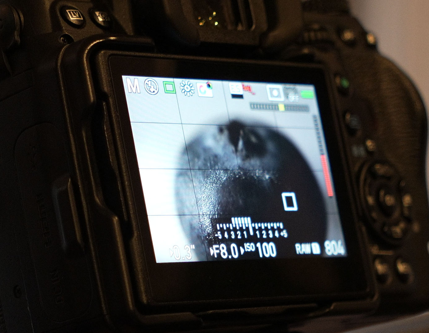
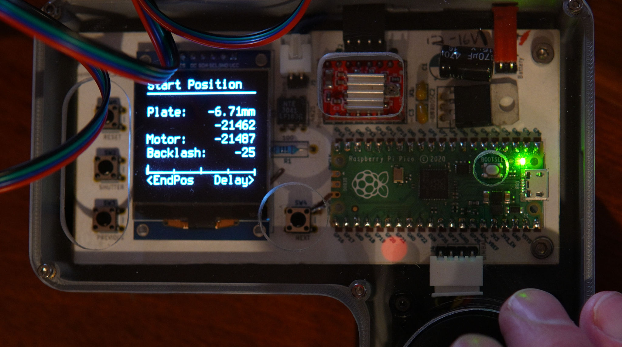
Hit the 'next' button to choose the shot delay. My exposure settings indicate that a photo will take 1/8th of a second to take. You also want to think about how long the camera will take to write the photo to the SD card (most cameras will buffer shots in memory, but maybe not enough). If your camera offers a setting for "electronic shutter", I suggest turning it on as any amount of shutter shock is especially visible during macro work.
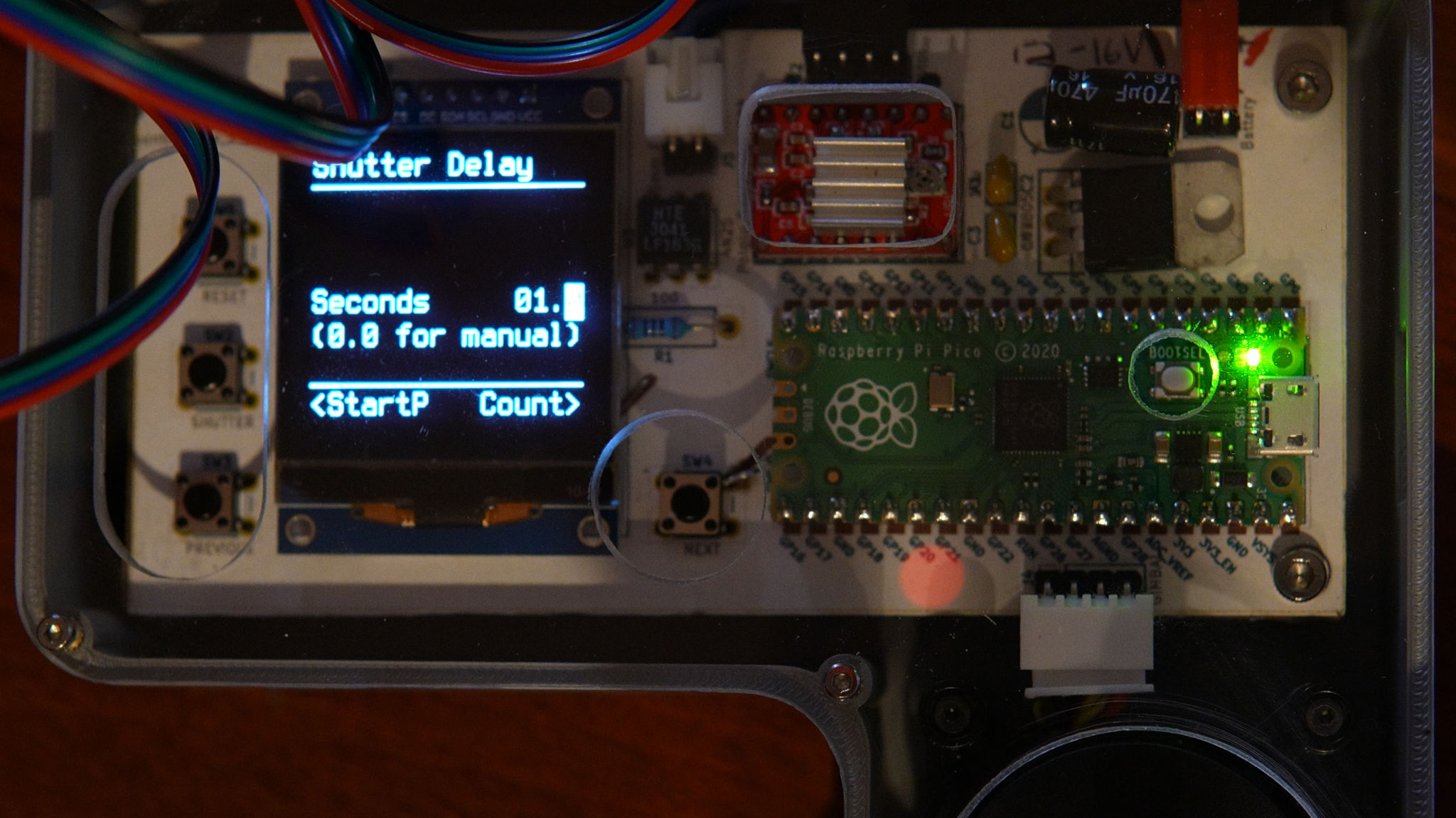
If you don't have the remote shutter working with your camera, you have
the option of choosing 0.0 here. In that case, the rail will pause
after each photo, giving you as much time as you need to manually take
the photo. In this mode, the "next" button is used to continue.
The correct image count depends on many variables:
You'll need to experiment. If you do not know where to begin, I suggest f/8 and 0.2mm and see how it goes (or try this chart).
Hit the 'next' button and choose your shot count
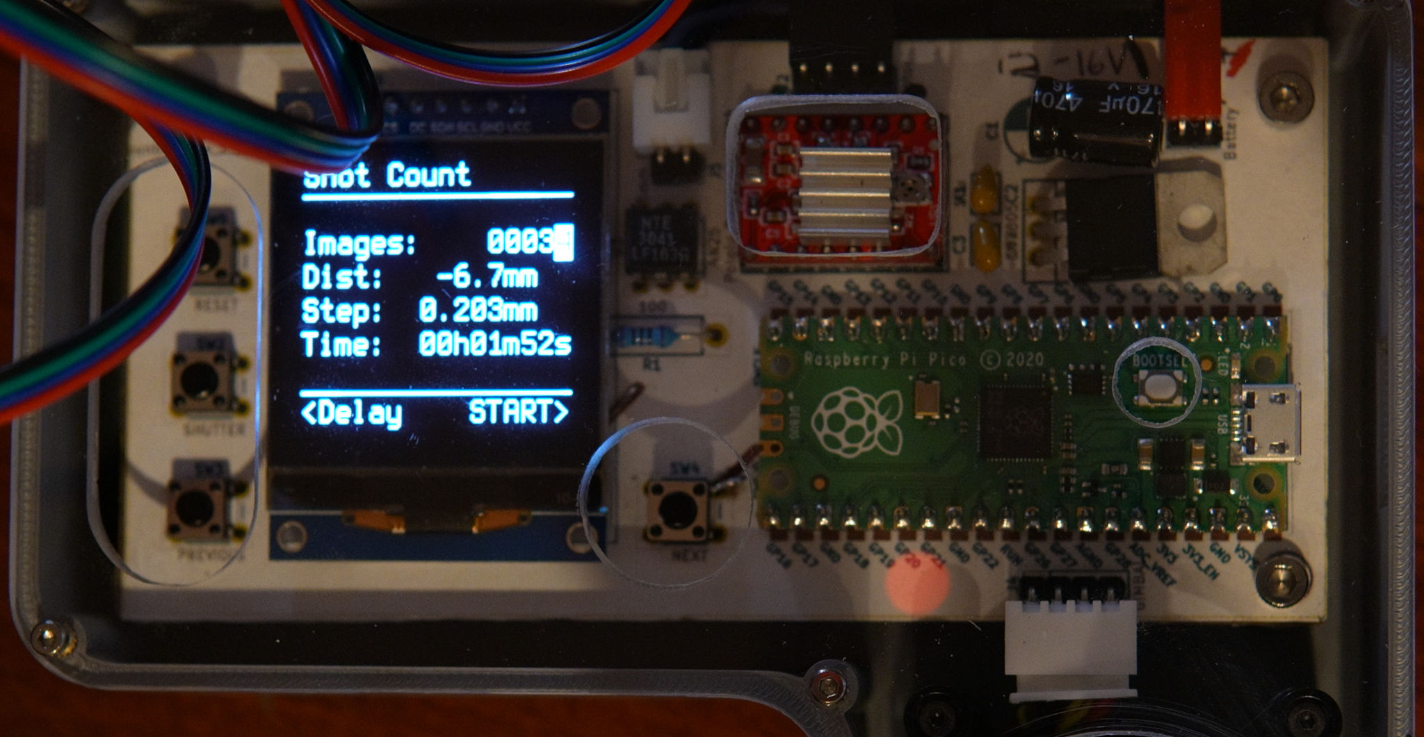
Hit the next button to take all of the photos. You can pause/resume the process
with the next button or cancel it with the back button. If you find a need
to abort everything quickly or just want to start over, you can press the reset
button (I suggest using next/back over reset if the motor is spinning).
When all photos are taken, you have the option of repeating the process in the reverse direction with the 'next' button or starting over with the 'back' button.
I suggest Helicon focus for reasonably priced, turn key software with a free trial period. The software is for mac or windows but I am running it in Linux with Wine and it runs fine.
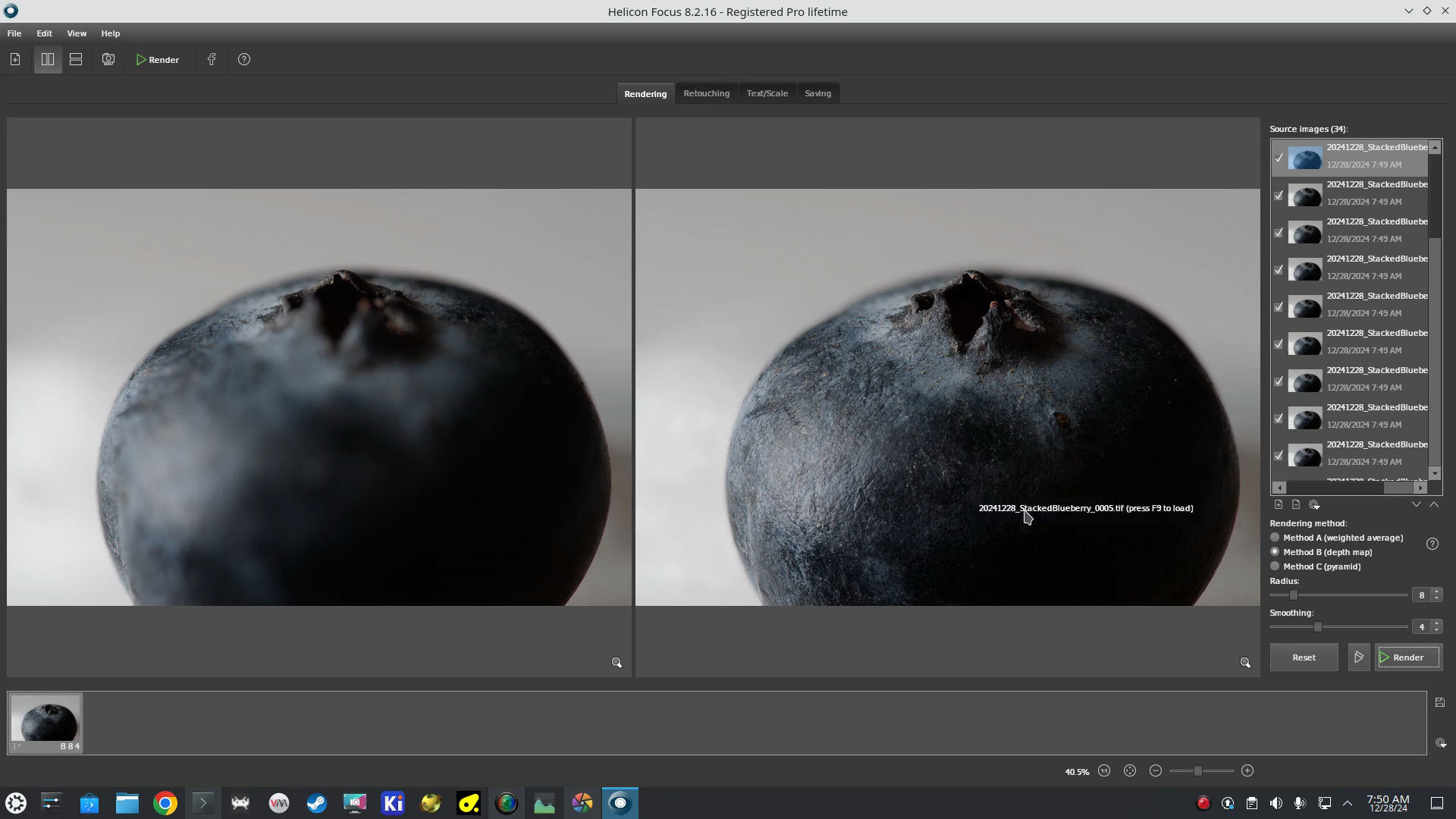
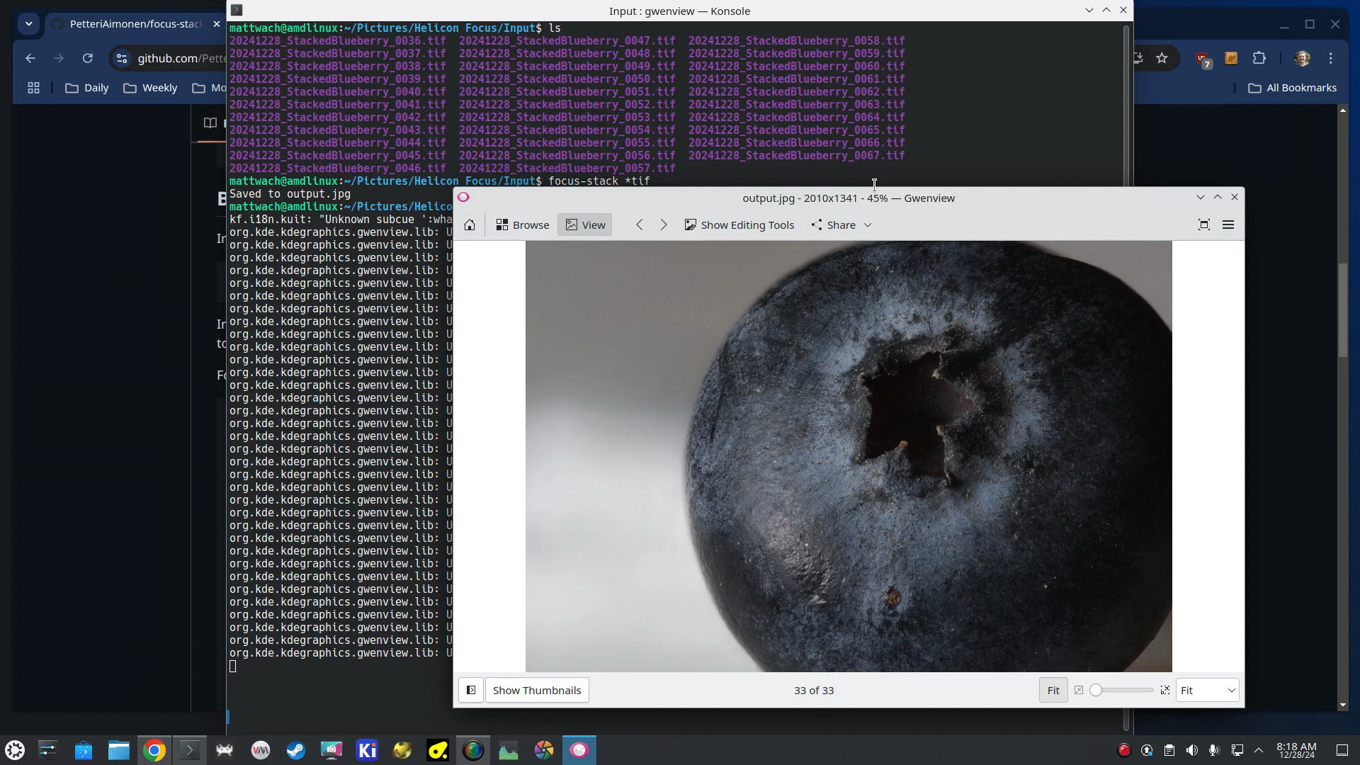
If you want a free/open source solution, check out the focus stack project. The main downside of going this route is that the excellent post-stack retouching features of Helicon are not present, but many people are able to use the software to produce excellent images regardless:
| Qty | Value | Footprint | References |
|---|---|---|---|
| 2 | 10u | Capacitor_THT:C_Disc_D3.8mm_W2.6mm_P2.50mm | C2, C3 |
| 1 | 100 | Resistor_THT:R_Axial_DIN0411_L9.9mm_D3.6mm_P12.70mm_Horizontal | R1 |
| 1 | 128x128 OLED | Matt:OLED_128_128_1.5in | J3 |
| 1 | 2.5mm Plug | Connector_PinHeader_2.54mm:PinHeader_1x02_P2.54mm_Vertical | J5 |
| 1 | 470u | Capacitor_THT:CP_Radial_D6.3mm_P2.50mm | C1 |
| 1 | 4N25 | Package_DIP:DIP-6_W7.62mm | U3 |
| 1 | Battery | Connector_PinHeader_2.54mm:PinHeader_1x02_P2.54mm_Vertical | J1 |
| 1 | GIMBAL | Connector_PinHeader_2.54mm:PinHeader_1x04_P2.54mm_Vertical | J4 |
| 1 | LM7805 | Package_TO_SOT_THT:TO-220-3_Vertical | U2 |
| 1 | Motor | Connector_PinHeader_2.54mm:PinHeader_1x04_P2.54mm_Vertical | J2 |
| 1 | NEXT | Button_Switch_THT:SW_PUSH_6mm_H4.3mm | SW4 |
| 1 | PREVIOUS | Button_Switch_THT:SW_PUSH_6mm_H4.3mm | SW3 |
| 1 | Pico | RP-Pico:RPi_Pico_SMD_TH | U1 |
| 1 | Pololu_Breakout_A4988 | Module:Pololu_Breakout-16_15.2x20.3mm | A1 |
| 1 | RESET | Button_Switch_THT:SW_PUSH_6mm_H4.3mm | SW5 |
| 1 | SHUTTER | Button_Switch_THT:SW_PUSH_6mm_H4.3mm | SW2 |
The 17 most common of 20 parts.
tvlad1234/pillScopePlus
Oscilloscope based around the STM32F401 Black Pill and a color LCD screen

PhysicsDptAngers/polyUAnalog
Open source, analog and polyphonic synthesizer

thebiguno/microcontroller-projects
A home for a bunch of microcontroller projects which don't warrant their own repos.

wntrblm/Big_Honking_Button
A simple Eurorack sampler and performance module in a silly package.


tebl/C64-Modulator-Replacement
A simple modulator replacement for Commodore 64s with "longboards", complements my Lumafix version as well adding an audio connector for second SID.


It measures 119.4 × 57.2 mm and has 2 copper layers, 1.6 mm thick.
20 parts, built around the LM7805. The full list of its parts is on this page, with links to each part's symbol and footprint where PCBKit's library has them.
From the mattwach/motorized_macro_rail repository on GitHub, at the commit this page was made from: the board is macro_rail_kicad/macro_rail_kicad.kicad_pcb and its schematic macro_rail_kicad/macro_rail_kicad.kicad_sch. PCBKit opens the board in the browser, with nothing to install.
Its repository states no licence, so its author keeps all rights: ask mattwach before reusing the design.