
4 layers99 × 53.3 mm
PSLab
fossasia/pslab-hardware
PSLab Hardware Design and Schematics https://pslab.io
199 parts1.7kApache-2.0

 mattvenn/laser-controller
legend 32 ex, coherent C series laser controller
Laser control is an open-source printed circuit board by mattvenn, from the mattvenn/laser-controller repository on GitHub. It is a 2-layer board of 53 × 41 mm with 16 parts on 18 nets, routed with 156 tracks and 6 vias.
It is built around the WS2812B. Its parts include 3 resistors, 3 diodes, 1 capacitor, 1 transistor and 1 switch.
ESP8266
2 channel relay & driver
RFID reader
ws2812 RGB status light
Neither Epilog or Coherent were willing to share the DSUB 25 pinout that controls the Coherent C Series laser model 1138402-AA.
Searching for the DSUB 25 format, only references to ILDA were found.
A board that connects straight through 2 x DSUB 25 was designed in Kicad and milled
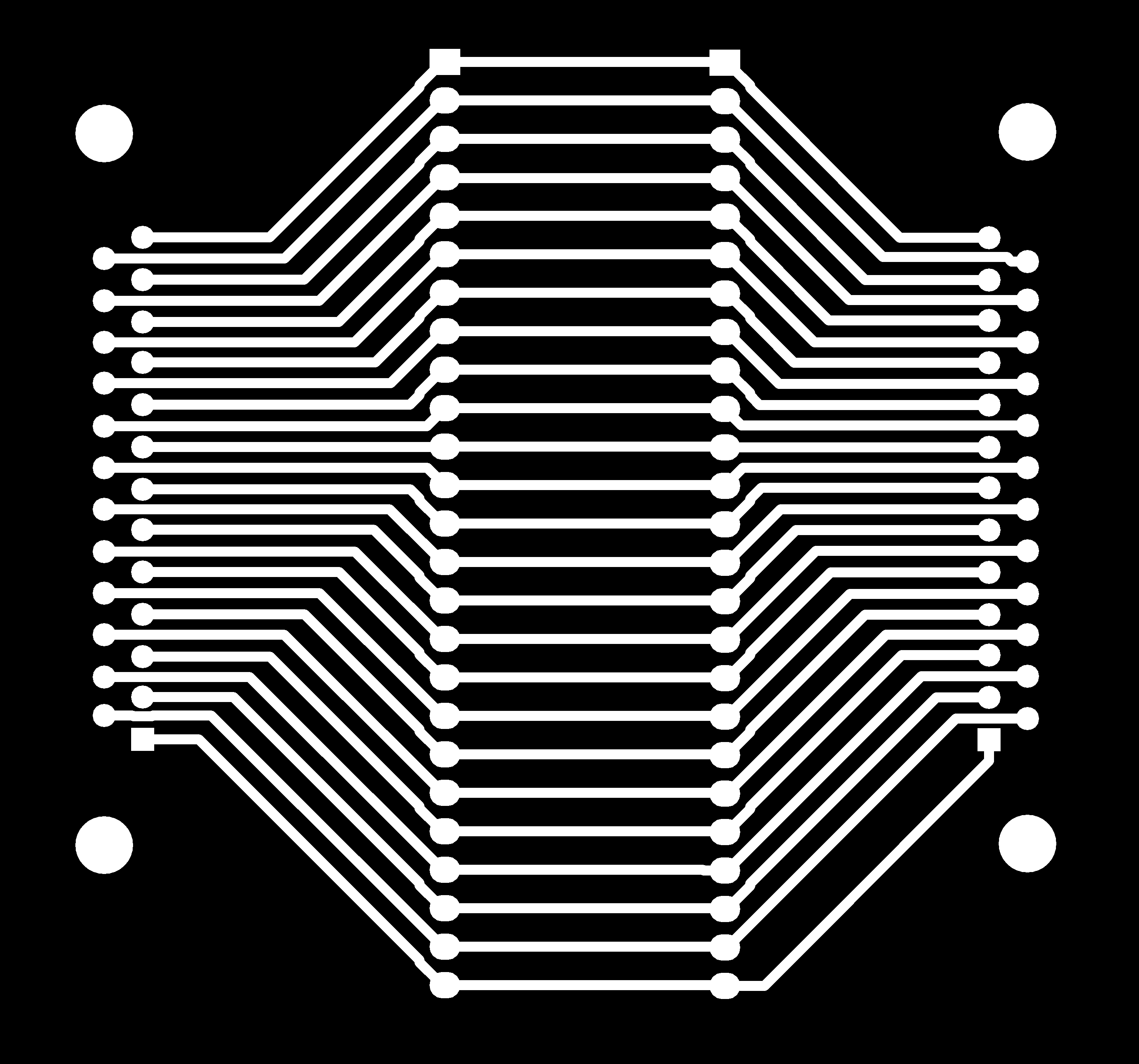
After finding system ground, all pins were tested with laser on and off:
| Pin | Laser On | Laser Off |
|---|---|---|
| 1 | 0 | 0 |
| 2 | 0 | 0 |
| 3 | 5 | 5 |
| 4 | 0 | 0 |
| 5 | 0 | 0 |
| 6 | 5 | 5 |
| 7 | 5->0 | 0 |
| 8 | 5 | 5 |
| 9 | 5 | 5 |
| 10 | 5 | 5 |
| 11 | 5 | 5 |
| 12 | 5 | 5 |
| 13 | 0 | 0 |
| 14 | 5 | 5 |
| 15 | 5 | 5 |
| 16 | GND | GND |
| 17 | 0 | 0 |
| 18 | 0 | 0 |
| 19 | 0 | 0 |
| 20 | 0->5 | 5 |
| 21 | 0 | 0 |
| 22 | 5 | 5 |
| 23 | 5 | 5 |
| 24 | 5 | 5 |
| 25 | 15 | 15 |
Only pins 7 & 20 seemed to have any change when lasing. Also thought that they would be a differential signal. Cracking out the scope gave these results for rastering, lasing at 50% power and 100% power.
Scope channel 1 is pin 7, channel 2 is 20.
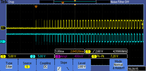
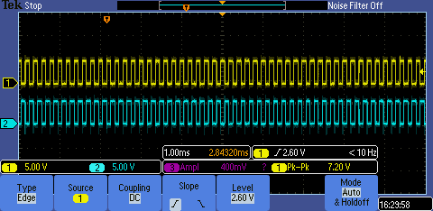
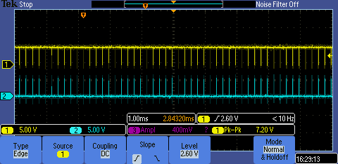
Breaking connection to either pin 7 or 20 made no difference, only breaking both lines stopped the laser.
Also tested was breaking pin 4 as ILDA showed that as being the interlock signal, it made no difference.
| Qty | Value | Footprint | References |
|---|---|---|---|
| 2 | 10k | Resistors_ThroughHole:Resistor_Horizontal_RM15mm | r1, r2 |
| 2 | CONN_01X08 | Pin_Headers:Pin_Header_Straight_1x08 | laser1, rfid1 |
| 2 | D | Diodes_ThroughHole:Diode_DO-41_SOD81_Horizontal_RM10 | D1, D2 |
| 1 | 330r | Resistors_ThroughHole:Resistor_Horizontal_RM15mm | R1 |
| 1 | CONN_01X14 | Pin_Headers:Pin_Header_Straight_1x14 | esp-con1 |
| 1 | CP | Capacitors_ThroughHole:C_Radial_D5_L6_P2.5 | C1 |
| 1 | Q_NPN_EBC | Housings_TO-92:TO-92_Inline_Wide | Q1 |
| 1 | RELAY_2RT | fp:relay | K1 |
| 1 | ws2812b | fp:WS2812B | led1 |
The 12 most common of 16 parts.
It measures 53 × 41 mm and has 2 copper layers, 1.6 mm thick.
16 parts, built around the WS2812B. The full list of its parts is on this page, with links to each part's symbol and footprint where PCBKit's library has them.
From the mattvenn/laser-controller repository on GitHub, at the commit this page was made from: the board is control-board/laser-control.kicad_pcb. PCBKit opens the board in the browser, with nothing to install.
Its repository states no licence, so its author keeps all rights: ask mattvenn before reusing the design.
fossasia/pslab-hardware
PSLab Hardware Design and Schematics https://pslab.io

FrameworkComputer/ExpansionCards
Reference designs and documentation to create Expansion Cards for the Framework Laptop


PrintersForAnts/Micron
If you want to purchase full kits there are 3 available (Kits are slowly updating to R1 hardware just make sure to double check the included hardware in your kit and if you have any questions reach out in the discord)


