2 layers30 × 61.3 mm

 matthijskooijman/FtdiTranslator
Voltage level converter for FTDI-style 6-pin serial connections
FtdiTranslator is an open-source printed circuit board by matthijskooijman, from the matthijskooijman/FtdiTranslator repository on GitHub. It is a 2-layer board of 43.2 × 17.8 mm with 45 parts on 14 nets, routed with 111 tracks and 4 vias.
Its parts include 6 resistors, 3 transistors, 2 capacitors, 2 connectors and 1 IC. It belongs with the interfaces and adapters boards of this library.
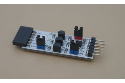
This repository contains the PCB design for an serial level translator board. It is intended to be used with a 6-pin USB-to-serial adapter that used the "FTDI" pinout, which is commonly used for Arduino boards as well (e.g. by the Pro Mini).
When using such an adapter, the voltage levels must typically be matched with the target board. This is fairly easy for standard 5V and 3.3V boards (by having two adapters, or having an adapter that can switch between both voltages), but when the target runs on a non-standard voltage (e.g. powered by batteries), you need to insert a converter board in between.
This board provides such conversion on the TX, RX and DTR lines.
The translator circuit is pretty much copied from this Adafruit board (except with a different transistor). Also see AN10441 from NXP that explains how the translator works.
The repository contains the KiCad design files for the board, under "Releases" in github I also have pre-generated gerber files to use. I have a few spare boards from my own order, which you can order through tindie.
The components to completely build this design, are:
Depending on your needs, some parts can be left out:
This design is copyrighted by Matthijs Kooijman and distributed under the CERN Open Hardware License, version 1.2 or above. See LICENSE.txt for the full text of the license.
| Qty | Value | Footprint | References |
|---|---|---|---|
| 6 | 10k | Resistors_SMD:R_0805_HandSoldering | R1, R2, R3, R4, R5, R6 |
| 3 | 2N7000 | TO_SOT_Packages_THT:TO-92_Inline_Narrow_Oval | Q1, Q2, Q3 |
| 3 | Jumper_NO_Small | Pin_Headers:Pin_Header_Straight_1x02_Pitch2.54mm | JP1, JP2, JP3 |
| 2 | 1uF | Capacitors_SMD:C_0805_HandSoldering | C1, C2 |
| 2 | oshw_logo | Footprints:oshw | G***, G*** |
| 1 | FTDI-DEVICE | Pin_Headers:Pin_Header_Angled_1x06_Pitch2.54mm | P1 |
| 1 | FTDI-HOST | Pin_Headers:Pin_Header_Angled_1x06_Pitch2.54mm | P2 |
| 1 | MCP1700 | TO_SOT_Packages_SMD:SOT89-3_Housing_Handsoldering | U1 |
The 19 most common of 45 parts.

imchipwood/dumbpad
Simple 4x4 numpad with rotary encoder. Powered by QMK via ATmega32u4 Pro Micro


makeo/PicoLoader
A cheap and easy to install modchip for the Nintendo GameCube!


peterkrull/quad
Firmware, hardware and documentation for my autonomous quad copter project

tebl/RC6502-Apple-1-Replica
An expandable SBC-version of the Apple 1 computer, easy to get started with and lot of cool stuff that can be added to it!

It measures 43.2 × 17.8 mm and has 2 copper layers, 1.6 mm thick.
45 parts. The full list of its parts is on this page, with links to each part's symbol and footprint where PCBKit's library has them.
From the matthijskooijman/FtdiTranslator repository on GitHub, at the commit this page was made from: the board is FtdiTranslator.kicad_pcb. PCBKit opens the board in the browser, with nothing to install.
Its repository states no licence, so its author keeps all rights: ask matthijskooijman before reusing the design.