Skip to the content
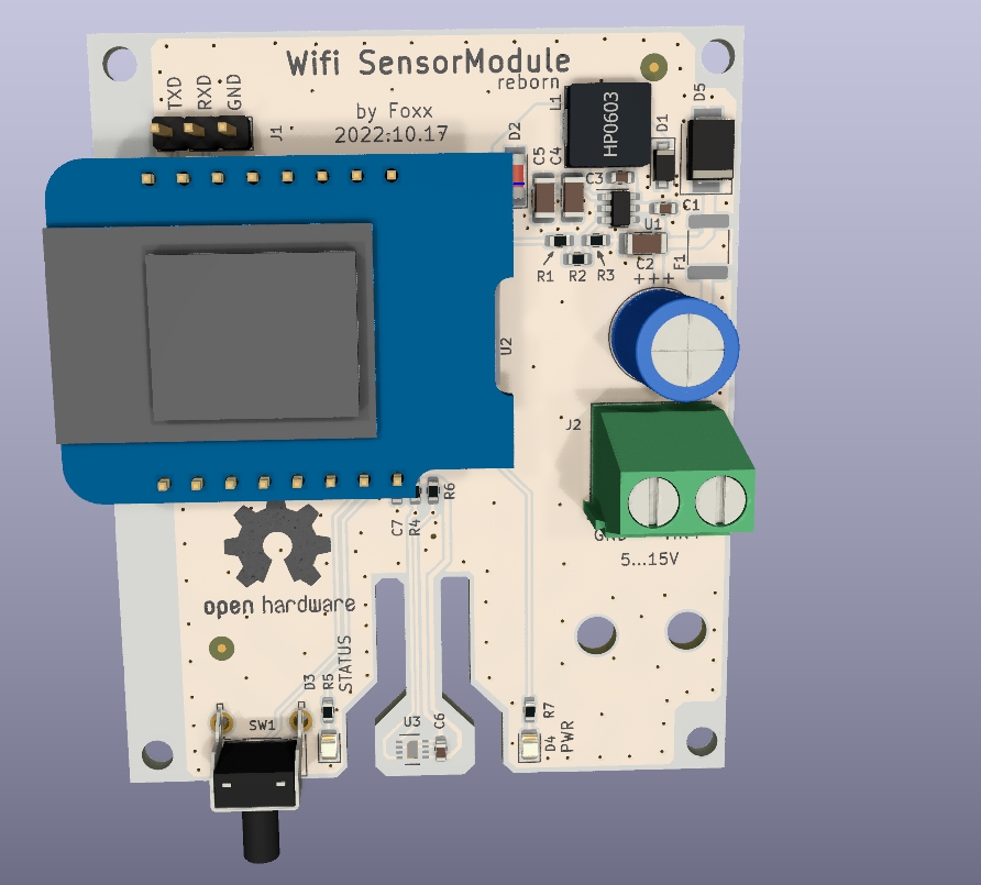
2 layers53.3 × 64.4 mmWifi homesensor, the printed circuit board in 3D

Quick and dirty ESP8266 based thermo and humidity meter for ESPhome

Size
53.3 × 64.4 mm
Copper layers
2
Thickness
1.6 mm
Parts
33
Nets
26
Pads
89
Tracks, vias
165, 168
Pours
3
Routed
Yes
KiCad
KiCad 6 (file 20211014)
Created
8 Oct 2022
Updated
17 Oct 2022

Overview

Wifi homesensor is an open-source printed circuit board by masterfoxxhu, from the masterfoxxhu/wifi_homesensor repository on GitHub, published under the GPL-3.0 licence. It is a 2-layer board of 53.3 × 64.4 mm with 33 parts on 26 nets, routed with 165 tracks and 168 vias.

It is built around the WEMOS D1 MINI, MCP16301-E/CH and SHT31-DIS-F, with the LL4148, SM6T15A and SS26FL among its other parts. Its parts include 8 capacitors, 8 resistors, 5 diodes, 3 ICs and 2 connectors. It belongs with the radio and wireless boards and the ESP8266 boards of this library.

Main components

6

README

README.md

wifi_homesensor

Quick and dirty ESP8266 based thermo and humidity meter for ESPhome

Based around a Wemos D1 mini module, using SHT31 sensor, and a MCP16301 DCDC converter.
Enclosure PA62W

A render of the board.
The sensor is located on the bottom of the board to minimise heat pickup from the rest of the board. There is a vent near the sensor on the enclosure.

Alt text

Parts

33
QtyValueFootprintReferences
4100nFCapacitor_SMD:C_0603_1608MetricC1, C3, C6, C7
44.7kResistor_SMD:R_0603_1608MetricR4, R5, R6, R7
310uF 25VCapacitor_SMD:C_1206_3216MetricC2, C4, C5
210kResistor_SMD:R_0603_1608MetricR3, R8
2FiducialFiducial:Fiducial_0.75mm_Mask2.25mmFID1, FID2
2LEDLED_SMD:LED_0805_2012MetricD3, D4
11.2kResistor_SMD:R_0603_1608MetricR2
1100mAFuse:Fuse_1812_4532MetricF1
1100uF 35VCapacitor_THT:C_Radial_D8.0mm_H11.5mm_P3.50mmC8
115uHmasterfoxx_footprint:inductor_6_5x6_5L1
130kResistor_SMD:R_0603_1608MetricR1
1AK500/2TerminalBlock_Phoenix:TerminalBlock_Phoenix_MKDS-1,5-2-5.08_1x02_P5.08mm_HorizontalJ2
1KiCad-Logo2_8mm_SilkScreenSymbol:KiCad-Logo2_8mm_SilkScreenLOGO2
1LL4148Diode_SMD:D_MiniMELFD2
1Logo_Open_Hardware_SmallSymbol:OSHW-Logo2_14.6x12mm_SilkScreenLOGO1
1MCP16301Package_TO_SOT_SMD:SOT-23-6U1
1Pinhdr 3x2.5Connector_PinHeader_2.54mm:PinHeader_1x03_P2.54mm_VerticalJ1
1SHT31-DISSensor_Humidity:Sensirion_DFN-8-1EP_2.5x2.5mm_P0.5mm_EP1.1x1.7mmU3
1SM6T15ADiode_SMD:D_SMBD5
1SS26FLDiode_SMD:D_SOD-123FD1
1SW_PushButton_Switch_THT:SW_Tactile_SPST_Angled_PTS645Vx83-2LFSSW1
1WeMos_D1_miniModule:WEMOS_D1_mini_lightU2

Similar boards

  • 2 layers99 × 99 mmCurrent Limiter, the printed circuit board in 3D

    Current Limiter

    kwiecinski/BMS-and-offgrid-photovoltaic-management-system

    Project contains BMS for lead-acid batteries and ESP-based board used to pull information from EASUN offgrid inverter, energy meters and sensors.

    68 parts3MIT
  • 4 layers76.7 × 44.5 mmMotCtrl, the printed circuit board in 3D

    MotCtrl

    osannolik/MotCtrl

    Inverter for brushless motors

    162 parts65GPL-3.0
  • 4 layers173 × 67 mmPCB MINIBOX, the printed circuit board in 3D

    PCB MINIBOX

    stan-one/hydrobox_pcb

    PCB files and schematic for the hydrobox project

    68 partsMIT
  • 2 layers83.8 × 80 mmMosogep, the printed circuit board in 3D

    Mosogep

    simonyiszk/mosogep-sch-reboot

    Project reboot

    80 parts2
  • 4 layers53 × 39 mmAvclan mockingboard rounded, the printed circuit board in 3D

    Avclan mockingboard rounded

    halleysfifthinc/AVCLAN-Mockingboard

    Emulate a CD Changer on a Toyota AVC LAN network

    43 parts65GPL-3.0
  • 6 layers170 × 170 mmHILTOP Motherboard, the printed circuit board in 3D

    HILTOP Motherboard

    devtank-ltd/kicad_hiltop_motherboard

    HILTOP Motherboard

    801 parts1
  • 2 layers100 × 100 mmPCB modelo, the printed circuit board in 3D

    PCB modelo

    Matyy38/erc-rover-EyP

    Documentación del subsistema de Electrónica y Potencia del rover del European Rover Challenge (IEEE ITBA I+D). Dos frentes: el rover final (40 kg, bus de 24 V, swerve de 4 ruedas) y el modelo a escala, que es un…

    76 parts1
  • 4 layers80 × 80 mmPICO RS485, the printed circuit board in 3D

    PICO RS485

    mortens-lab/PICO_RS485

    Raspberry Pi Pico with RS485 interface and sensors

    61 parts6

Questions

How big is the Wifi homesensor PCB?

It measures 53.3 × 64.4 mm and has 2 copper layers, 1.6 mm thick.

What parts does the Wifi homesensor use?

33 parts, built around the WEMOS D1 MINI, MCP16301-E/CH, SHT31-DIS-F and LL4148. The full list of its parts is on this page, with links to each part's symbol and footprint where PCBKit's library has them.

Where can I download the Wifi homesensor KiCad files?

From the masterfoxxhu/wifi_homesensor repository on GitHub, at the commit this page was made from: the board is Wifi_homesensor.kicad_pcb and its schematic Wifi_homesensor.kicad_sch. PCBKit opens the board in the browser, with nothing to install.

Can I use the Wifi homesensor design in my own project?

Its repository publishes it under the GPL-3.0 licence: you may reuse it on that licence's terms (keep the author's notice, and for a copyleft licence share your changes alike).