2 layers28.3 × 39.8 mm
LevelShifter
gusmanb/logicanalyzer
24 channel, 100Msps logic analyzer hardware and software
21 parts5.1kGPL-3.0
 MasonSmithTech/Pad.IX
Pad.IX is a macropad project for the Hack Club Stardance Challange.
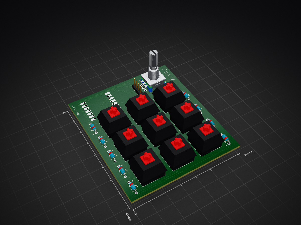
PadIXFinal is an open-source printed circuit board by MasonSmithTech, from the MasonSmithTech/Pad.IX repository on GitHub. It is a 2-layer board of 71.4 × 81 mm with 21 parts on 23 nets, routed with 151 tracks and 0 vias.
Its parts include 10 switches, 9 diodes, 1 IC and 1 connector. It belongs with the keyboards and input boards of this library.
this project is a spot where the code, schematics, 3d models, and other files related to the Hack Club Stardance "HackPad" project are located, with my iteration named "Pad.IX" since it has nine keys.
The Pad.IX is a nine key macro pad with an encoder and OLED screen, with future hopes of implementing VIA for custom keymapping.
The case was modeled inside of OnShape (A new tool for me) and renders (as seen above) were created inside of fusion 360. The case features a top piece which holds the switches and pcb, and a bottom piece to protect the electronics, with the two parts being bolted together with M3 bolts and heat press inserts. The case was somewhat influenced by the OZO Keyboards Skeleton Keyboard Case, but mainly it is just an interesting looking open shell design that appeared in my brain on the bus home from school!
the schematic and PCB are created using KiCad and LOTS of google.
schematic:
PCB:
This hackpad uses QMK firmware for everything.
the rotary encoder changes volume. press to mute The 9 keys currently act as ma number pad The OLED is a status display of sorts (mainly says "Pad.IX" tho) Hopefully VIA support will be added once I actually build the thing irl
Thats pretty much it the firmware was pretty confusing to make so idk what to say
- 9x cherry MX switches
- 9x DSA Keycaps (not required)
- 1x 0.91" 128x32 OLED Display
- 1x Seed XIAO RP2040
- 1x EC11 Rotary Encoder
- 1x Custom designed and manufactured pcb
- 1x 3d printed top housing
- 1x 3d printed bottom housing
- 4x M3 heatpress inserts
- 4x M3x16mm SHCS Bolts
- 10x 1N4148 DO-35 Diodes- QMK MSYS
- Fusion 360
- KiCad 9.0
- Onshape
- Visual Studio Code
- File Explorer
- Thanks!Thanks to the people at Hack Club this was an amazing experience! This is my first Hack Club build but I am looking forward to doing so much more in the future! Also thanks to google cuz this was VERY confusing!
| Qty | Value | Footprint | References |
|---|---|---|---|
| 9 | 1N914 | Diode_THT:D_DO-35_SOD27_P7.62mm_Horizontal | D1, D2, D3, D4, D5, D6, D7, D8, D9 |
| 9 | SW_Push | Button_Switch_Keyboard:SW_Cherry_MX_1.00u_PCB | SW1, SW2, SW3, SW4, SW5, SW6, SW7, SW8, SW9 |
| 1 | Conn_01x04_Pin | Connector_PinHeader_2.54mm:PinHeader_1x04_P2.54mm_Vertical | J1 |
| 1 | MOUDLE-SEEEDUINO-XIAO | footprints:XIAO-Generic-Hybrid-14P-2.54-21X17.8MM | U1 |
| 1 | RotaryEncoder_Switch | Rotary_Encoder:RotaryEncoder_Alps_EC11E-Switch_Vertical_H20mm | SW10 |
gusmanb/logicanalyzer
24 channel, 100Msps logic analyzer hardware and software

mntmn/amiga2000-gfxcard
MNT VA2000, an Open Source Amiga 2/3/4000 Graphics Card (Zorro II/III), written in Verilog


hackclub/OnBoard
💡 Join 1,000 teenagers and make your first PCB with a $100 grant!

drandyhaas/KiCadRoutingTools
A set of Python/Rust tools to aid routing in KiCad

Arrow-air/project-quiver
Project Quiver documentation, designs, and project artifacts.


It measures 71.4 × 81 mm and has 2 copper layers, 1.6 mm thick.
21 parts. The full list of its parts is on this page, with links to each part's symbol and footprint where PCBKit's library has them.
From the MasonSmithTech/Pad.IX repository on GitHub, at the commit this page was made from: the board is PCB/PadIXFinal.kicad_pcb and its schematic PCB/PadIXFinal.kicad_sch. PCBKit opens the board in the browser, with nothing to install.
Its repository states no licence, so its author keeps all rights: ask MasonSmithTech before reusing the design.