4 layers

 mash/cupwarmer
目標は 15W 級の Qi EPP 受電と、12V・約12W のヒーター。保温と軽い再加熱を狙って開発しています。
Heater is an open-source printed circuit board by mash, from the mash/cupwarmer repository on GitHub. It is a 2-layer board of 55 × 55 mm with 2 parts on 4 nets.
Qi ワイヤレス給電で飲み物を温かく保つ、カップウォーマーの自作プロジェクトです。カップの下に置く小さなデバイスに、Qi 受電回路・ヒーター・温度保護をまとめています。
目標は 15W 級の Qi EPP 受電と、12V・約12W のヒーター。保温と軽い再加熱を狙って開発しています。
| 部分 | v1 の設計 |
|---|---|
| Qi 受電 | STMicroelectronics STWLC38JRM。外部 MCU を使わず、IC の自律動作を利用 |
| 制御 PCB | 直径50mm、4層、厚さ1.6mm |
| ヒーター | 直径約55mm のシリコーン flexible heater。12Ω、100kΩ NTC 内蔵 |
| 温度保護 | heater 内蔵 NTC を STWLC38 の RX_NTC に接続。独立した70°C サーモスタット F1 をヒーターに直列接続 |
| メンテナンス | I²C service header から状態確認・NVM 設定 |
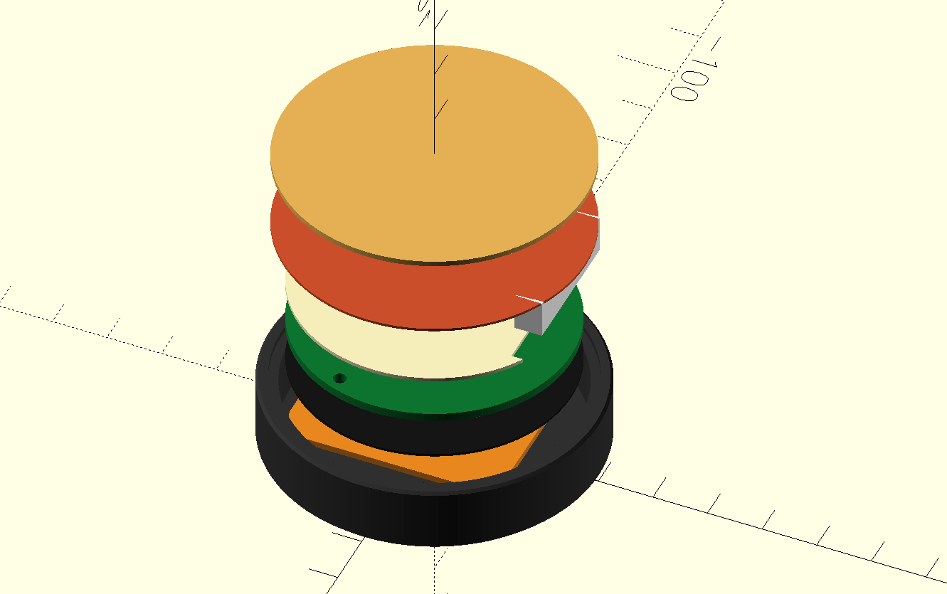
| 筐体 | 外径60mm の bottom tray。OpenSCAD で設計 |
カップ側から cup contact pad → flexible heater → insulation → PCB → ferrite → RX coil → bottom tray の順に重ねます。aluminum spreader は比較候補で、初回評価では省く構成です。
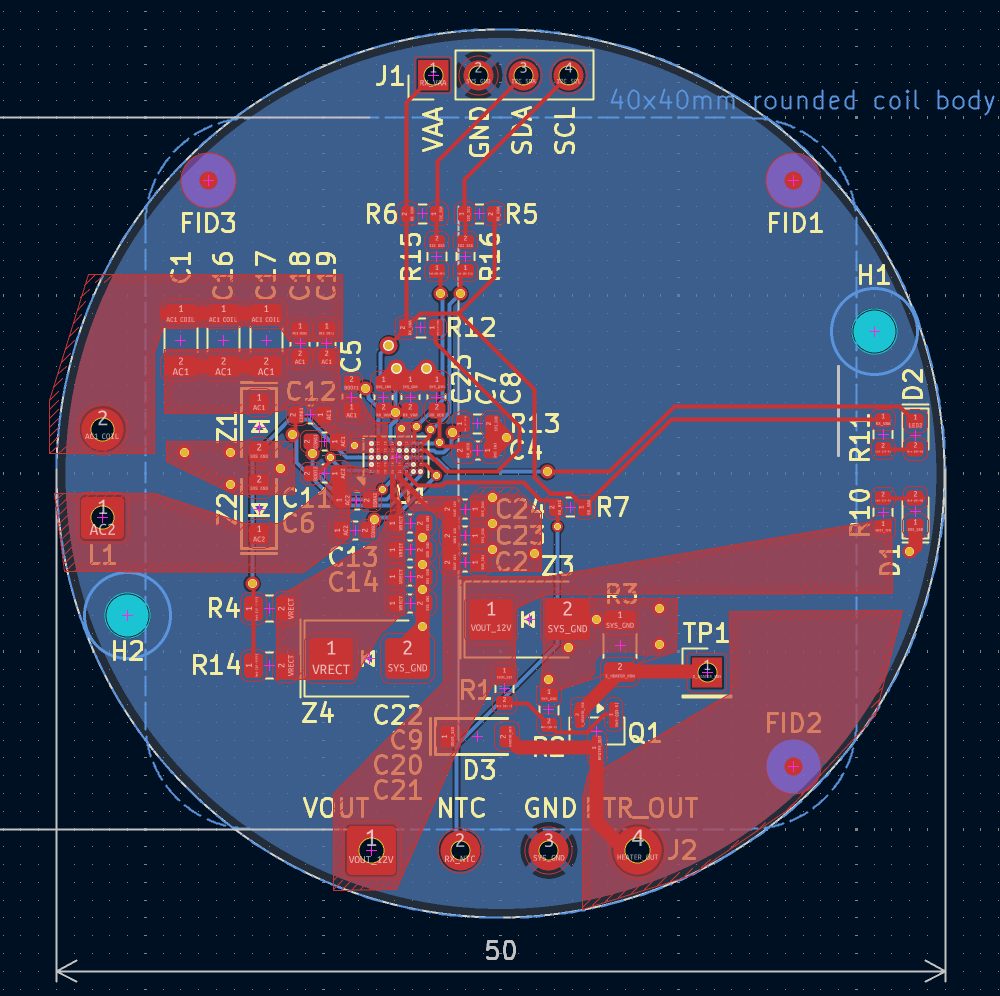
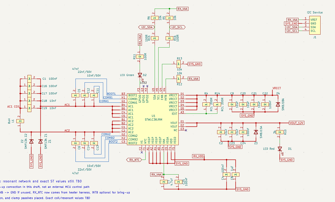
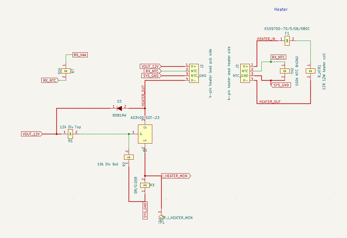
v1 は受電出力が有効な間、ヒーターを連続通電する設計です。PWM による温度調整は実装していません。
画像は設計の概要を示すスクリーンショットです。製作・変更時は KiCad ソース と 機構ソース を参照してください。機構図には比較候補の部材も含まれます。
動作・温度保護を評価中の試作です。
確認済み:
未検証:
直近の DA04 試験はヒーター電源線を切り離した状態で行っています。12V・約12W は設計目標であり、達成済みの性能ではありません。試験条件と結果は DA04 を含む NVM 設定の記録 にまとめています。
| 場所 | 内容 |
|---|---|
| docs/design-notes.md | 設計判断と評価方針 |
| hardware/kicad/ | 回路図・PCB・部品ライブラリ |
| hardware/bom/ | 部品表と実装発注用 BOM |
| hardware/fab/ | Gerber・部品配置などの製造出力 |
| hardware/mechanical/ | OpenSCAD モデル・STL・機構設計ノート |
| hardware/firmware/stwlc38/ | ST 参照ファームウェア・設定と取得元 |
| hardware/test/ | 試験記録・設定候補・I²C ツール・オフラインテスト |
| wiki/ | 部品・規格・参考資料の調査ノート |
詳しい機構構成は 機構設計ノート、NVM 書き込みの手順と制約は STWLC38 programming を参照してください。
| Qty | Value | Footprint | References |
|---|---|---|---|
| 1 | 100k NTC 0603 | Heater:NTCPads | NTC1 |
| 1 | Heater and NTC leads | Heater:LeadoutPads | J1 |

hzeller/rpi-rgb-led-matrix
Controlling up to three chains of 64x64, 32x32, 16x32 or similar RGB LED displays using Raspberry Pi GPIO


adamws/kicad-kbplacer
KiCad plugin for automatic keyboard's key placement and routing

Luos-io/luos_engine
Open-source and real-time orchestrator for cyber-physical-systems, to easily design, test and deploy embedded applications and digital twins.

NVNTLabs/switch2-SDEX2M2
Micro SD Express to M.2 NVME Adapter for Nintendo Switch 2

BlueSCSI/BlueSCSI-v2
BlueSCSI v2/Ultra - an open source, open hardware, SCSI emulator using the Pi Pico PR2040 and Pico 2 RP2350

ohmtech-rdi/eurorack-blocks
Software to Hardware Prototyping for Eurorack using C++, Max/Gen~ or Faust

It measures 55 × 55 mm and has 2 copper layers, 0.2 mm thick.
2 parts. The full list of its parts is on this page, with links to each part's symbol and footprint where PCBKit's library has them.
From the mash/cupwarmer repository on GitHub, at the commit this page was made from: the board is hardware/kicad/heater/heater.kicad_pcb and its schematic hardware/kicad/cupwarmer-hw/cupwarmer-hw.kicad_sch. PCBKit opens the board in the browser, with nothing to install.
Its repository states no licence, so its author keeps all rights: ask mash before reusing the design.