2 layers52.8 × 71.8 mm
ESPBoosted
schoolllex/ESPBoosted
A custom, feature-rich ESP32-WROOM-32 development board featuring built-in environmental sensors, power management, and expansion interfaces.
51 parts
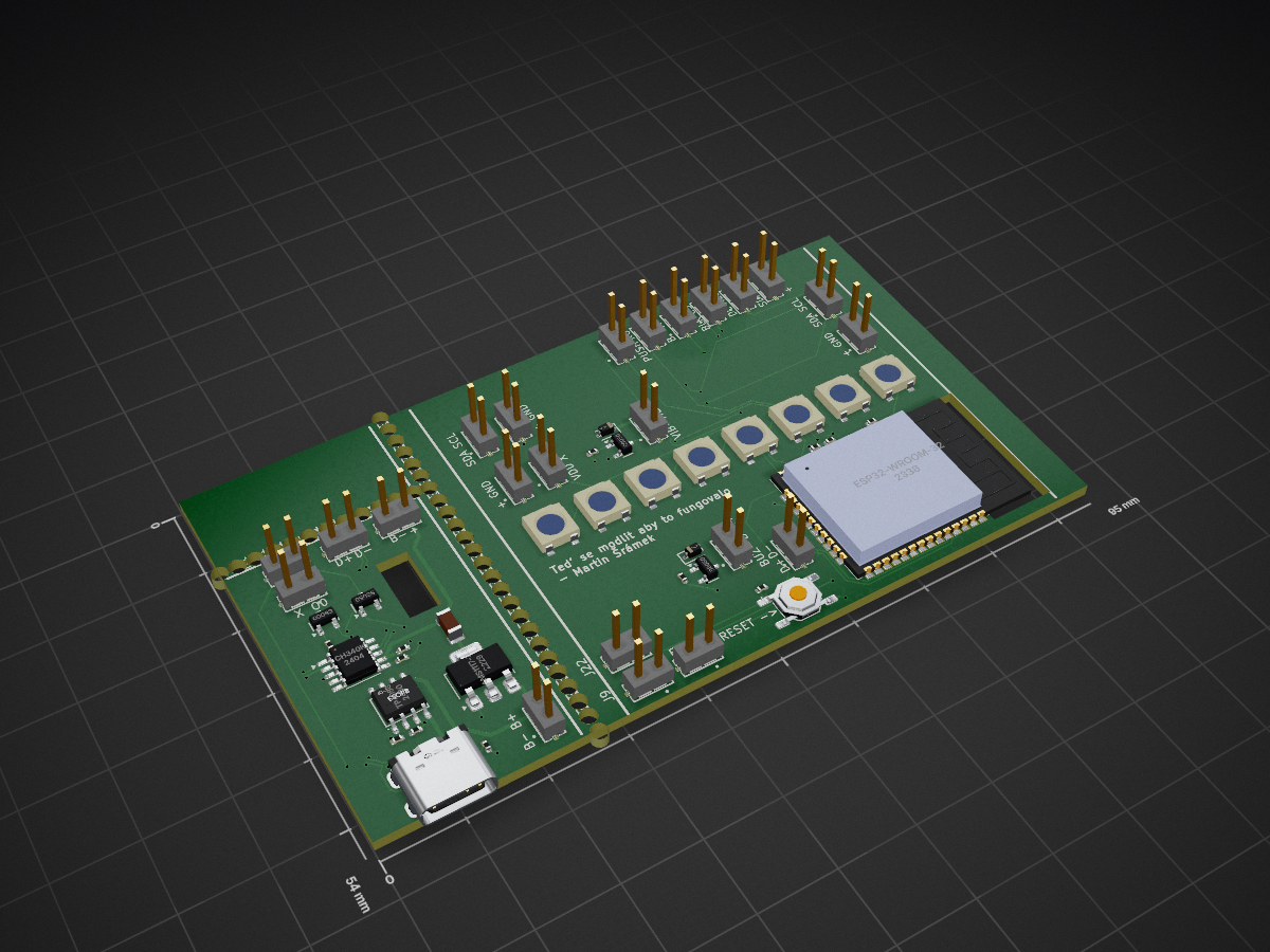
 martinsram3k/Node-Smart-Clock
The project blends modern electronics with premium natural materials:
Esp smart clock is an open-source printed circuit board by martinsram3k, from the martinsram3k/Node-Smart-Clock repository on GitHub. It is a 2-layer board of 95 × 54 mm with 96 parts on 81 nets, routed with 445 tracks and 84 vias.
It is built around the ESP32-WROOM-32D-N4, CH340K and AMS1117-3.3, with the TP4056, MTLW-101-05-G-D-150 and WS2812B among its other parts. Its parts include 24 connectors, 10 resistors, 10 diodes, 4 ICs and 4 transistors. It belongs with the lEDs and displays boards and the ESP32 boards of this library.


Node Smart Clock is an open-source, multi-functional desk clock powered by the ESP32-WROOM-32D-N4. It is designed as a central hub for makers, entrepreneurs, and crypto enthusiasts, combining advanced environmental sensing with real-time data tracking.
The project blends modern electronics with premium natural materials:
| Designator | LCSC # | Value / Description | Qty | Unit Price | Ext. Price | Note |
|---|---|---|---|---|---|---|
| U1 | C473012 | ESP32-WROOM-32D-N4 | 1 | $3.78790 | $3.78790 | Main MCU |
| U4 | C15255 | PCF8563T (RTC) | 1 | $0.32000 | $0.32000 | Not in export, estimated |
| U5 | C6186 | AMS1117-3.3 (LDO) | 5 | $0.17350 | $0.86750 | Voltage regulator |
| U6 | C16581 | TP4056 (Charger) | 5 | $0.17840 | $0.89200 | Battery charging |
| D1-D8 | C22461793 | WS2812B (RGB LED) | 8 | $0.03840 | $0.30720 | Addressable LEDs |
| D10-D12 | C2128 | 1N4148WS (Diode) | 4 | $0.02100 | $0.08400 | Power OR Logic |
| Q1-Q4 | C318884 | S8050 (Transistor) | 10 | $0.01250 | $0.12500 | Reset/Motor/Buzzer |
| J1 | C2927039 | USB-C 16-pin | 1 | $0.23190 | $0.23190 | Power/Data |
| BT1 | C70381 | Battery Holder CR1220 | 1 | $0.13840 | $0.13840 | RTC Backup |
| C1, C2, C6 | C1525 | 100nF (0402) | 100 | $0.00130 | $0.13000 | Minimal order is 100pcs |
| C3, C4, C5 | C13585 | 10uF (1206) | 10 | $0.02700 | $0.27000 | Power decoupling |
| x | x | 2.4 Inch TFT Display | 1 | $5.90000 | $5.90000 | Display |
| x | x | H7BC ENS160+AHT21 | 1 | $7.95000 | $7.95000 | Temp and co2 sensor |
| x | x | TTP223 | 1 | $0.07000 | $0.07000 | Touch sensor |
| x | x | BH1750 | 1 | $2.49000 | $2.49000 | Ambient light sensor |
| x | x | Brass Copper Embed Insert Nut | 8 | $0.04000 | $0.32000 | M3xL4xOD4.2 |
Download sheet for production: Google sheets.

This project is fully Open-Source.
If you like the Node Smart Clock, there are several ways you can support the development:
Your backing helps us continue developing new open-source features and high-quality hardware for the community.
License: MIT – Feel free to share, modify, and build!
| Qty | Value | Footprint | References |
|---|---|---|---|
| 34 | MountingHole | MountingHole:MountingHole_2.1mm | H1, H1, H1, H1, H1, H1, H1, H1, H1, H1, H1, H1, H1, H1, H1, H1 +18 |
| 23 | MTLW-101-05-G-D-150 | footprints:SAMTEC_MTLW-101-05-G-D-150 | J2, J10, J11, J12, J13, J14, J15, J16, J17, J18, J19, J20, J21, J22, J23, J24 +7 |
| 8 | WS2812B | PCM_JLCPCB:LED_WS2812B_PLCC4_5.0x5.0mm_P3.2mm | D1, D3, D4, D5, D6, D7, D8, D9 |
| 6 | , , , , , | ||
| 4 | 10kΩ | PCM_JLCPCB:R_0402 | R1, R2, R12, R13 |
| 4 | S8050 | PCM_JLCPCB:Q_SOT-23 | Q1, Q2, Q3, Q4 |
| 3 | 1.2kΩ | PCM_JLCPCB:R_0402 | R6, R7, R8 |
| 2 | 100nF | PCM_JLCPCB:C_0402 | C1, C2 |
| 2 | 1N4148WS | PCM_JLCPCB:D_SOD-323 | D2, D10 |
| 2 | 5.1kΩ | PCM_JLCPCB:R_0402 | R4, R5 |
| 1 | 100kΩ | PCM_JLCPCB:R_0402 | R3 |
| 1 | 10uF | PCM_JLCPCB:C_1206 | C4 |
| 1 | AMS1117-3.3 | Package_TO_SOT_SMD:SOT-223-3_TabPin2 | U2 |
| 1 | CH340K | Package_SO:SSOP-10-1EP_3.9x4.9mm_P1mm_EP2.1x3.3mm | U8 |
| 1 | Connector, USB-TYPE-C-16P | PCM_JLCPCB:TYPE-C-SMD_HX-TYPE-C-16PIN | J1 |
| 1 | ESP32-WROOM-32D-N4 | martin:MODULE_ESP32-WROOM-32D-N4 | U1 |
| 1 | TP4056 | PCM_JLCPCB:ESOP-8_L4.9-W3.9-P1.27-LS6.0-BL-EP | U3 |
| 1 | Tactile Button, 160gf | PCM_JLCPCB:SW-SMD_4P-L5.1-W5.1-P3.70-LS6.5-TL-2 | S1 |
It measures 95 × 54 mm and has 2 copper layers, 1.6 mm thick.
96 parts, built around the ESP32-WROOM-32D-N4, CH340K, AMS1117-3.3 and TP4056. The full list of its parts is on this page, with links to each part's symbol and footprint where PCBKit's library has them.
From the martinsram3k/Node-Smart-Clock repository on GitHub, at the commit this page was made from: the board is pcb/esp_smart_clock/esp_smart_clock-backups/esp_smart_clock-2026-01-01_143557/esp_smart_clock.kicad_pcb and its schematic pcb/esp_smart_clock/CR1220-2 /CR1220-2 .kicad_sch. PCBKit opens the board in the browser, with nothing to install.
Its repository states no licence, so its author keeps all rights: ask martinsram3k before reusing the design.
schoolllex/ESPBoosted
A custom, feature-rich ESP32-WROOM-32 development board featuring built-in environmental sensors, power management, and expansion interfaces.

Sagaz0501/esp32-drone
PCB ESP32 quadcopter: KiCad hardware + Madgwick IMU firmware + WiFi web UI

freezweb/de.freezweb.heizungssteuerung
Dieses Verzeichnis enthaelt den KiCad-Startentwurf fuer die dezentrale Pumpengruppen-Platine:

Circuit-Digest/MLX90640-Thermal-Camera
An Open Source Thermal Imaging IR camera that you can build yourserlf

Abhey-05/Thermal-Camera
Thermal Camera A compact, low-cost thermal imaging solution built for diagnostic, repair, and monitoring applications in electronics, industrial safety, and embedded systems.


dharahaas23/ESP32-Smart-Watch
A round, wrist-worn smart watch built around the ESP32-WROOM-32, with heart-rate sensing, a circular color display, USB-C charging, and a custom PCB antenna — designed as part of the #30DaysOfPCB progression from…