2 layers28.1 × 22.1 mm
Dual edge wake
nbolton/esp8266-dual-edge-wake
Open source module for ESP8266, wakes MCU from deep sleep when a sensor value changes
17 parts3

 markgajevskis/Kiel_506
BLDC sine wave controller shield for Arduino UNO
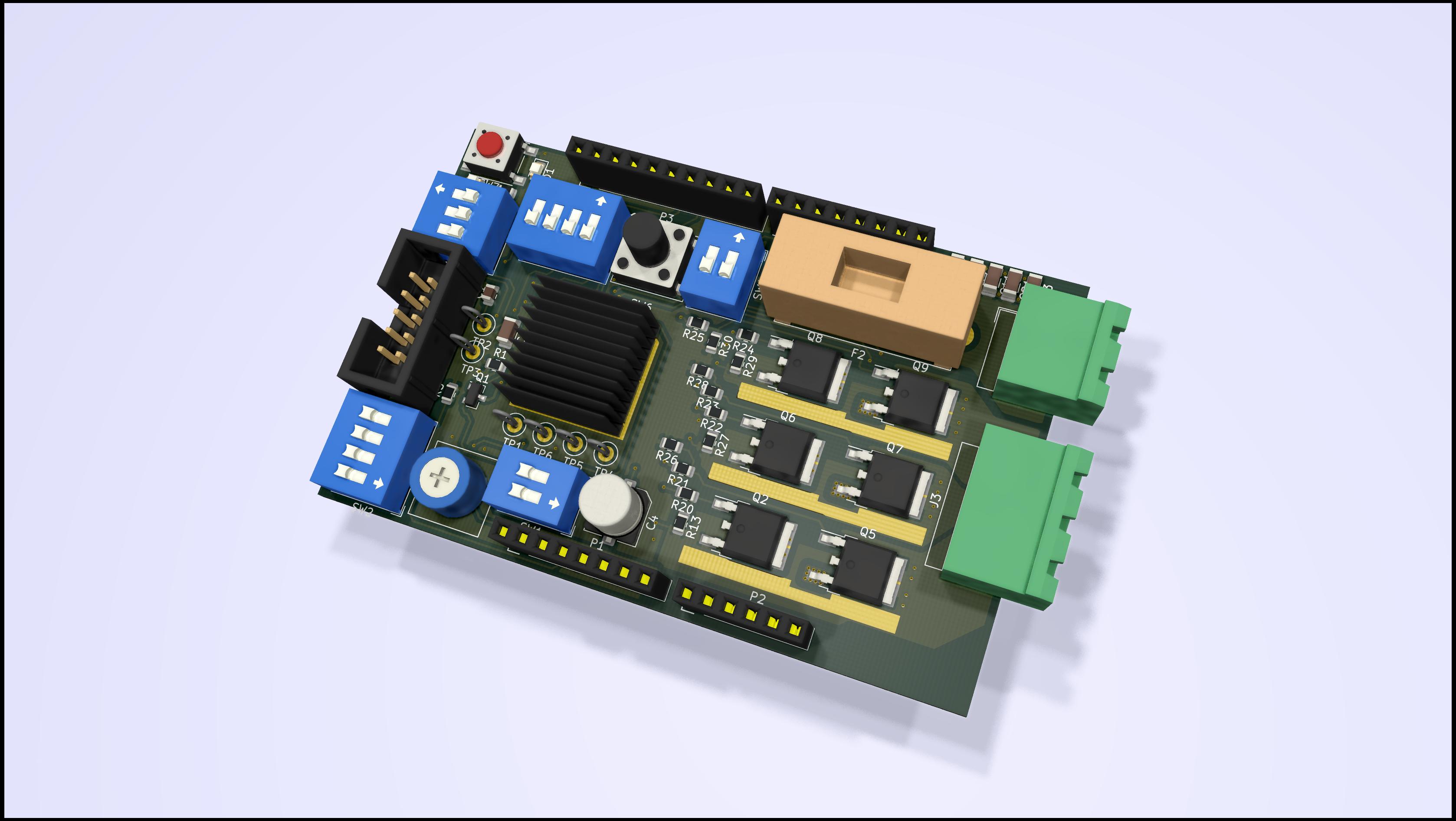
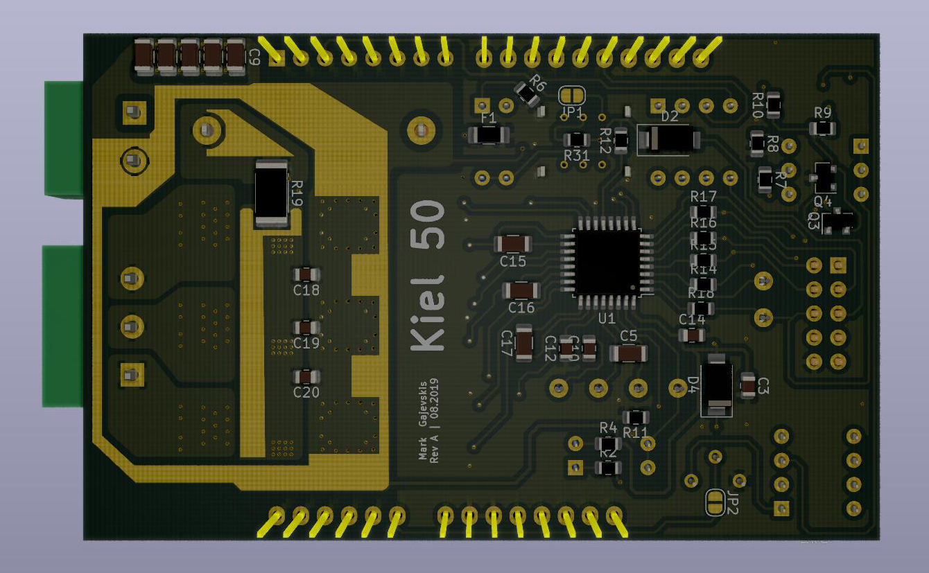
Kiel 50 is an open-source printed circuit board by markgajevskis, from the markgajevskis/Kiel_50 repository on GitHub, published under the GPL-3.0 licence. It is a 2-layer board of 83.8 × 53.3 mm with 94 parts on 94 nets, routed with 744 tracks and 229 vias.
It is built around the RU7570L, BC807 and BC847. Its parts include 31 resistors, 24 capacitors, 9 transistors, 7 connectors and 7 switches.


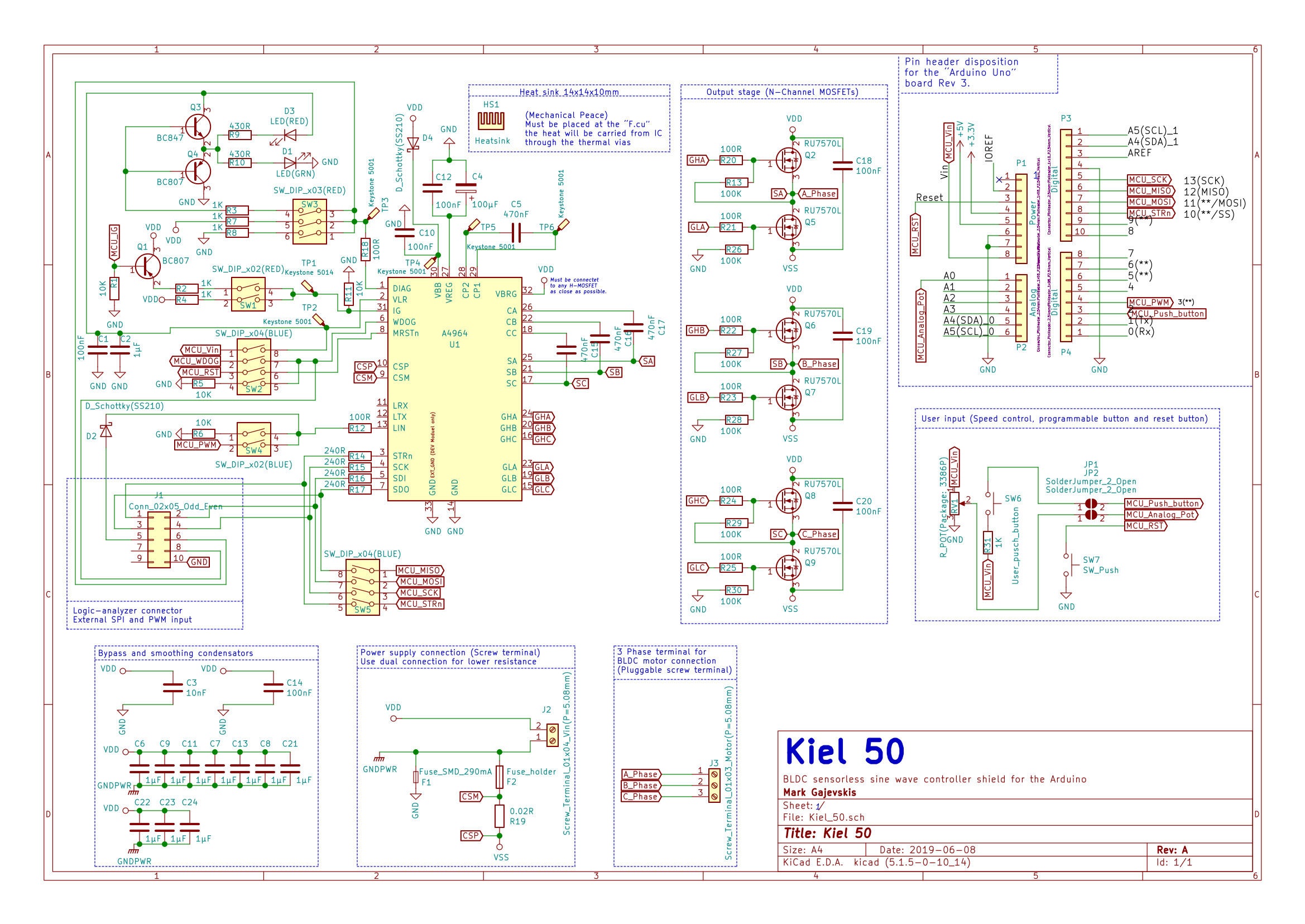
Kiel 50 is an Arduino UNO shield for driving sensor-less three-phase BLDC motor. The main advantage is the sinusoidal current drive. By monitoring the back-EMF (BEMF) the motor can run without the independent rotor position sensor aka hall sensor or encoder. The chip is able to sense the BEMF from very low rpm up to high rpm. The speed can be set and adjusted using PWM or SPI. The Kiel 50 shield comes with the main chip A4964 from "Allegro MicroSystems". This chip is All-in-one: the motor controller, N-Channel MOSFET driver, voltage regulator, MCU watchdog. The ability to program this chip via SPI using Arduino makes it easy to use for many projects. After the configurations were uploaded to the controller and saved to the NVM it can run without Arduino as well.
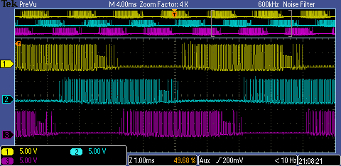
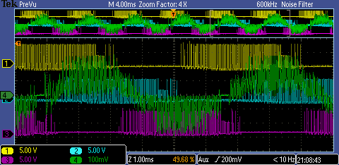
Measurement of the three-phase (Voltage Ch.1,2,3)
Measurment of the three-phase (Voltage Ch.1,2,3 + Current Ch.4 (GN))
| Characteristic | Symbol | Note | Raiting | Unit |
|---|---|---|---|---|
| Supply voltage | Vsup | 5.5 - 50 | V | |
| Logic voltage | VLR | REG 25 - VLR | 3.3 - 5 | V |
| Maximal current | Imax | Fused: F2 | 10 | A |
| Maximal logic current | Ilog | Fused: F1 | 290 | mA |
| Gate drive regulator voltage | Vrg | REG 25 - VRG | 8 or 11 | V |
| Bridge PWM frequency | ƒpw | REG 0 - PW | 14.2 - 50 | Khz |
| PWM frequency (logic) | ƒpwm | 500 - 1000 | Hz | |
| SPI frequency | ƒspi | 2 | Mhz |
| Feature | Description |
|---|---|
| Undervoltage lockout | Controller can detect the voltgae drop and switsch the motor off. Thus avoiding the risk of unpredictible behavior. |
| Peak current limit | Can be programmed using the MCU. Uses shunt for monitoring the current. |
| Ignition switch | The high-active input permitt the system start |
| Bridge MOSFET test | The controller can detect if the driving MOSFETs are broken or have any issues. |
| Windmill detection | If the motor rotetes, the controller can detect its speed and syncronise with it. Thus allowing further rotation without the braiking. |
| MCU watchdog and reset |
| Mode | Description |
|---|---|
| Closed-loop speed | Is used in many e-bike controllers. Acceleration, braking, reaction speed and others settings can be configured via SPI only. After the configuration was set, the speed input via SPI or PWM is acceptable. |
| Closed-loop current | The configuration is done via SPI only. The speed can be adjusted using SPI or PWM. |
| Open-loop speed | The controller ignores the BEMF and keeps switchting the phases based ont the values of the ramp table. |
//ToDo
| Qty | Value | Footprint | References |
|---|---|---|---|
| 11 | 1µF | Capacitor_SMD:C_1206_3216Metric | C2, C7, C8, C9, C11, C13, C21, C22, C23, C24, C25 |
| 8 | 100R | Resistor_SMD:R_0805_2012Metric | R12, R18, R20, R21, R22, R23, R24, R25 |
| 7 | 100nF | Capacitor_SMD:C_0805_2012Metric | C1, C10, C12, C14, C18, C19, C20 |
| 6 | 100K | Resistor_SMD:R_0805_2012Metric | R13, R26, R27, R28, R29, R30 |
| 6 | 1K | Resistor_SMD:R_0805_2012Metric | R2, R3, R4, R7, R8, R31 |
| 6 | RU7570L | Package_TO_SOT_SMD:TO-252-2 | Q2, Q5, Q6, Q7, Q8, Q9 |
| 5 | Keystone 5001 | TestPoint:TestPoint_Loop_D2.50mm_Drill1.0mm | TP2, TP3, TP4, TP5, TP6 |
| 4 | 10K | Resistor_SMD:R_0805_2012Metric | R1, R5, R6, R11 |
| 4 | 240R | Resistor_SMD:R_0805_2012Metric | R14, R15, R16, R17 |
| 4 | 470nF | Capacitor_SMD:C_1206_3216Metric | C5, C15, C16, C17 |
| 2 | 430R | Resistor_SMD:R_0805_2012Metric | R9, R10 |
| 2 | BC807 | Package_TO_SOT_SMD:SOT-23 | Q1, Q4 |
| 2 | D_Schottky(SS210) | Diode_SMD:D_SMA | D2, D4 |
| 2 | SW_DIP_x04(BLUE) | Button_Switch_THT:SW_DIP_SPSTx04_Slide_9.78x12.34mm_W7.62mm_P2.54mm | SW2, SW5 |
| 2 | SolderJumper_2_Open | Jumper:SolderJumper-2_P1.3mm_Open_RoundedPad1.0x1.5mm | JP1, JP2 |
| 1 | 0.02R | Resistor_SMD:R_2512_6332Metric | R19 |
| 1 | 100µF | Capacitor_SMD:C_Elec_6.3x7.7 | C4 |
| 1 | 10nF | Capacitor_SMD:C_0805_2012Metric | C3 |
| 1 | A4964 | Package_QFP:LQFP-32_7x7mm_P0.8mm_with_heat_pad | U1 |
| 1 | Analog | Socket_Arduino_Uno:Socket_Strip_Arduino_1x06 | P2 |
| 1 | BC847 | Package_TO_SOT_SMD:SOT-23 | Q3 |
| 1 | Conn_02x05_Odd_Even | Connector_PinHeader_2.54mm:PinHeader_2x05_P2.54mm_Vertical | J1 |
| 1 | Digital | Connector_PinHeader_2.54mm:PinHeader_1x08_P2.54mm_Vertical | P4 |
| 1 | Digital | Socket_Arduino_Uno:Socket_Strip_Arduino_1x10 | P3 |
| 1 | Fuse_10A | Fuse:Fuseholder_Cylinder-5x20mm_Stelvio-Kontek_PTF78_Horizontal_Open | F2 |
| 1 | Fuse_SMD_290mA | Fuse:Fuse_1206_3216Metric_Pad1.42x1.75mm_HandSolder | F1 |
| 1 | Keystone 5014 | TestPoint:TestPoint_Loop_D2.50mm_Drill1.0mm | TP1 |
| 1 | LED(GRN) | LED_SMD:LED_0805_2012Metric | D1 |
| 1 | LED(RED) | LED_SMD:LED_0805_2012Metric | D3 |
| 1 | Power | Socket_Arduino_Uno:Socket_Strip_Arduino_1x08 | P1 |
| 1 | R_POT(Package: 3386P) | Potentiometer_THT:Potentiometer_Bourns_3386P_Vertical | RV1 |
| 1 | SW_DIP_x02(BLUE) | Button_Switch_THT:SW_DIP_SPSTx02_Slide_9.78x7.26mm_W7.62mm_P2.54mm | SW4 |
| 1 | SW_DIP_x02(RED) | Button_Switch_THT:SW_DIP_SPSTx02_Slide_9.78x7.26mm_W7.62mm_P2.54mm | SW1 |
| 1 | SW_DIP_x03(RED) | Button_Switch_THT:SW_DIP_SPSTx03_Slide_9.78x9.8mm_W7.62mm_P2.54mm | SW3 |
| 1 | SW_Push | Button_Switch_SMD:SW_Push_1P1T_NO_6x6mm_H9.5mm | SW7 |
| 1 | Screw_Terminal_01x03_Motor(P=5.08mm) | TerminalBlock_MetzConnect:TerminalBlock_MetzConnect_Type101_RT01603HBWC_1x03_P5.08mm_Horizontal | J3 |
| 1 | Screw_Terminal_01x04_Vin(P=5.08mm) | TerminalBlock_MetzConnect:TerminalBlock_MetzConnect_Type101_RT01602HBWC_1x02_P5.08mm_Horizontal | J2 |
| 1 | User_pusch_button | Button_Switch_THT:XKB7070-Z-92 | SW6 |
nbolton/esp8266-dual-edge-wake
Open source module for ESP8266, wakes MCU from deep sleep when a sensor value changes

eljotx/SDR-TRX-on-ESP32-A1S
This repository describes an SDR transceiver based on the ESP32 A1S processor, using an ILI9341 color touchscreen display, and a Si5351 oscillator.

Polski-Zwiazek-Krotkofalowcow/qo-100-transverter
Auxiliary unit for the QO-100 transverter, providing:


MR-DOS/TDR_diploma_thesis
Time domain reflectometer. Includes Hardware, firmware and GUI in Octave. Also a diploma thesis.
It measures 83.8 × 53.3 mm and has 2 copper layers, 1.6 mm thick.
94 parts, built around the RU7570L, BC807 and BC847. The full list of its parts is on this page, with links to each part's symbol and footprint where PCBKit's library has them.
From the markgajevskis/Kiel_50 repository on GitHub, at the commit this page was made from: the board is Kiel_50.kicad_pcb. PCBKit opens the board in the browser, with nothing to install.
Its repository publishes it under the GPL-3.0 licence: you may reuse it on that licence's terms (keep the author's notice, and for a copyleft licence share your changes alike).