4 layers99.3 × 92.2 mm
UWU PDB
markantosa/swimbladder
[SUTD SOAR] 8-Thruster Central Star-Node PDB for 8× Blue Robotics T200 + Basic ESC System
67 parts1MIT

 markantosa/swimbladder1
[SUTD SOAR] 8-Thruster Central Star-Node PDB for 8× Blue Robotics T200 + Basic ESC System
UWU PDB is an open-source printed circuit board by markantosa, from the markantosa/swimbladder repository on GitHub, published under the MIT licence. It is a 4-layer board of 96.5 × 92.2 mm with 77 parts on 27 nets, routed with 328 tracks and 170 vias.
Its parts include 19 connectors and 2 diodes. It belongs with the robots and motor control boards of this library.
Power distribution board (PDB) project files for the SwimBladder project.
Silkscreen tag: SOAR UWU | 8 x T200 | V1.1
[!WARNING] This board is an unvalidated, untested work in progress (WIP). It has not completed electrical, thermal, or in-water system validation. Do not treat this design as production-ready hardware.
KiCad Project Files v1.1/ - Canonical KiCad project, PCB, schematic, and the
SwimBladder Custom Footprints library. Open KiCad Project Files v1.1/UWU PDB.kicad_pro.KiCad Project Files/ - Deprecated earlier project set, kept for history. Do not edit.SwimBladder PDB.kicad_sch (repo root) - Stale May snapshot, superseded by the schematic
inside KiCad Project Files v1.1/. Do not use.Screenshots/ - Board and schematic screenshots. v1.1 *.png are current; the unprefixed
files are the earlier V1.0 captures.SwimBladderV1.0.step - 3D board model (V1.0 geometry).Swim_Bladder_Doc_v3_0.pdf - Full engineering reference and calculations. Component values
in this PDF predate the V1.1 schematic changes listed below.This board is designed as a compact 8-thruster central star-node PDB for Blue Robotics T200 systems with 4S battery input. It is currently in a pre-validation state and should be treated as a reference design draft.
J1, J19) feeding one common +VBAT star node, symmetrical wiring for current sharing.C_MAIN1, C_MAIN2 = 4700 uF each.D1 (D_TVS), 22-24 V standoff class for 4S. Recommended part: SMDJ22A
(unidirectional, 3 kW, DO-214AB / SMC footprint, Diode_SMD:D_SMC or D_SMC_HandSolder).R_BLEED1 = 22 kOhm. Draws ~0.76 mA / ~13 mW continuously at full
charge - trivial dissipation for a 0603, well within its power/voltage rating.D2 (LED) with series resistor R_LED1 = 10 kOhm.F_ESC1..F_ESC8 = 30 A.C_ESC1..C_ESC8 = 1000 uF.C_HF1..C_HF8 = 1 uF.J3..J10, XT60 per branch.J2 (Conn_02x08_Odd_Even, 2x8, 2.54 mm), alternating PWM / GND pins.
Suggested part footprint: Connector_IDC:IDC-Header_2x08_P2.54mm_Vertical.J11..J18 (PWM1..PWM8).R_PWM1..R_PWM8 = 100 Ohm.R_PD1..R_PD8 = 10 kOhm.R_PWM*): 0402 hand-solder land pattern
(Resistor_SMD:R_0402_1005Metric_Pad0.72x0.64mm_HandSolder) for IDC header pitch.R_BLEED1, R_LED1, R_PD*) and branch HF caps: 0603
hand-solder (R_0603_1608Metric_Pad0.98x0.95mm_HandSolder /
C_0603_1608Metric_Pad1.08x0.95mm_HandSolder).KiCad Project Files v1.1/SwimBladder Custom Footprints.R_BLEED1 value (now 22 kOhm) have all been resolved.For complete assumptions, formulas, BOM guidance, and test plan, see Swim_Bladder_Doc_v3_0.pdf.
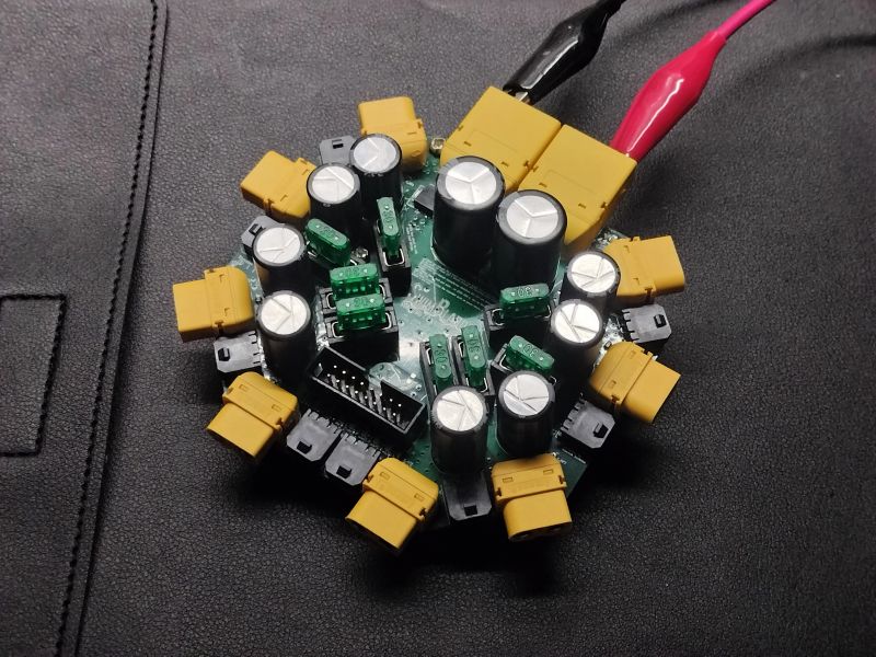
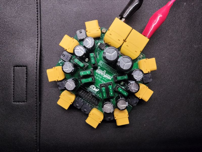
| Assembled Board (1) | Assembled Board (2) |
|---|---|
|  |
| Routing | 3D Render - Top | 3D Render - Isometric |
|---|---|---|
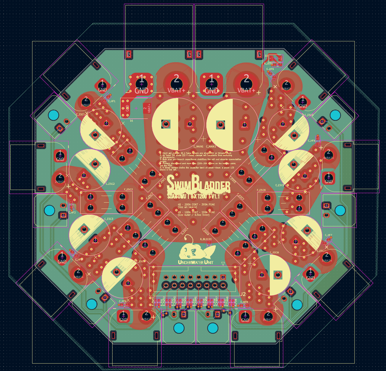 | 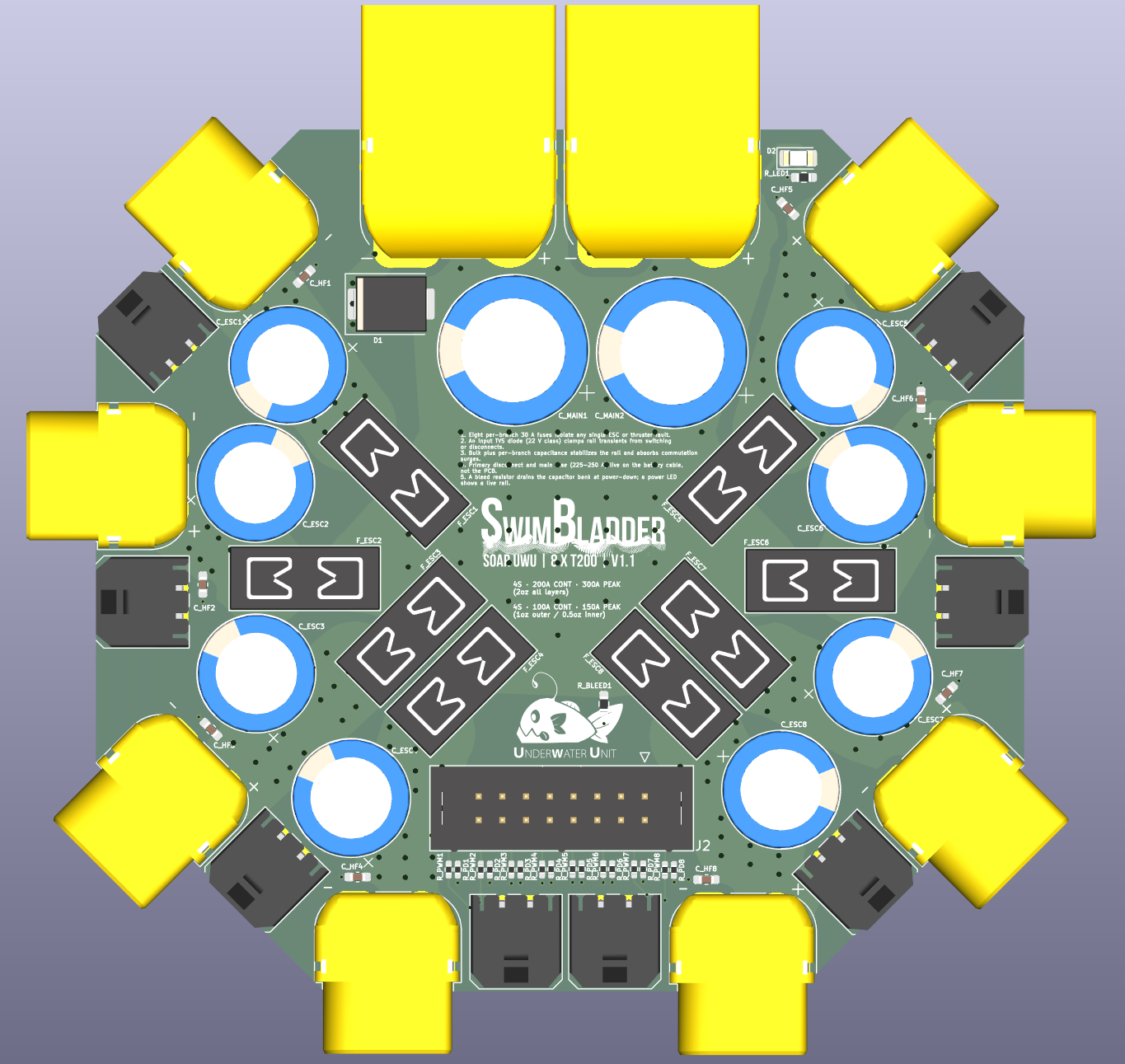 | 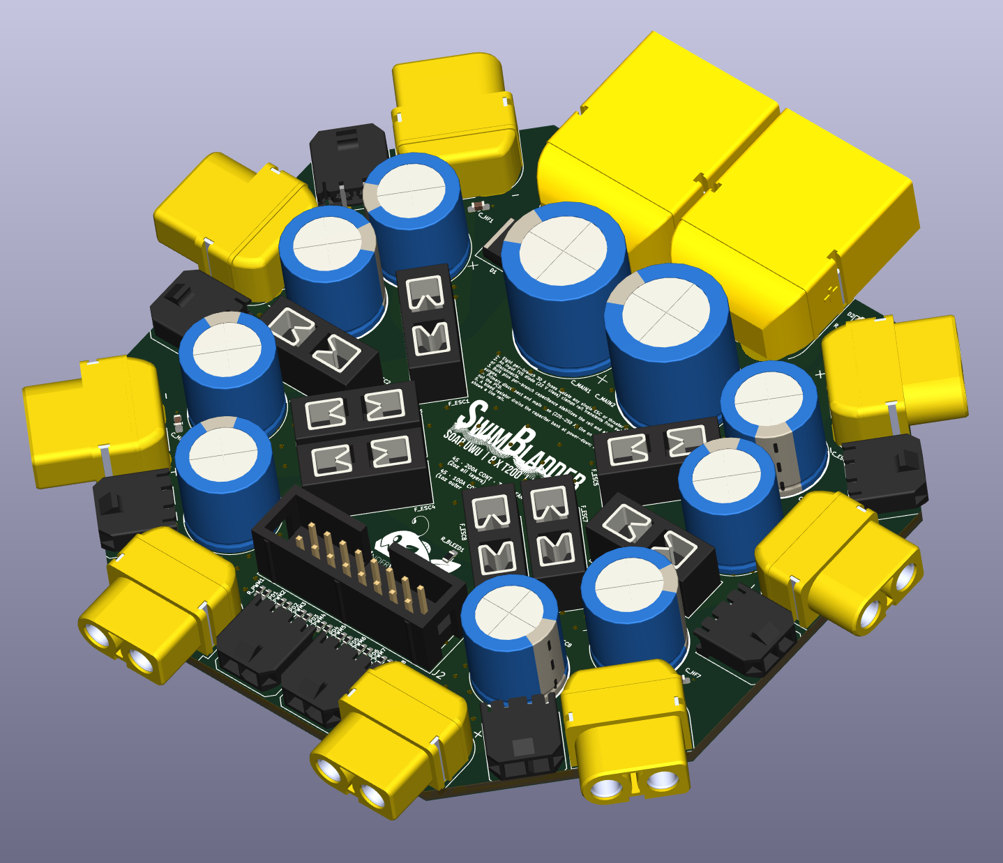 |
Earlier V1.0 captures (Schematic.png, PCB Editor View.png, 3D View.png) remain in Screenshots/ for reference.
KiCad Project Files v1.1/UWU PDB.kicad_pro.KiCad Project Files v1.1/; earlier KiCad Project Files/
and the repo-root SwimBladder PDB.kicad_sch are deprecated.SwimBladder Custom Footprints library.C_MAIN1/2 = 4700 uF each.R_PWM* = 100 Ohm series, R_PD* = 10 kOhm pulldown, inputs J11..J18.R_BLEED1 (value still a placeholder) and status LED D2 / R_LED1.D1 present; placement correction pending (see Known Issues).Bare PCB via JLCPCB; most components via LCSC (SwimBladder_LCSC_BatchBOM_v1.1.csv); full
reference BOM in SwimBladder_BOM_v1.1.csv. JLCPCB and LCSC ship separately even though they're
sister companies - no combined-box option outside of paying for JLC's PCBA assembly service.
R_BLEED1, 22k Ohm, 0603 (LCSC C114065) - MOQ is Min:100/Mult:100, not worth it for ~3
pieces; ask around for spares or buy loose.R_LED1 + R_PD1..R_PD8, 10k Ohm, 0603 (LCSC C98220) - same MOQ issue, ~23 pieces needed.F_ESC1..F_ESC8 - these plug into the Keystone 3568
holder (which is in the LCSC order) but the fuse element itself isn't an LCSC/electronics-
distributor item; source from an automotive parts store or RC supplier.F_ESC1..F_ESC8 fuseholders, Keystone 3568 (x8) - LCSC C5249699 was out of stock, dropped
from the batch order; source from Digi-Key/Mouser instead.D2 status LEDJ2 IDC 2x08 headerR_PWM1..R_PWM8, 100 Ohm, 0402 (from sample book)This project is licensed under the MIT License. See the LICENSE file for details.
| Qty | Value | Footprint | References |
|---|---|---|---|
| 10 | 10k Ohm | Resistor_SMD:R_1206_3216Metric | R_BLEED1, R_LED1, R_PD1, R_PD2, R_PD3, R_PD4, R_PD5, R_PD6, R_PD7, R_PD8 |
| 8 | 1 nF | Capacitor_SMD:C_1206_3216Metric_Pad1.33x1.80mm_HandSolder | C_DEC1, C_DEC2, C_DEC3, C_DEC4, C_DEC5, C_DEC6, C_DEC7, C_DEC8 |
| 8 | 1 uF | Capacitor_SMD:C_1206_3216Metric_Pad1.33x1.80mm_HandSolder | C_HF1, C_HF2, C_HF3, C_HF4, C_HF5, C_HF6, C_HF7, C_HF8 |
| 8 | 100 Ohm | Resistor_SMD:R_1206_3216Metric | R_PWM1, R_PWM2, R_PWM3, R_PWM4, R_PWM5, R_PWM6, R_PWM7, R_PWM8 |
| 8 | 1000 µF | Capacitor_THT:CP_Radial_D12.5mm_P5.00mm | C_ESC1, C_ESC2, C_ESC3, C_ESC4, C_ESC5, C_ESC6, C_ESC7, C_ESC8 |
| 8 | 30 A | Fuse:Fuseholder_Blade_Mini_Keystone_3568 | F_ESC1, F_ESC2, F_ESC3, F_ESC4, F_ESC5, F_ESC6, F_ESC7, F_ESC8 |
| 8 | PWM ESC | Connector_PinHeader_2.54mm:PinHeader_1x03_P2.54mm_Horizontal | J11, J12, J13, J14, J15, J16, J17, J18 |
| 8 | XT60 ESC | Connector_AMASS:AMASS_XT60PW-F_1x02_P7.20mm_Horizontal | J3, J4, J5, J6, J7, J8, J9, J10 |
| 2 | 4700 µF | Capacitor_THT:CP_Radial_D16.0mm_P7.50mm | C_MAIN1, C_MAIN2 |
| 2 | XT90 | Connector_AMASS:AMASS_XT90PW-M_1x02_P10.90mm_Horizontal | J1, J19 |
| 1 | Conn_02x08_Odd_Even | Connector_PinSocket_2.00mm:PinSocket_2x08_P2.00mm_Vertical | J2 |
| 1 | D_TVS | Diode_SMD:D_SMC | D1 |
| 1 | LED | LED_SMD:LED_1206_3216Metric | D2 |
The 73 most common of 77 parts.
markantosa/swimbladder
[SUTD SOAR] 8-Thruster Central Star-Node PDB for 8× Blue Robotics T200 + Basic ESC System


loxodes/vna
Under development open hardware microwave vector network analyzer

OV-Tech-GmbH/OVT13
Open-source thin-and-light 13" laptop

alvarop/debugotron
Debugotron is a collection of debugging/automation tools I've wanted in the past but didn't have access to. Currently, the tools include:

gregdavill/daikin-esp
ESP32-C3 hardware to connect to a Daikin ducted A/C system. enabling WiFi control in Home Assistant.
It measures 96.5 × 92.2 mm and has 4 copper layers, 2.02 mm thick.
77 parts. The full list of its parts is on this page, with links to each part's symbol and footprint where PCBKit's library has them.
From the markantosa/swimbladder repository on GitHub, at the commit this page was made from: the board is KiCad Project Files/UWU PDB.kicad_pcb and its schematic KiCad Project Files v1.1/UWU PDB.kicad_sch. PCBKit opens the board in the browser, with nothing to install.
Its repository publishes it under the MIT licence: you may reuse it on that licence's terms (keep the author's notice, and for a copyleft licence share your changes alike).