2 layers18.5 × 26 mm
24g2usb rp2350zero
joypad-ai/joypad-os
Universal controller firmware for building adapters, dongles, and custom controllers.
4 parts1.7kApache-2.0

 markantosa/orthomate
[SUTD 30.001+30.002+30.100] Adaptive orthopedic insole with FSR pressure sensing, ESP32-C6 control, BLE telemetry via custom Kotlin app, and micro linear stepper actuation for plantar pressure redistribution.
Insole is an open-source printed circuit board by markantosa, from the markantosa/orthomate repository on GitHub, published under the MIT licence. It is a 2-layer board of 32.8 × 23.5 mm with 4 parts on 19 nets, routed with 56 tracks and 0 vias.
It belongs with the robots and motor control and radio and wireless boards of this library.
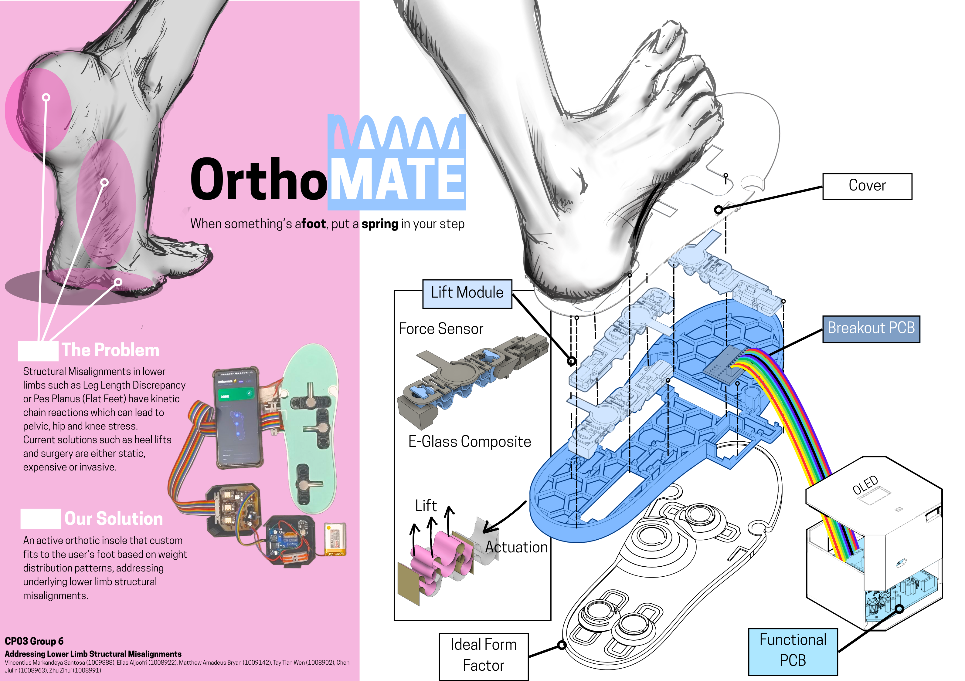
Battery-powered adaptive orthopedic insole controller. Redistributes plantar pressure in real-time using three micro linear stepper actuators driven by force sensor feedback. Includes a BLE companion Android app for live monitoring.
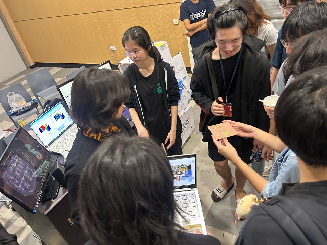
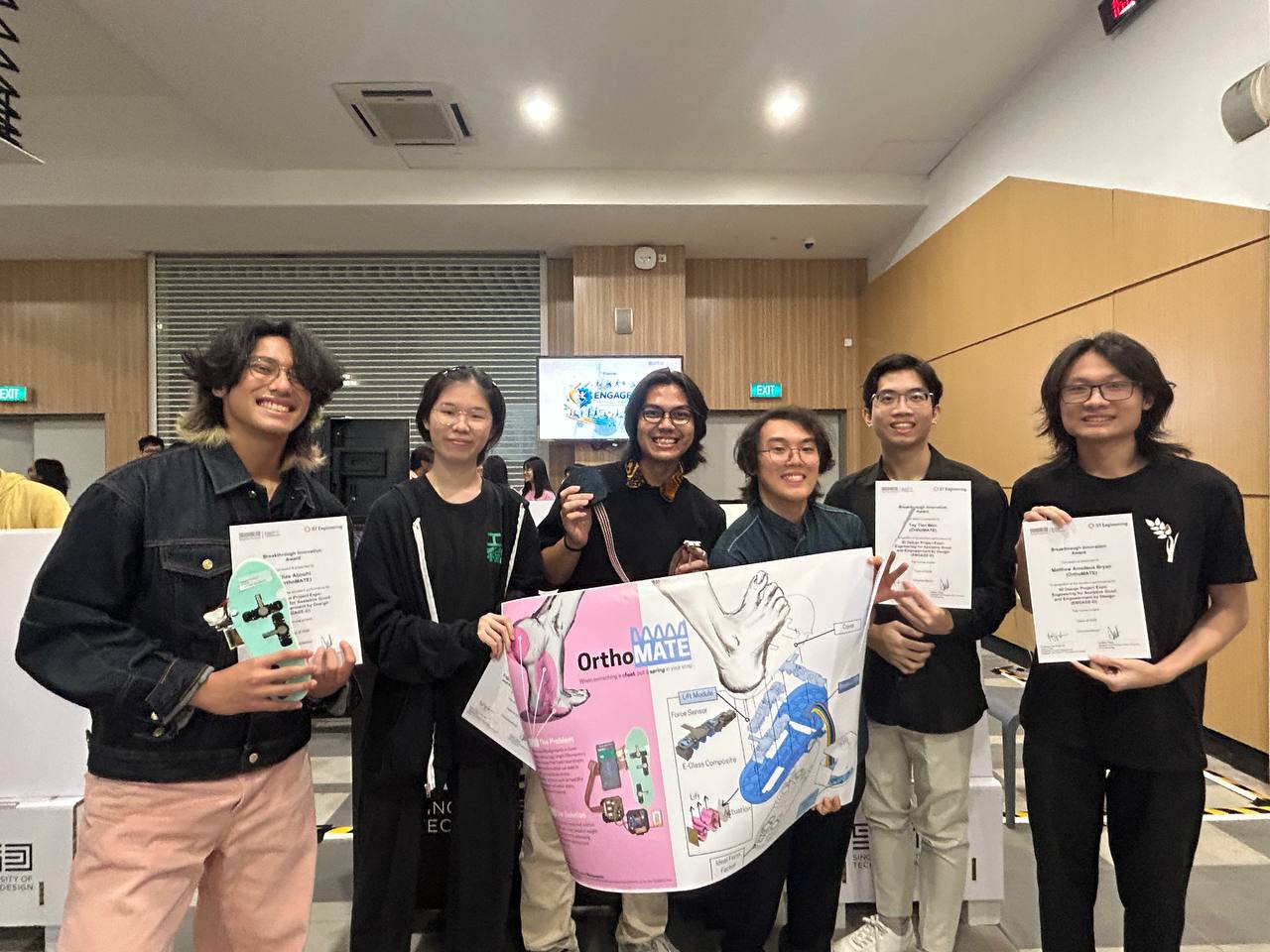
🏆 Winner — Top Course Project, EPD 3D Exhibition April 2026
| Component | Detail |
|---|---|
| MCU | ESP32-C6 SuperMini |
| Stepper drivers | 3× TMC2209 (STEP/DIR mode, ENN hardwired LOW on PCB) |
| Actuators | 3× micro linear bipolar stepper |
| Pressure sensors | 4× FSR (R1 1kΩ + C 100nF RC filter per channel, R2 10kΩ pull-down) |
| Display | 0.91" OLED (SSD1306, I2C) |
| Charger | TP4056 Type-C |
| Boost converter | XL6009 → 5 V system rail |
| Battery | 1S LiPo 2000–3000 mAh |
| User input | 1× momentary mode button |
| BLE | NimBLE-Arduino 2.5.0 — advertises as EPD3DG6 |
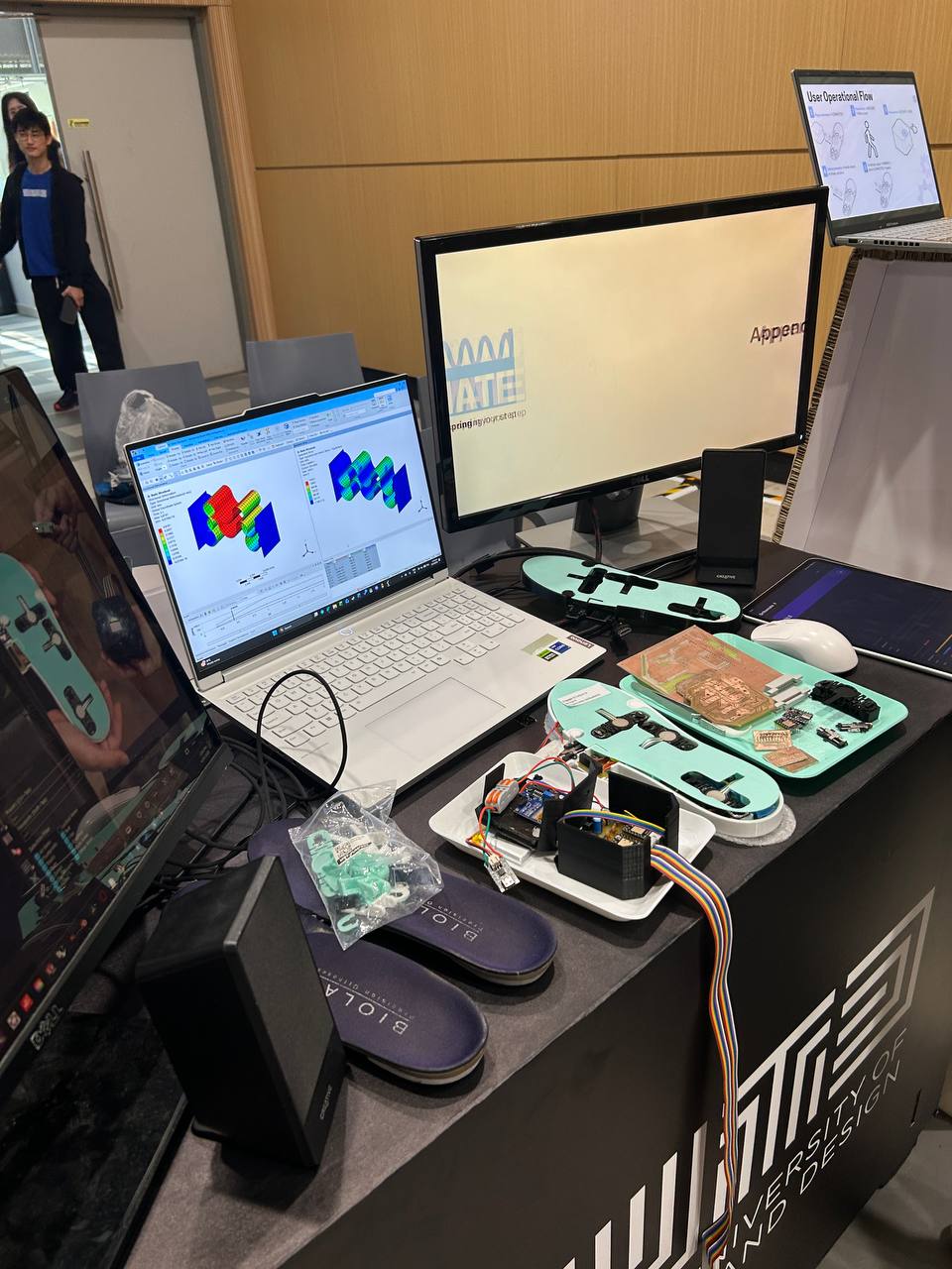
Orthomate uses two custom PCBs that work together inside a modified shoe:
Controller PCB — mounts in a controller module. Houses the ESP32-C6, three TMC2209 stepper drivers, TP4056 charger, XL6009 boost converter, and the 20-pin connector (J9) to the insole. The LiPo battery sits alongside it.
Insole PCB — sits directly underfoot inside the shoe. Hosts the three FSR pressure-sensing zones (metatarsal, arch, calcaneus) and the three micro linear stepper actuator assemblies. The actuators extend upward to redistribute localised plantar pressure. Connects back to the controller PCB via a 20-pin ribbon/wire harness.
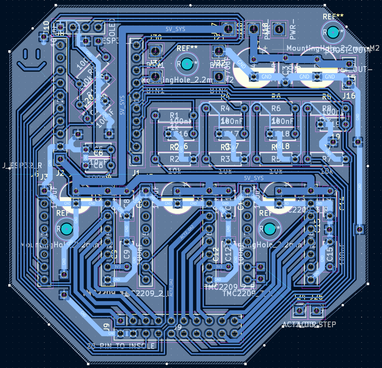
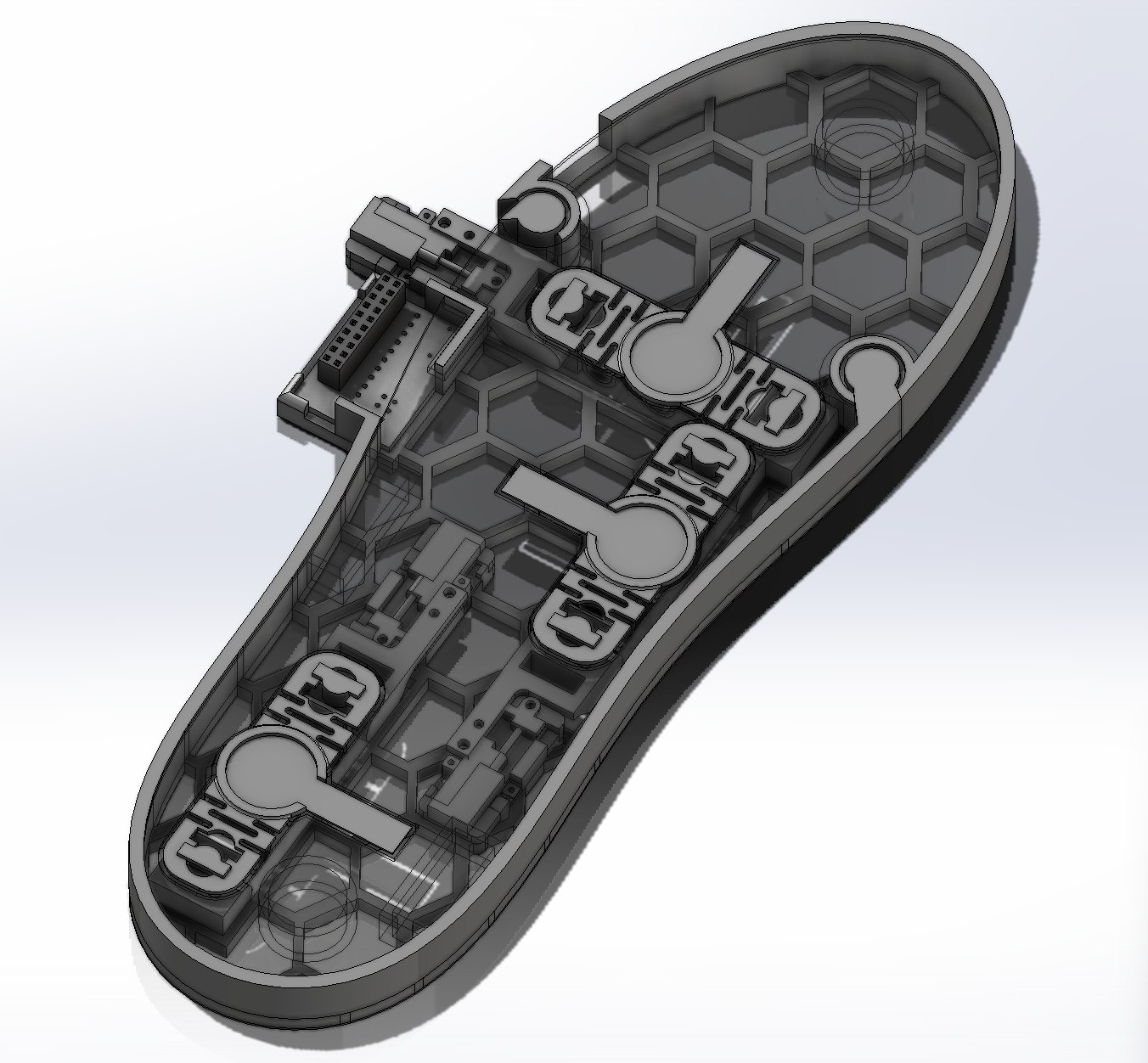
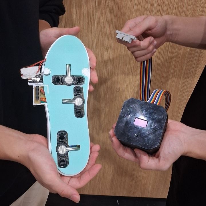
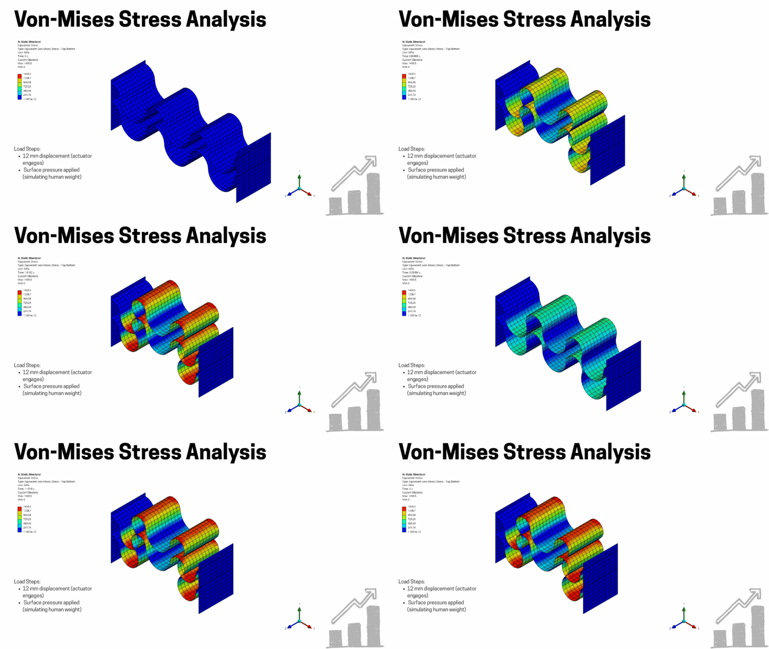
orthomate/
├── Electronics Reference.txt           # Hardware design spec (v6.0)
├── BOM.txt                             # Bill of materials
├── firmware/
│   ├── main/                           # Full operational firmware (PlatformIO)
│   │   ├── platformio.ini
│   │   └── src/main.cpp
│   ├── ARDUINO IDE MAIN/               # Arduino IDE version of the full firmware
│   │   └── EPD3DG6_Main/EPD3DG6_Main.ino
│   ├── ARDUINO IDE APP TEST/           # Minimal Arduino IDE sketch for BLE app testing
│   │   └── sketch_apr14a/sketch_apr14a.ino
│   ├── stepper_test/                   # Single-axis stepper back-and-forth smoke test
│   ├── homing_test/                    # Blind homing: retract to min, extend to 12 mm
│   ├── button_test/                    # Button + OLED input test
│   └── oled_test/                      # OLED display test
├── android_app/                        # Kotlin/Compose BLE companion app
│   └── app/src/main/AndroidManifest.xml
├── Controller PCB KiCad Files/         # KiCad schematic + layout for controller PCB
├── Controller PCB Iterations/          # Gerber files from each revision (V2–V5)
├── Insole PCB KiCad Files/             # KiCad schematic + layout for insole PCB
├── Insole PCB Iterations/              # Gerber files from each revision
├── Exhibition Files and Photos/        # Exhibition media, poster, and slides
└── docs/
├── FIRMWARE_MAIN.md # Detailed firmware walkthroughThe main firmware (firmware/main/) implements a full fitting cycle driven by one button:
DISCONNECTED ──[plug in]──► CONNECTED ──[btn]──► MEASURING
                                                      │ (auto)
                                                  MEASURED ──[btn]──► ACTUATING
                                                                           │ (auto)
                                                                         DONE ──[unplug]──► DISCONNECTED
                                                                         (insole retains shape)

On next plug-in with actuators extended: DISCONNECTED ──► HOMING ──► CONNECTED| Mode | Behaviour |
|---|---|
| CONNECTED | Idle; shows battery %, BLE status on OLED |
| MEASURING | Reads all 4 FSR channels, 7-sample median filter, computes relative load fractions |
| ACTUATING | Drives each actuator inversely proportional to region load — lowest load = largest extension |
| DONE | Holds position; unplug to use insole as-is |
| HOMING | Auto-triggered on reconnect when actuators are extended; retracts all to home |
Extension formula: $ext_i \propto (1 - r_i)$ where $r_i = F_i / \sum F$
The ESP32 advertises a GATT service and notifies a JSON payload at ~4 Hz:
{"fsr1": 42, "fsr2": 18, "fsr3": 75, "mode": "MEASURING", "batt": 67}| BLE field | Value |
|---|---|
| Device name | EPD3DG6 |
| Service UUID | 4fa0c560-78a3-11ee-b962-0242ac120002 |
| Characteristic UUID | 4fa0c561-78a3-11ee-b962-0242ac120002 (NOTIFY + READ) |
| Notify rate | ~4 Hz (every 250 ms) |
| MTU | 185 bytes |
The Android app (android_app/) displays real-time FSR forces as animated colour circles, current mode, battery %, and BLE status. See docs/ANDROID_APP_GUIDE.md for build and install instructions.
| GPIO | Function |
|---|---|
| 0 | FSR1 METATARSAL (ADC, 11 dB attenuation) |
| 1 | FSR2 ARCH (ADC, 11 dB attenuation) |
| 2 | FSR3 CALCANEUS (ADC, 11 dB attenuation) |
| 3 | FSR4 AUX (ADC, 11 dB attenuation) |
| 4 | MODE_BUTTON (INPUT_PULLUP) — boot-safe |
| 5 | VBAT_SENSE (ADC1 ch5, 11 dB attenuation, 1:2 divider) |
| 6 | OLED SCL (I2C) |
| 7 | OLED SDA (I2C) |
| 14 | ACT3_DIR ⚠ dead channel (stepper motor pad detached) |
| 15 | CONN_DETECT (INPUT_PULLDOWN) |
| 16 | ACT2_STEP (arch actuator) |
| 17 | ACT2_DIR (arch actuator) |
| 18 | ACT3_STEP ⚠ dead channel (stepper motor pad detached) |
| 19 | ACT1_DIR |
| 20 | ACT1_STEP |
ADC_11db) on all analog pins for correct readings at the operating voltage range.MIT — see LICENSE
| Qty | Value | Footprint | References |
|---|---|---|---|
| 1 | 20 PIN TO INSOLE | Connector_PinSocket_2.54mm:PinSocket_2x10_P2.54mm_Vertical | J9 |
The 1 most common of 4 parts.
joypad-ai/joypad-os
Universal controller firmware for building adapters, dongles, and custom controllers.


hackclub/OnBoard
💡 Join 1,000 teenagers and make your first PCB with a $100 grant!

tardate/LittleArduinoProjects
a collection of "Little Electronic & Arduino Projects", most involving electronics or an Arduino in one way or another!

drandyhaas/KiCadRoutingTools
A set of Python/Rust tools to aid routing in KiCad

osy/XG_Mobile_Station
Open source eGPU dock for ROG Ally and ROG Flow

Luos-io/luos_engine
Open-source and real-time orchestrator for cyber-physical-systems, to easily design, test and deploy embedded applications and digital twins.

NVNTLabs/switch2-SDEX2M2
Micro SD Express to M.2 NVME Adapter for Nintendo Switch 2
It measures 32.8 × 23.5 mm and has 2 copper layers, 1.6 mm thick.
4 parts. The full list of its parts is on this page, with links to each part's symbol and footprint where PCBKit's library has them.
From the markantosa/orthomate repository on GitHub, at the commit this page was made from: the board is Insole PCB KiCad Files/insole/insole.kicad_pcb and its schematic Controller PCB KiCad Files/EPD 3D G6/EPD 3D G6.kicad_sch. PCBKit opens the board in the browser, with nothing to install.
Its repository publishes it under the MIT licence: you may reuse it on that licence's terms (keep the author's notice, and for a copyleft licence share your changes alike).