4 layers96.4 × 48.3 mm
Embo
markantosa/embo
[SUTD 30.007] Embolisation agent characterisation and automated mixing system
98 parts

 markantosa/embo
[SUTD 30.007] Embolisation agent characterisation and automated mixing system
Embo is an open-source printed circuit board by markantosa, from the markantosa/embo repository on GitHub. It is a 4-layer board of 96.4 × 76.1 mm with 132 parts on 96 nets, routed with 847 tracks and 522 vias.
It is built around the ESP32-S3-WROOM-1-N8, LM2596S-5.0 and AMS1117-3.3, with the BAV99, AO4407A and BAT54 among its other parts. Its parts include 14 connectors, 5 ICs, 1 transistor and 1 fuse. It belongs with the ESP32 boards of this library.


SUTD 30.007 Engineering Design Innovation | Team EMBO | Week 13 of 13
EMBO is a closed-loop medical device that automates and quality-controls the preparation of gelatin foam embolic agents for interventional radiology procedures. It is the first device of its kind to measure and control particle size during embolic agent preparation in real time.
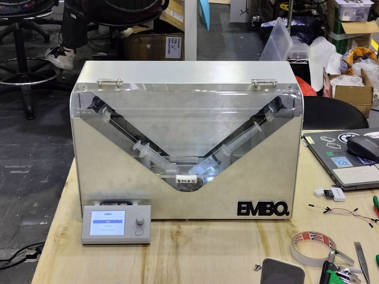 | 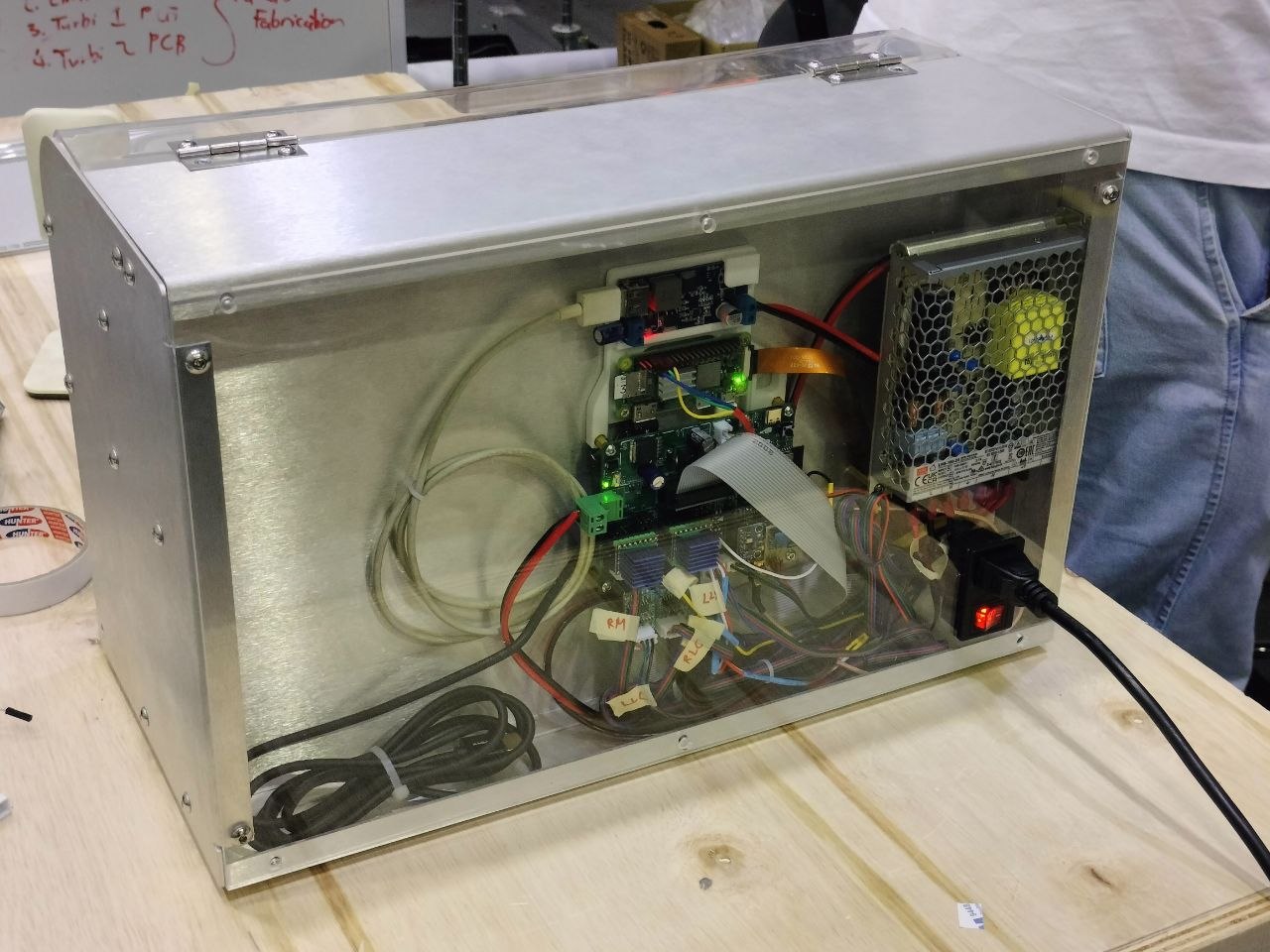 |
| Fully assembled device | Electrical assembly |
CAD renders
| Isometric | Front | Sheet-metal enclosure |
|---|---|---|
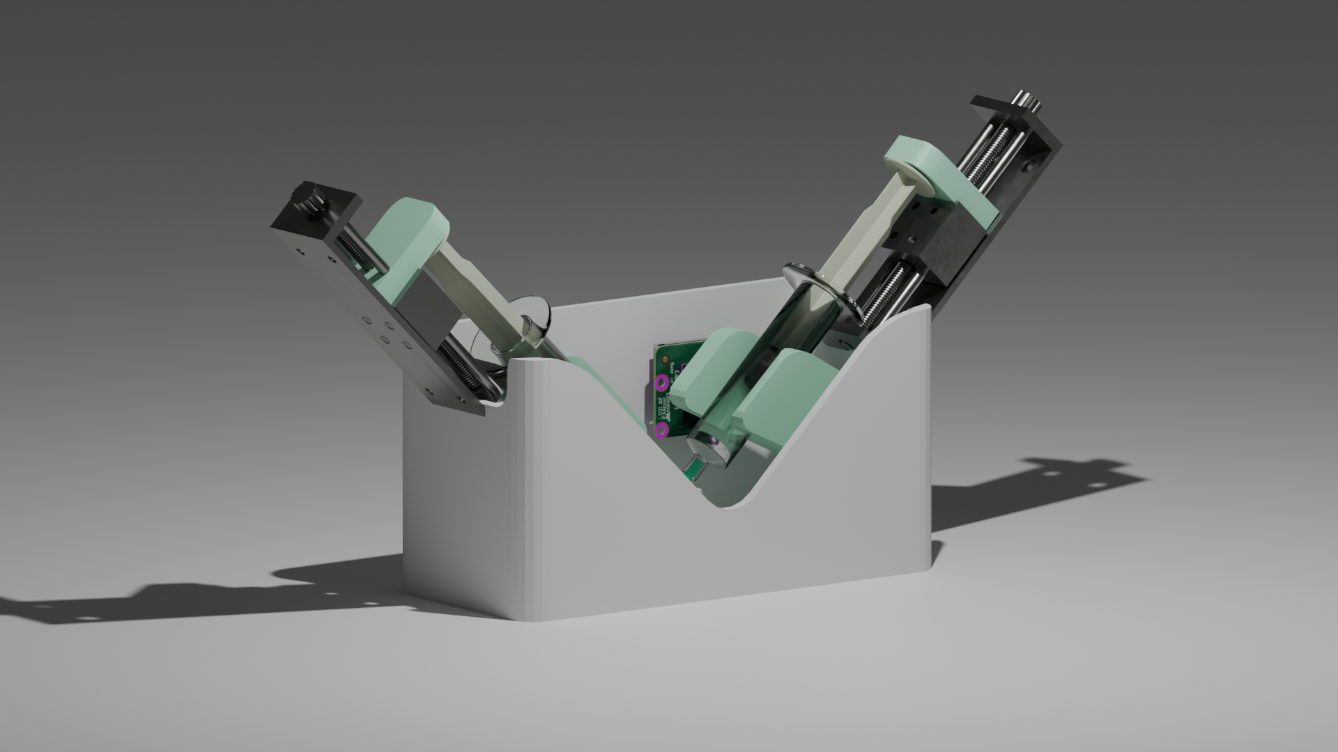 | 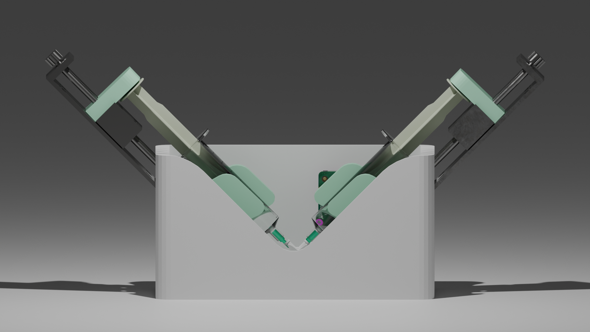 | 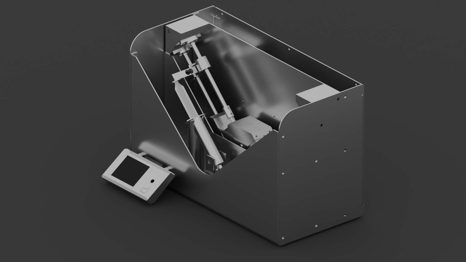 |
| First concept render (Blender) | First concept render (Blender) | CAD (Fusion 360) |
Embolization procedures use tiny gelatin foam particles (embolic agents) to deliberately block blood vessels — treating tumours, fibroids, and bleeding. Before every procedure, a clinician manually prepares a particle slurry by pumping two syringes back and forth until the mixture reaches a "pudding consistency." There is no measurement, no standard, and no quality check. Two clinicians doing this side by side produce slurries with completely different particle size distributions. Particle size directly affects clinical outcomes: wrong sizes can cause tissue death in unintended areas or fail to block the target vessel.
No device currently exists to measure or control particle size during this preparation step. Gelfoam has been used since the 1970s with the preparation method unchanged.
EMBO replaces manual syringe pumping with a controlled, sensor-guided system that:
┌─────────────────────────────────────────────────────────────────┐
│                        EMBO Device                              │
│                                                                 │
│  ┌──────────────────┐          ┌──────────────────────────────┐ │
│  │ Raspberry Pi     │◄─UART──►│     ESP32-S3 MCU Board       │ │
│  │ Zero 2W          │          │                              │ │
│  │  - Roboflow      │          │  - Scheduler control loop    │ │
│  │    hosted CV     │          │    (UAS delta-V closed loop) │ │
│  │    (on-demand)   │          │  - 2× TMC2209 motor drivers  │ │
│  │  - Particle size │          │  - UAS signal chain          │ │
│  │    + annotated   │          │  - ILI9341 TFT UI (LovyanGFX)│ │
│  │    photo         │          │  - BLE debug (NimBLE)        │ │
│  │  - OV9281 CSI    │          │                              │ │
│  │    mono camera   │          │                              │ │
│  └──────────────────┘          └──────────────────────────────┘ │
│           │                             │           │            │
│           ▼                             ▼           ▼            │
│    [Camera + LED]              [Stepper motors] [UAS Transducers]│
│    [Backlight panel]           [Limit switches] [SMA connectors] │
└─────────────────────────────────────────────────────────────────┘Mixing follows first-order breakage kinetics:
D(N) = D_min + (D₀ − D_min) × e^(−kN)Where N is stroke count, k is a shear constant (measured empirically), D₀ is initial particle size, and D_min is the minimum achievable size. The mixing scheduler uses live measurements of D(N) (via the UAS delta-V equation) to decide when to stop.
EMBO/
├── README.md
├── .gitignore
│
├── docs/                              # Design documents and briefs
│   ├── EMBO_Project_Overview.md       # Project context — public/general audience
│   ├── EMBO_PCB_Design_Brief_v3_4.txt # Complete electrical design spec (current)
│   ├── EMBO_PCB_Design_Brief_v3_4.docx / .pdf
│   ├── EMBO_PCB_Design_Brief_v2.51.txt# Superseded — kept for reference
│   └── EMBO_Pinout_Cheatsheet.txt     # Quick GPIO and connector reference (being updated for v3.4)
│
├── hardware/
│   ├── electrical/                    # KiCad schematics + PCB layout — 2 boards:
│   │   │                              #   main board (v3.4, current) + display breakout
│   │   └── README.md
│   └── mechanical/                    # CAD files (SolidWorks / Fusion 360)
│                                      #   Final Pure Assembly.f3z is the current top-level assembly
│       └── README.md
│
├── firmware/
│   └── esp32/                         # ESP32-S3 Arduino/C++ firmware (PlatformIO)
│       ├── README.md                  # Flash guide and peripheral notes
│       └── ../FIRMWARE_TODO.md        # Build-up task list + hardware checklist
│Note: TFT touchscreen UI code lives in firmware/esp32/src/ui.cpp and is tracked in firmware/FIRMWARE_TODO.md — there's no separate software/ui/ folder, since that code only runs on the ESP32, not the Pi.
| Subsystem | Components |
|---|---|
| Microcontroller | ESP32-S3-WROOM-1-N4 (4MB flash, no PSRAM, BLE 5.0, USB-C native programming) — corrected from N8 in v3.3, no pinout impact |
| Motor drivers | 2× MKS TMC2209 V2.0 plug-in modules in 2×8 sockets, field-replaceable; MS1/MS2 jumpers (new v3.4) make both modules interchangeable across UART addresses |
| Ultrasound signal chain | AD9833 DDS → OPA2354 Tx (G=4.9, 2.96Vpp) → transducer → OPA2354 Rx (G=100, interstage AC-coupled) → BAT54 envelope → GPIO1 ADC |
| Turbidity sensing | APDS9960 (I2C 0x39, ALS transmission) + MAX30102 (I2C 0x57, backscatter), shared I2C bus |
| Force sensing | 2× load cell + HX711 amplifier, socketed, shared-clock bit-bang driver — hardware fallback for StallGuard SG_RESULT |
| Display | ILI9341 SPI TFT + XPT2046 resistive touch via 20-pin IDC ribbon to breakout board |
| Power | 24V PSU → F1 (off-board T5A fuse) → F2 (on-board 8A backstop, new v3.4) → AO4407A reverse polarity protection → LM2596 buck (5V) → AMS1117 LDO (3.3V) |
| Comms | UART2 to Raspberry Pi (921600 baud, GPIO47/48); BLE UART debug stream (NimBLE) |
v3.4 is a hardware-hardening pass: 12× 220Ω GPIO protection resistors on every ESP32-to-TMC2209 control line (added after a hot-swap/spark incident on the fabricated v2.51 board), the PDN_UART pin correction (module pin 5, not pin 4), and a full reference-designator naming pass. See hardware/electrical/README.md for the complete changelog.
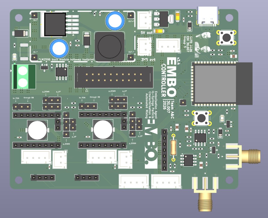 | 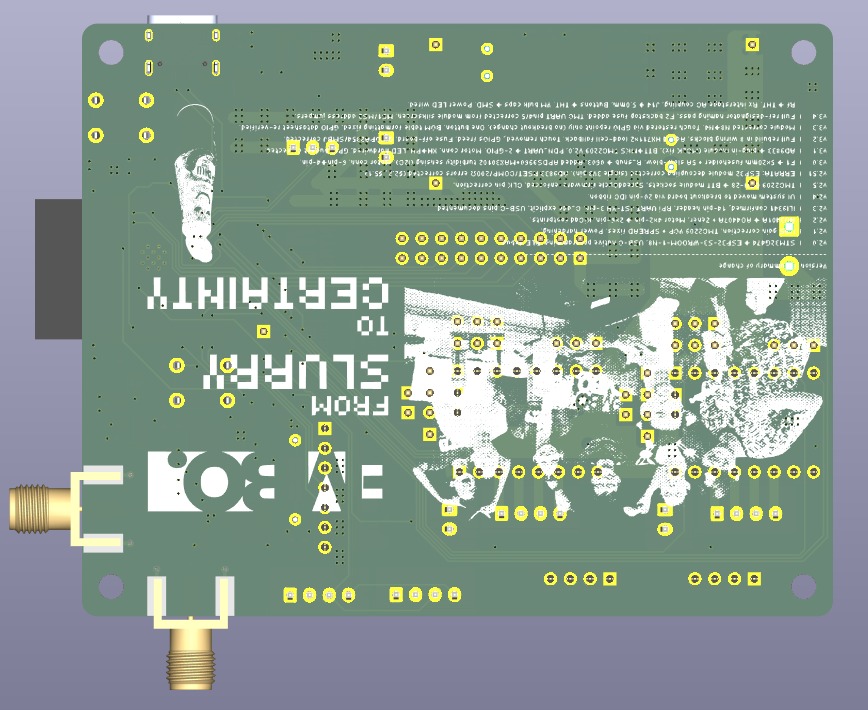 | 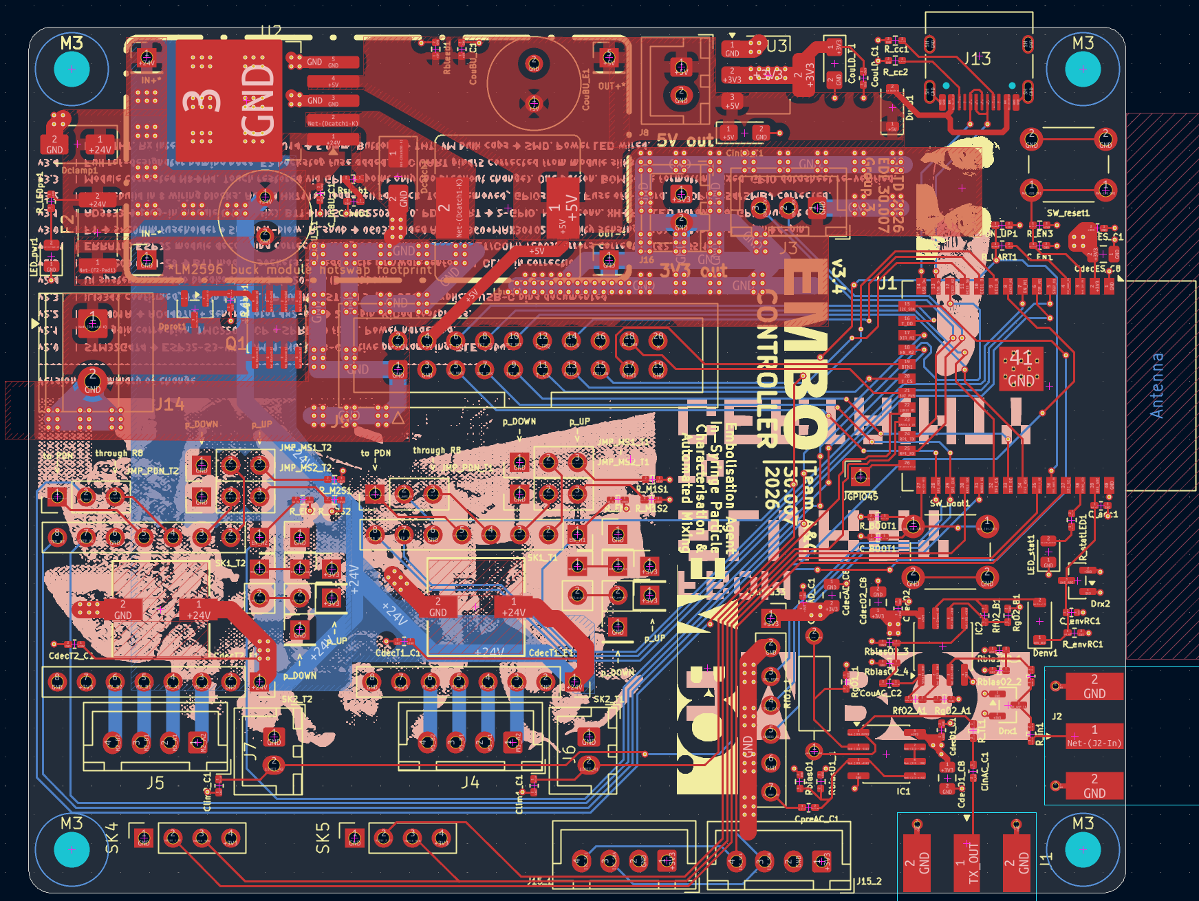 |
| 3D render, front | 3D render, back | KiCad trace routing — L1 + L4 (L2 GND, L3 3V3 hidden for clarity) |
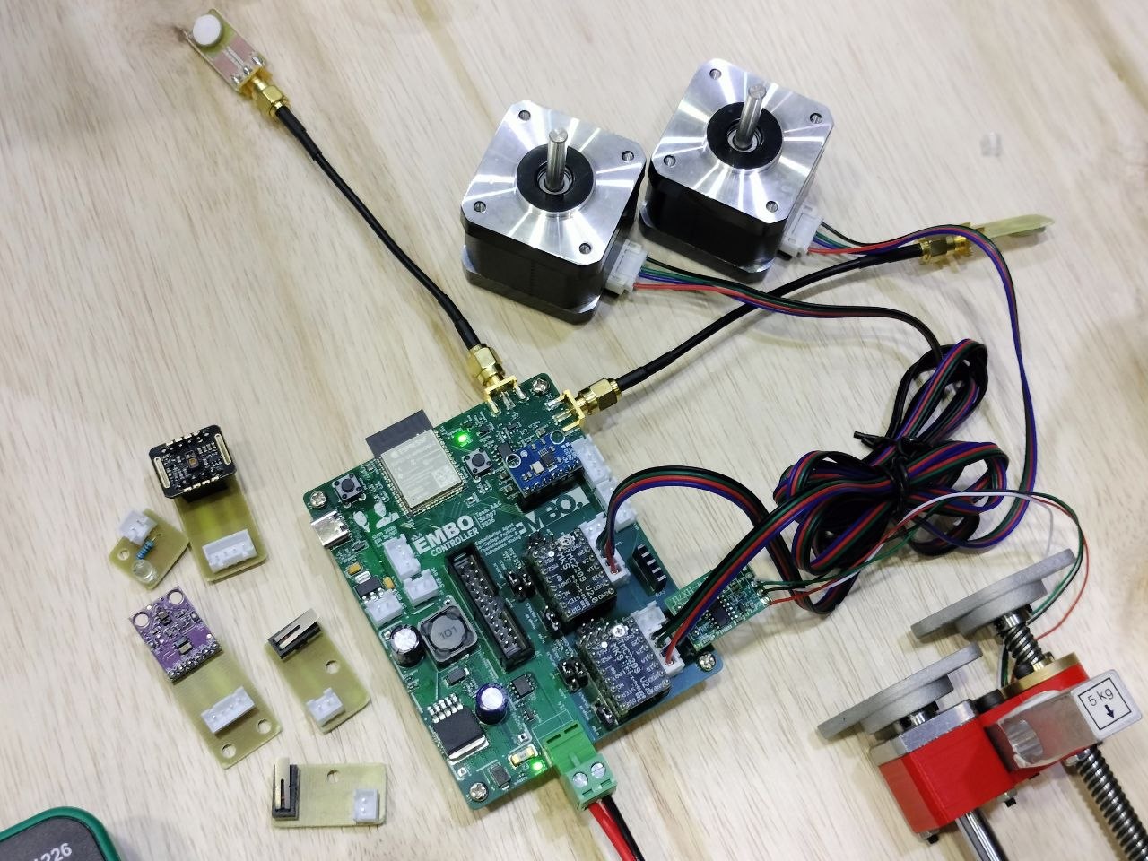 | 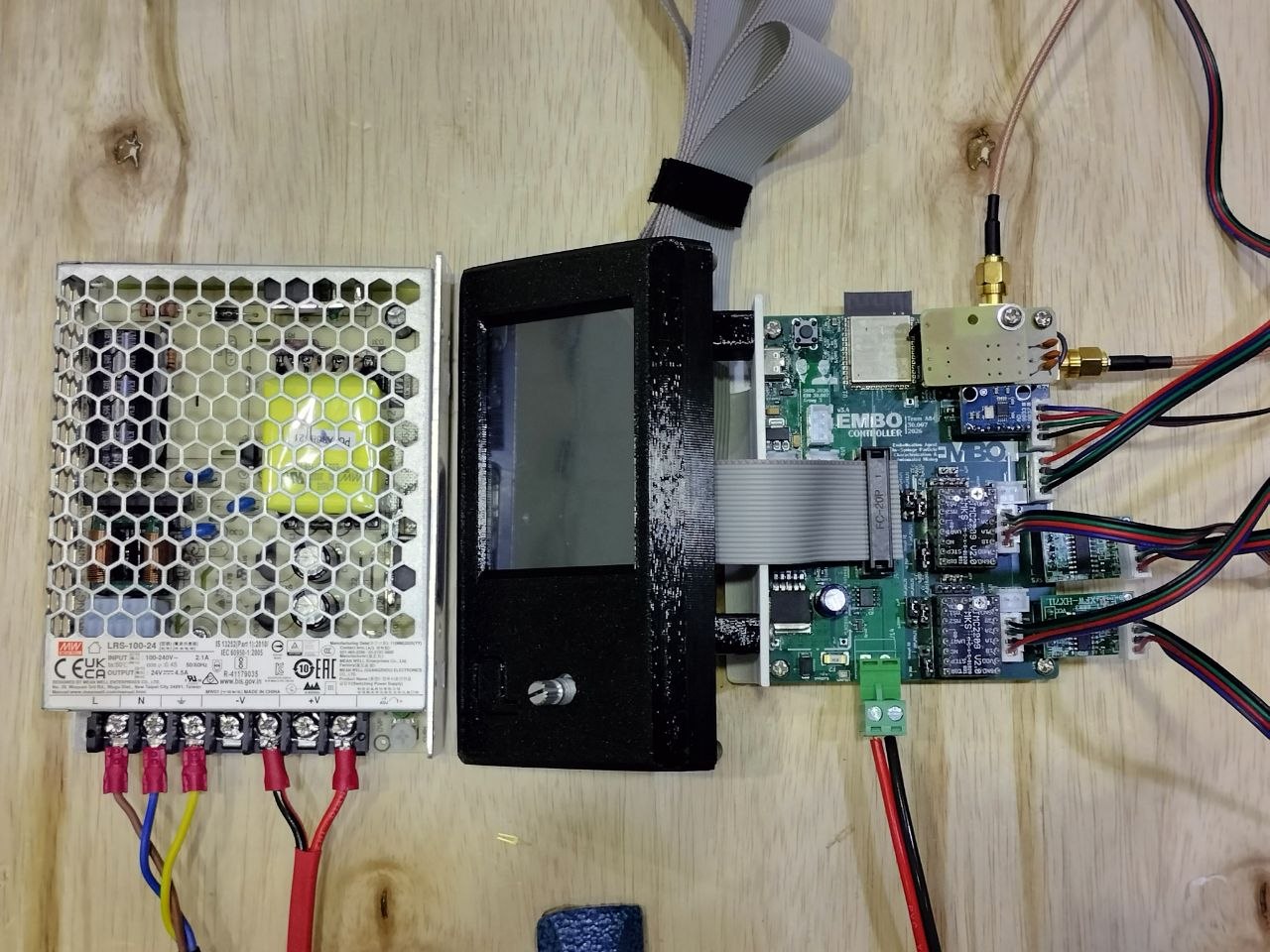 |
| Fabricated board — bring-up | Fabricated board — wired up |
| GPIO | Signal | Notes |
|---|---|---|
| 1 | UAS_ADC | ADC1_CH0 — envelope detector output |
| 3/43 | I2C_SDA/SCL | Shared bus, APDS9960 (0x39) + MAX30102 (0x57), 400kHz |
| 4/44 | TMC_UART TX/RX | Half-duplex, shared PDN bus, via 1kΩ + 220Ω GPIO protection per module |
| 5/8 | STEP_M1/M2 | Hardware timer — step pulse generation, 220Ω GPIO protection |
| 6/9 | DIR_M1/M2 | Motor direction, 220Ω GPIO protection |
| 7/10 | EN_M1/M2 | Motor enable (active LOW, 10kΩ pull-up at IC), 220Ω GPIO protection |
| 14/15 | LIMIT_M1/M2 | Limit switch inputs (internal pull-up) |
| 19/20 | USB D−/D+ | Fixed USB PHY — no UART bridge chip needed |
| 21/37/42 | HX711_2_DT / SCK (shared) / HX711_1_DT | 2× load cell amplifiers, shared clock |
| 35/36 | SPI MOSI/CLK | Shared: AD9833 (Mode 2) + ILI9341 + XPT2046 (Mode 0) |
| 47/48 | RPi TX/RX | UART2 to Raspberry Pi, 921600 baud |
ILI9341 TFT + XPT2046 touch controller on a separate board, connected to the main MCU board via a 20-pin IDC ribbon.
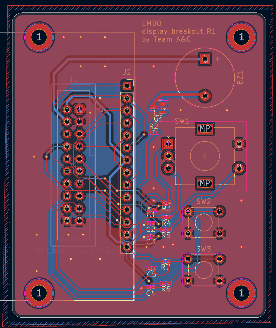 | 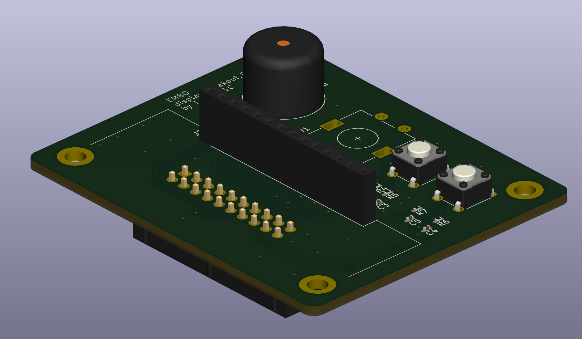 |
| PCB layout | 3D render |
Ultrasound Attenuation Sensing (UAS):
Computer Vision (verification, not closed-loop control):
CAPTURE over UART, the Pi captures + median-stacks frames (noise reduction), runs instance segmentation via a Roboflow-hosted model (RF-DETR, trained on ~100 collected samples), and replies with SIZE <median_um> <iqr_um> plus a downscaled photo with segmentation blob outlines baked in — both rendered on the touchscreen's Camera Verify screen side by side, with an IN SPEC/OUT OF SPEC checksoftware/cv_verify/TODO.md for the full reasoningTurbidity Sensing (added v3.2, hardened v3.4):
firmware/esp32/web/) as Optical Sensor 1/2, alongside every other sensor — see "Getting Started" belowcalibration.cpp) is still unfilled placeholder data for every channel, so only UAS drives the closed loop todayForce Sensing (added v3.2):
| Module | File | Status |
|---|---|---|
| TMC2209 UART, SpreadCycle, StallGuard | src/motors.cpp | ✅ Done |
| LEDC step generation, limit switch ISRs | src/motors.cpp | ✅ Done |
| Homing routine + stroke counter | src/motors.cpp | ✅ Done |
| AD9833 1MHz DDS, UAS ADC calibration | src/uas.cpp | ✅ Done |
| NimBLE wireless debug UART + binary telemetry service | src/ble_debug.cpp, src/ble_binary_telemetry.cpp | ✅ Done |
| RPi UART: SIZE reply parsing + on-demand IMG (annotated photo) receive | src/rpi_uart.cpp | ✅ Done |
| Mixing scheduler: adjustable setpoint (50–1000µm), closed-loop UAS delta-V stop condition | src/scheduler.cpp | ✅ Done — replaces the old PID design |
| TFT UI: encoder-driven menus, live verify screen (photo + PSD/IQR), start/stop-estop | src/ui.cpp, src/ui/screens/ | ⚠️ Touch input still stub (encoder-only works) |
| Turbidity sensors (APDS9960 + MAX30102) | src/turbidity.cpp | ✅ Done — feeds the BLE Telemetry Dashboard; not yet a fusion input (calibration table unfilled) |
See firmware/FIRMWARE_TODO.md for the full task list and hardware bring-up checklist, and firmware/esp32/README.md for the doctor-facing operational workflow (boot → home → set target → run → stop/e-stop).
| Layer | Platform | Language | Key Libraries |
|---|---|---|---|
| Computer vision (on-demand verification) | Raspberry Pi Zero 2W | Python 3 | picamera2, Pillow, NumPy, requests (Roboflow hosted inference — see software/cv_verify/detection.py) |
| Firmware / mixing scheduler | ESP32-S3 | C++ (Arduino) | TMCStepper, NimBLE, LovyanGFX, AD9833 |
| Touchscreen UI | ESP32-S3 | C++ | LovyanGFX |
| BLE debug + telemetry | ESP32-S3 | C++ | NimBLE |
Critical firmware notes:
SPI.beginTransaction().| Sub-team | Responsibilities | Members |
|---|---|---|
| Mechanical | Frame, syringe holders, motor mounts, 3D printed enclosure (FDM + SLA resin), DOE (Design of Experiments) | Alvin, Victoria, Tian Wen |
| Electrical & Software | KiCad schematics + PCB layout (main board + display breakout), component sourcing, board bring-up/testing, ESP32-S3 firmware (mixing scheduler, motor control, UAS), RPi CV verification pipeline (Roboflow), TFT UI | Vincent, Ren Jie, Audrey, Aditi |
| Milestone | Week | Status |
|---|---|---|
| System Requirements Review | 5 | ✅ Complete |
| Recess week — build sprint | 7 | ✅ Complete |
| PCB schematic freeze | End of 7 | ✅ Complete |
| System Design Review | 9 | ✅ Complete |
| Final Exhibition | 13 | ✅ Current |
Requires VS Code + PlatformIO extension. See firmware/esp32/README.md for the full flash guide.
# Quick start
cd firmware/esp32
pio run --target upload   # build and flash
pio device monitor        # serial monitor at 115200
Hold BOOT + press RESET for manual bootloader entry if auto-reset fails.
cd software/cv_verify
python3 -m venv .venv --system-site-packages   # --system-site-packages: sees apt-installed picamera2
source .venv/bin/activate
pip install -r ../requirements.txt
export ROBOFLOW_API_KEY=<your key>             # not stored in any committed file
python3 main.py
See software/cv_verify/SETUP.md for full Pi Zero 2W bring-up (camera/UART dtoverlays, etc.) and software/cv_verify/SESSION_HANDOFF.md for current working state and known issues.
PCB files live in hardware/electrical/ — two boards: the main board (embo main MCU PCB v3_4/, current revision) and the display breakout. Open with KiCad 10. The full design spec including component values, GPIO assignments, layout rules, BOM, and the pre-submission checklist is in docs/EMBO_PCB_Design_Brief_v3_4.txt.
firmware/esp32/web/index_logging to record UAS csv data.html is a Web Bluetooth dashboard for the actual production firmware (not the bench-test project below) — live UAS envelope, both load cells, and both optical/turbidity sensors (labeled Optical Sensor 1/2), plus motor jog/home controls and the automated UAS frequency sweep. Requires BLE to be enabled on-device first (Settings → Developer mode → UAS debug mode), and must be served over http(s) — Web Bluetooth silently fails under a file:// URL:
cd firmware/esp32/web
python3 -m http.server 8000
# open http://localhost:8000/index_logging%20to%20record%20UAS%20csv%20data.htmltesting/PCB_Test_Firmware_v3_4/ is a separate, standalone PlatformIO project for bringing up an assembled v3.4 board pre-final-firmware: reads every sensor (UAS envelope, both load cells, both turbidity channels, both StallGuard results, limit switches), drives the two steppers, and streams it all over BLE to its own Web Bluetooth dashboard (web/index.html) with live strip-charts alongside the raw numbers.
SUTD 30.007 Engineering Design Innovation — Team EMBO — 2026
| Qty | Value | Footprint | References |
|---|---|---|---|
| 19 | 10kΩ 0402 | Resistor_SMD:R_0402_1005Metric_Pad0.72x0.64mm_HandSolder | R_BOOT1, R_EN1, R_EN2, R_EN3, R_envRC1, R_gate1, R_LEDpw1, R_M1S1, R_M1S2, R_M2S1, R_M2S2, R_PDN_UP1, RbiasO1_1, RbiasO1_2, RbiasO2_1, RbiasO2_2 +3 |
| 17 | 100nF X7R | Capacitor_SMD:C_0402_1005Metric_Pad0.74x0.62mm_HandSolder | C_adc1, C_BOOT1, C_inBU_C1, CdecAD_C1, CdecES_C1, CdecO1_C1, CdecO2_C1, CdecT1_C1, CdecT2_C1, CinAC_C1, Clim1_C1, Clim2_C1, CouAC_C1, CouAC_C2, CouBU_C1, CouLD_C1 +1 |
| 9 | Conn_01x01 | Connector_PinHeader_2.54mm:PinHeader_1x01_P2.54mm_Vertical | Jdo_TMC1_extra1, Jdo_TMC1_extra2, Jdo_TMC2_extra1, Jdo_TMC2_extra2, JGPIO45, Jup_TMC1_extra1, Jup_TMC1_extra2, Jup_TMC2_extra1, Jup_TMC2_extra2 |
| 6 | Conn_01x03 | Connector_PinHeader_2.54mm:PinHeader_1x03_P2.54mm_Vertical | JMP_MS1_T1, JMP_MS1_T2, JMP_MS2_T1, JMP_MS2_T2, JMP_PDN_T1, JMP_PDN_T2 |
| 4 | 10µF X5R 0805 | Capacitor_SMD:C_0805_2012Metric | CdecAD_C8, CdecES_C8, CdecO1_C8, CdecO2_C8 |
| 4 | Conn_01x04 | Connector_JST:JST_XH_B4B-XH-A_1x04_P2.50mm_Vertical | J4, J5, J15_1, J15_2 |
| 4 | Conn_01x08 | Connector_PinSocket_2.54mm:PinSocket_1x08_P2.54mm_Vertical | SK1_T1, SK1_T2, SK2_T1, SK2_T2 |
| 4 | MountingHole_3.2mm_M3 | MountingHole:MountingHole_3.2mm_M3 | M3, M3, M3, M3 |
| 3 | 100Ω | Resistor_SMD:R_0402_1005Metric_Pad0.72x0.64mm_HandSolder | RgO1_1, RgO2_A1, RgO2_B1 |
| 2 | 100µF 35V electrolytic radial | Capacitor_SMD:CHEMI-HA0 | CdecT1_E1, CdecT2_E1 |
| 2 | 10µF 10V tantalum Case A | Capacitor_Tantalum_SMD:CP_EIA-3216-18_Kemet-A_HandSolder | CinLD_T1, CouLD_T1 |
| 2 | 5.1kΩ | Resistor_SMD:R_0402_1005Metric_Pad0.72x0.64mm_HandSolder | R_cc1, R_cc2 |
| 2 | 6×6mm tactile | Button_Switch_THT:SW_PUSH_6mm | SW_boot1, SW_reset1 |
| 2 | 910Ω | Resistor_SMD:R_0402_1005Metric_Pad0.72x0.64mm_HandSolder | RfO2_A1, RfO2_B1 |
| 2 | BAV99 | Package_TO_SOT_SMD:SOT-23 | Drx1, Drx2 |
| 2 | Conn_01x02 | Connector_PinSocket_2.54mm:PinSocket_1x02_P2.54mm_Vertical | J_extra_T1_fem1, J_extra_T2_fem1 |
| 2 | Conn_01x02 | Connector_PinHeader_2.54mm:PinHeader_1x02_P2.54mm_Vertical | J_extra_T1_mal1, J_extra_T2_mal1 |
| 2 | Conn_01x04 | Connector_PinSocket_2.54mm:PinSocket_1x04_P2.54mm_Vertical | SK4, SK5 |
| 2 | Conn_Coaxial | Connector_Coaxial:SMA_Molex_73251-1153_EdgeMount_Horizontal | J1, J2 |
| 2 | OPA2354 | Package_SO:SOIC-8_3.9x4.9mm_P1.27mm | IC1, IC2 |
| 1 | 100 µF 50 V radial | Capacitor_THT:C_Radial_D8.0mm_H11.5mm_P3.50mm | C_inBU_E1 |
| 1 | 100µH | Inductor_SMD:L_Bourns_SRR1260 | Lbuck1 |
| 1 | 100Ω 0402 | Resistor_SMD:R_0402_1005Metric_Pad0.72x0.64mm_HandSolder | R_in1 |
| 1 | 10nF X7R | Capacitor_SMD:C_0402_1005Metric | C_envRC1 |
| 1 | 1N5819 | Diode_SMD:D_SOD-123 | Dusb1 |
| 1 | 1kΩ 0402 | Resistor_SMD:R_0402_1005Metric_Pad0.72x0.64mm_HandSolder | R_UART1 |
| 1 | 1nF X7R | Capacitor_SMD:C_0402_1005Metric_Pad0.74x0.62mm_HandSolder | Csnub1 |
| 1 | 1µF X7R | Capacitor_SMD:C_0402_1005Metric_Pad0.74x0.62mm_HandSolder | C_EN1 |
| 1 | 220µF 10V low-ESR electrolytic radial | Capacitor_THT:C_Radial_D8.0mm_H11.5mm_P3.50mm | CouBU_E1 |
| 1 | 24 V PSU input | TerminalBlock_Phoenix:TerminalBlock_Phoenix_MKDS-1,5-2-5.08_1x02_P5.08mm_Horizontal | J14 |
| 1 | 3.3V out | Connector_JST:JST_XH_B2B-XH-A_1x02_P2.50mm_Vertical | J16 |
| 1 | 330Ω | Resistor_SMD:R_0402_1005Metric_Pad0.72x0.64mm_HandSolder | R_statLED1 |
| 1 | 390Ω | Resistor_THT:R_Axial_DIN0207_L6.3mm_D2.5mm_P10.16mm_Horizontal | RfO1_1 |
| 1 | 4.7kΩ | Resistor_SMD:R_0402_1005Metric_Pad0.72x0.64mm_HandSolder | Rbleed1 |
| 1 | 47Ω | Resistor_SMD:R_0402_1005Metric_Pad0.72x0.64mm_HandSolder | R_TL1 |
| 1 | 5A littlefuse | Fuse:Fuse_2512_6332Metric | F2 |
| 1 | 5V out | Connector_JST:JST_XH_B2B-XH-A_1x02_P2.50mm_Vertical | J8 |
| 1 | AMS1117-3.3 | Package_TO_SOT_SMD:SOT-223-3_TabPin2 | U3 |
| 1 | AO4407A | Package_SO:SOIC-8_3.9x4.9mm_P1.27mm | Q1 |
| 1 | BAT54 | Diode_SMD:D_SOD-123 | Denv1 |
| 1 | BZX84C15, 15 V Zener, SOT-23 | Package_TO_SOT_SMD:SOT-23 | Dprot1 |
| 1 | Conn_01x03 | Connector_JST:JST_XH_B3B-XH-A_1x03_P2.50mm_Vertical | J3 |
| 1 | Conn_01x07 | Connector_PinSocket_2.54mm:PinSocket_1x07_P2.54mm_Vertical | J_AD9833 |
| 1 | Conn_02x10_Odd_Even | Connector_IDC:IDC-Header_2x10_P2.54mm_Vertical | J9 |
| 1 | ESP32-S3-WROOM-1 | RF_Module:ESP32-S3-WROOM-1 | U1 |
| 1 | LED_pwr | LED_SMD:LED_0805_2012Metric | LED_pwr1 |
| 1 | LM2596S-5 | Package_TO_SOT_SMD:TO-263-5_TabPin3 | U2 |
| 1 | LOGO | EMBO_Custom_Footprints:EMBO LOGO | G*** |
| 1 | LOGO | EMBO_Custom_Footprints:PROFS2 | G*** |
| 1 | LOGO | EMBO_Custom_Footprints:EMBO7 | G*** |
| 1 | SMBJ28A | Diode_SMD:D_SMA | Dclamp1 |
| 1 | SS34A | Diode_SMD:D_SMA | Dcatch1 |
| 1 | USB_C_Receptacle_USB2.0_16P | Connector_USB:USB_C_Receptacle_HRO_TYPE-C-31-M-12 | J13 |
| 1 | green LED | LED_SMD:LED_0805_2012Metric | LED_stat1 |
| 1 | motor 1 | Connector_JST:JST_XH_B2B-XH-A_1x02_P2.50mm_Vertical | J6 |
| 1 | motor 2 | Connector_JST:JST_XH_B2B-XH-A_1x02_P2.50mm_Vertical | J7 |
The 128 most common of 132 parts.
markantosa/embo
[SUTD 30.007] Embolisation agent characterisation and automated mixing system

markantosa/embo
[SUTD 30.007] Embolisation agent characterisation and automated mixing system

markantosa/embo
[SUTD 30.007] Embolisation agent characterisation and automated mixing system

markantosa/embo
[SUTD 30.007] Embolisation agent characterisation and automated mixing system

markantosa/embo
[SUTD 30.007] Embolisation agent characterisation and automated mixing system

markantosa/embo
[SUTD 30.007] Embolisation agent characterisation and automated mixing system

markantosa/embo
[SUTD 30.007] Embolisation agent characterisation and automated mixing system

markantosa/embo
[SUTD 30.007] Embolisation agent characterisation and automated mixing system

markantosa/embo
[SUTD 30.007] Embolisation agent characterisation and automated mixing system


etiennechlt/electronic-chess
Générée par tools/boardgen (module power). 100 x 60 mm, 2 couches, plan de masse en face arrière. Elle gère trois cellules plates 1S 5 Ah.


beaked99/air-scales
2025-11-20. Updated all the footprints and symbols to their proper layouts. no more fkn errors. Hallefuckinglujah. Fucked up with LM74610 not using the right footprint. minor fix. 2025-11-16.

JosueHerrera05/Josue_Herrera_Electiva_2026_C2
Repositorio Electíva Diseño Mecatrónico 2026-C2

paulmartinezcuenta/PLC4UNI
Development of programmable logic controller, product for mechatronic design.

ashton6student/ece445
Note: each subfolder has its own README.md file that forms the ECE 445 notebook, in addition to this top-level file.
It measures 96.4 × 76.1 mm and has 4 copper layers, 1.6 mm thick.
132 parts, built around the ESP32-S3-WROOM-1-N8, LM2596S-5.0, AMS1117-3.3 and BAV99. The full list of its parts is on this page, with links to each part's symbol and footprint where PCBKit's library has them.
From the markantosa/embo repository on GitHub, at the commit this page was made from: the board is hardware/electrical/embo main MCU PCB v3_4/embo.kicad_pcb and its schematic hardware/electrical/APDS9960 PCB/APDS9960/APDS9960.kicad_sch. PCBKit opens the board in the browser, with nothing to install.
Its repository states no licence, so its author keeps all rights: ask markantosa before reusing the design.