2 layers203 × 26.6 mm

 mariosgit/V2164-TesterAndMixer1
Tester and Stereo Mixer for V2164 SSM2164.
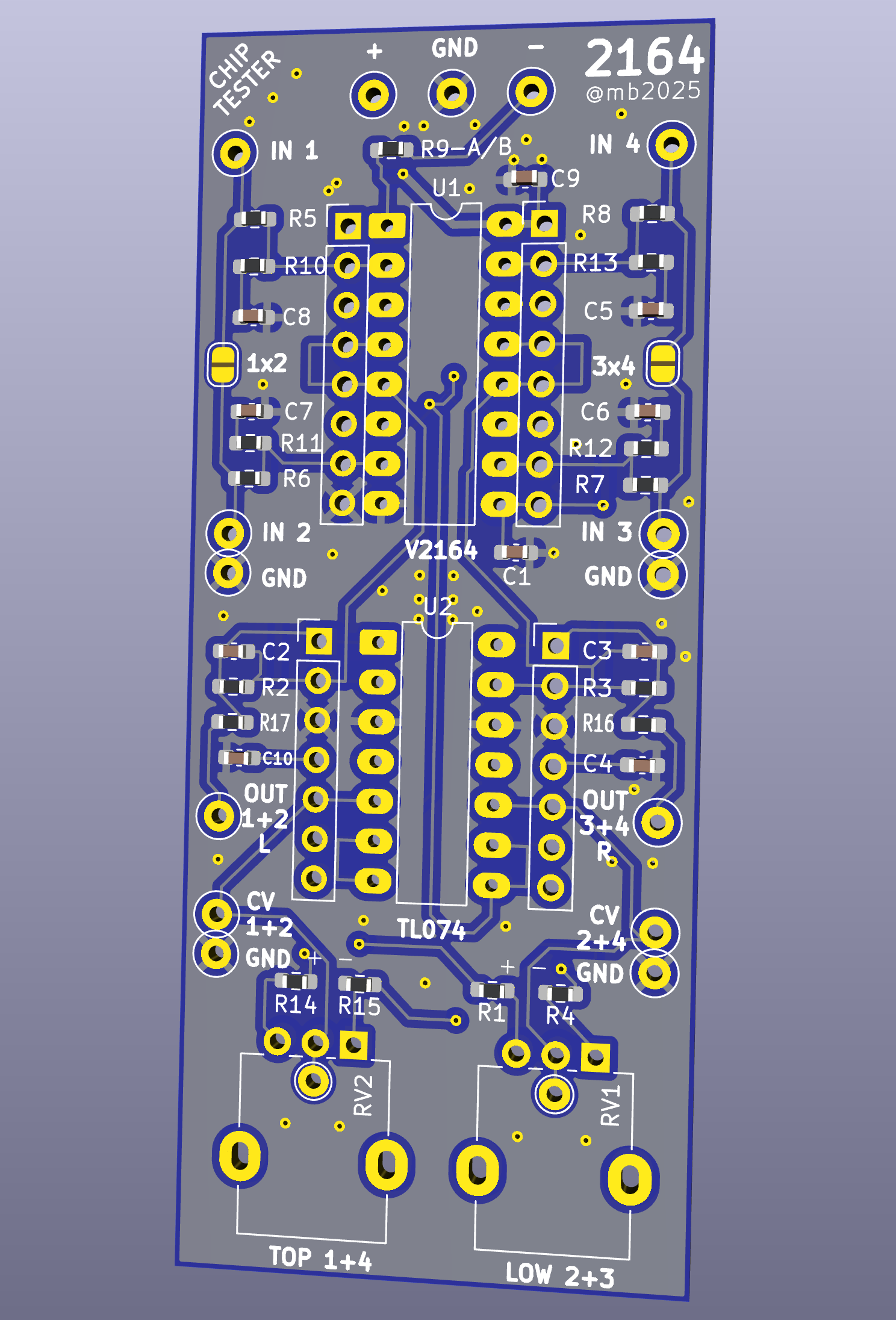
V2164tests is an open-source printed circuit board by mariosgit, from the mariosgit/V2164-TesterAndMixer repository on GitHub, published under the MIT licence. It is a 2-layer board of 33 × 80 mm with 54 parts on 30 nets, routed with 242 tracks and 51 vias.
Its parts include 17 resistors, 10 capacitors, 4 connectors and 2 ICs.
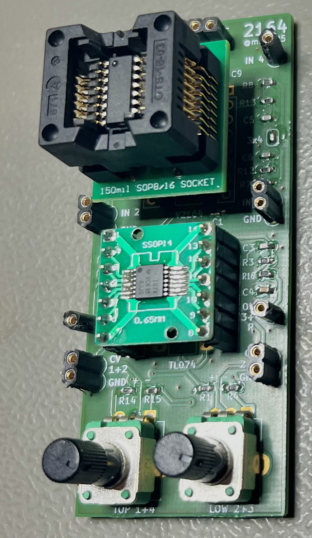
Simple board to test V2164 chips. Follows the application example in the SSM2164 datasheet.
Can also be used as a 2 channel stereo mixer.
 |  |
Ok.
For cleverness sake, chip adapters can be used.
With R1/R4 and R14/R15 the range of the pots can be limited. For testing u can just short these. In theory 0V is 0dB and then the gain factor is -33mV/dB with a max range of -120..+20 dB, that equals 3.96V=-120dB to -0.66V=+20dB.
Ask your favorite chat bot for a voltage divider fitting your needs.
To design a voltage divider with three resistors in series between +12V and -12V that meets your specified voltage requirements, we'll follow these steps:

### Given:
- **Supply voltages**: +12V (top) and -12V (bottom)
- **Middle resistor (R₂)**: 10 kΩ
- **Desired voltage at top of R₂ (V₂)**: +3.96V
- **Desired voltage at bottom of R₂ (V₃)**: -0.66V

bla bla bla...

### Final Resistor Values:
- **Top resistor (R₁)**: **17.4 kΩ**
- **Middle resistor (R₂)**: **10 kΩ** (given)
- **Bottom resistor (R₃)**: **24.55 kΩ**

### Practical Considerations:
- You may need to use standard resistor values close to the calculated ones (e.g., 17.4 kΩ ≈ 17.8 kΩ or 18 kΩ; 24.55 kΩ ≈ 24.9 kΩ or 25 kΩ).
- For higher precision, you can use a potentiometer or combine resistors in series/parallel.
Or use the experimental falstad circuit.
| References | Value | Footprint | Quantity |
|---|---|---|---|
| C5, C6, C7, C8 | 560p | 603 | 4 |
| C2, C3 | 220p (100p+) | 603 | 2 |
| R2, R3, R5, R6, R7, R8 | 33k | 603 | 6 |
| R10, R11, R12, R13, R16, R17 | 470 | 0603 | 6 |
| R1, R4, R14, R15 | 5k see notes | 603 | 4 |
| R9 | 7.5k for class A or open for class AB | 603 | 1 |
| U1 | SSI2164 | DIP-16 7.62mm or SO-16 + Adapter | 1 |
| U2 | TL074 or any such 4x OpAmp | DIP-14 7.62mm or SO/SOP/TSOP-14 + Adapter | 1 |
| RV1, RV2 | 10k see notes | 9mm Potentiometer Vertical | 2 |
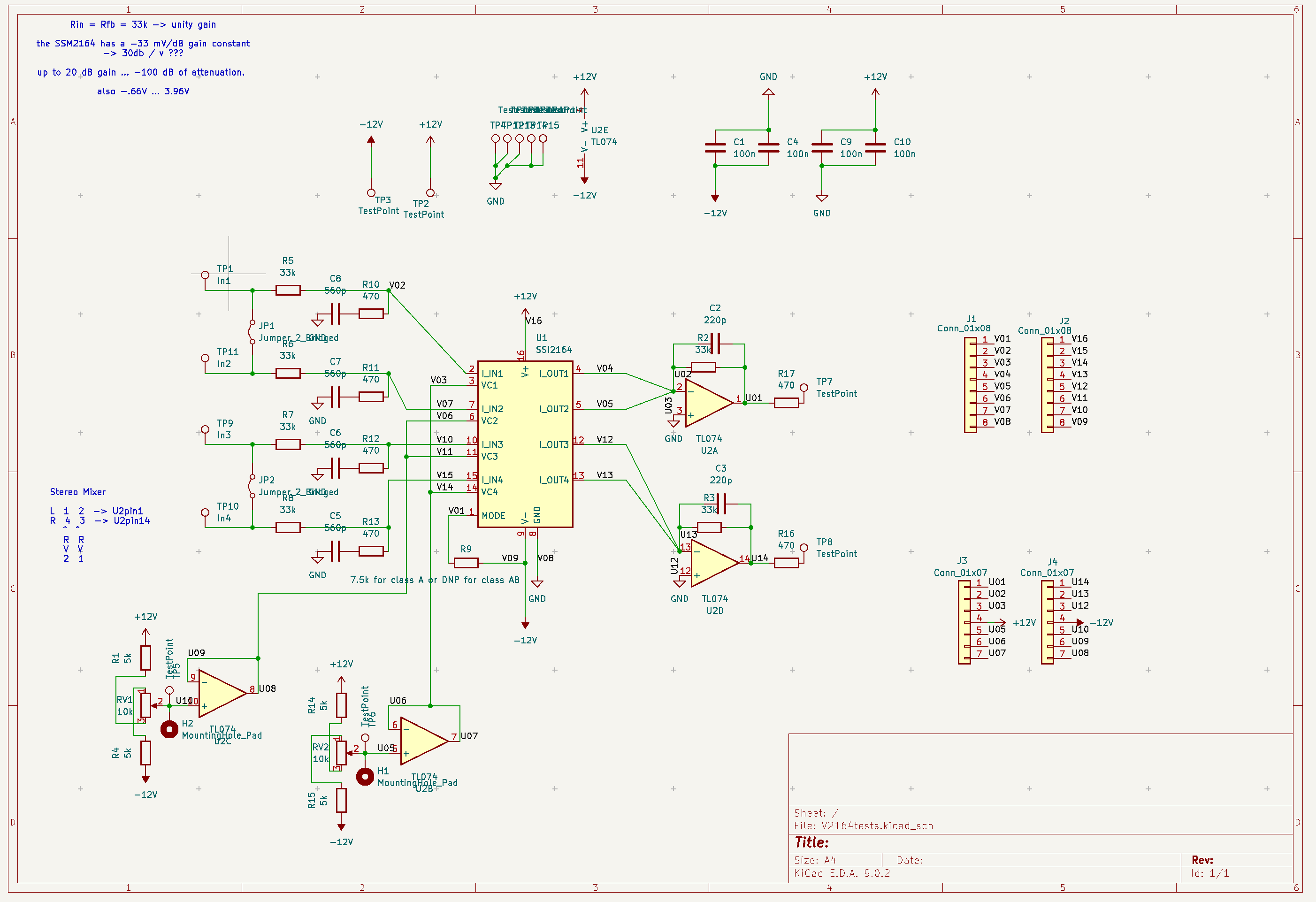
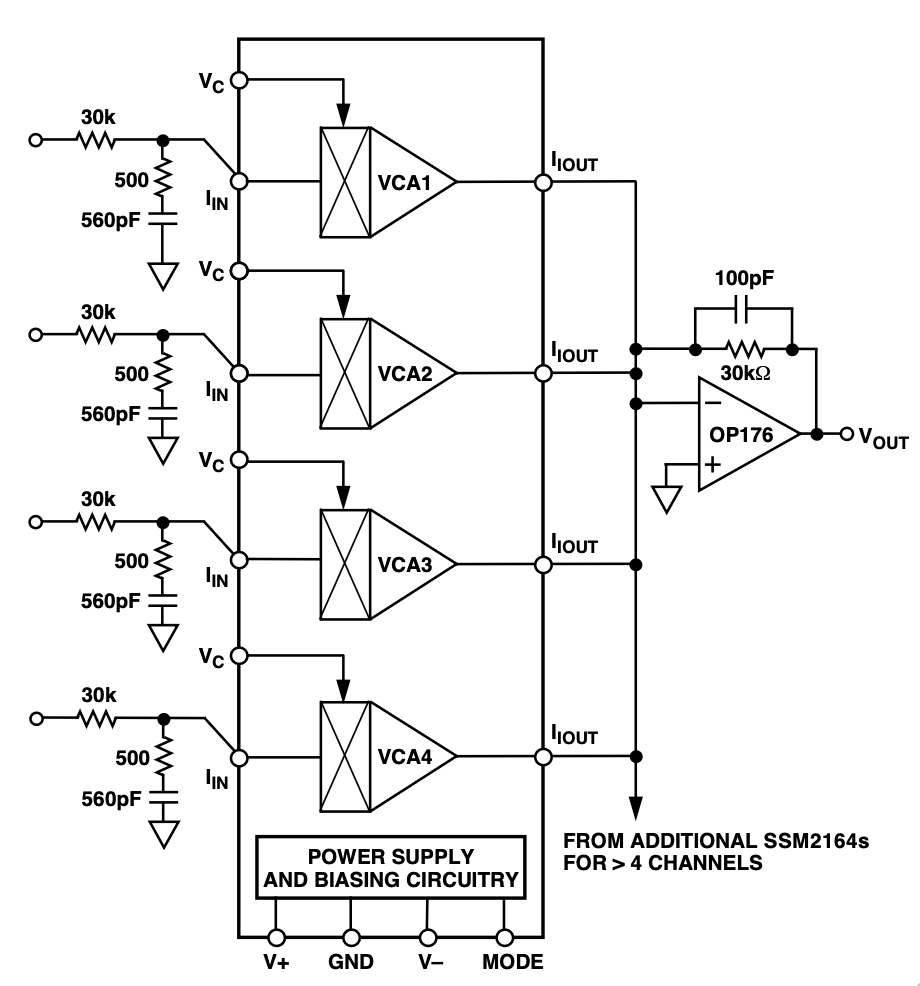
Also read the datasheet, just search for "V2164 pdf" or "SSM2164 pdf".
| Qty | Value | Footprint | References |
|---|---|---|---|
| 11 | TestPoint | TestPoint:TestPoint_Loop_D2.50mm_Drill1.0mm | TP2, TP3, TP4, TP5, TP6, TP7, TP8, TP12, TP13, TP14, TP15 |
| 6 | 33k | Resistor_SMD:R_0603_1608Metric_Pad0.98x0.95mm_HandSolder | R2, R3, R5, R6, R7, R8 |
| 6 | 470 | Resistor_SMD:R_0603_1608Metric_Pad0.98x0.95mm_HandSolder | R10, R11, R12, R13, R16, R17 |
| 4 | 100n | Capacitor_SMD:C_0603_1608Metric_Pad1.08x0.95mm_HandSolder | C1, C4, C9, C10 |
| 4 | 560p | Capacitor_SMD:C_0603_1608Metric_Pad1.08x0.95mm_HandSolder | C5, C6, C7, C8 |
| 4 | 5k | Resistor_SMD:R_0603_1608Metric_Pad0.98x0.95mm_HandSolder | R1, R4, R14, R15 |
| 2 | 10k | Potentiometer_THT:Potentiometer_Alpha_RD901F-40-00D_Single_Vertical | RV1, RV2 |
| 2 | 220p | Capacitor_SMD:C_0603_1608Metric_Pad1.08x0.95mm_HandSolder | C2, C3 |
| 2 | Conn_01x07 | Connector_PinHeader_2.54mm:PinHeader_1x07_P2.54mm_Vertical | J3, J4 |
| 2 | Conn_01x08 | Connector_PinHeader_2.54mm:PinHeader_1x08_P2.54mm_Vertical | J1, J2 |
| 2 | Jumper_2_Bridged | Jumper:SolderJumper-2_P1.3mm_Open_RoundedPad1.0x1.5mm | JP1, JP2 |
| 2 | MountingHole_Pad | TestPoint:TestPoint_THTPad_D2.0mm_Drill1.0mm | H1, H2 |
| 1 | 7.5k for class A or DNP for class AB | Resistor_SMD:R_0603_1608Metric_Pad0.98x0.95mm_HandSolder | R9 |
| 1 | In1 | TestPoint:TestPoint_Loop_D2.50mm_Drill1.0mm | TP1 |
| 1 | In2 | TestPoint:TestPoint_Loop_D2.50mm_Drill1.0mm | TP11 |
| 1 | In3 | TestPoint:TestPoint_Loop_D2.50mm_Drill1.0mm | TP9 |
| 1 | In4 | TestPoint:TestPoint_Loop_D2.50mm_Drill1.0mm | TP10 |
| 1 | SSI2164 | Package_DIP:DIP-16_W7.62mm_LongPads | U1 |
| 1 | TL074 | Package_DIP:DIP-14_W7.62mm_LongPads | U2 |


MaltWhiskey/Mega-Cube
16x16x16 PL9823 Cube with Teensy 4.0 and FlexIO driver


brickbots/PiFinder
A plate solving telescope finder based around a Raspberry PI and RPI HQ Camera
It measures 33 × 80 mm and has 2 copper layers, 1.67 mm thick.
54 parts. The full list of its parts is on this page, with links to each part's symbol and footprint where PCBKit's library has them.
From the mariosgit/V2164-TesterAndMixer repository on GitHub, at the commit this page was made from: the board is V2164tests.kicad_pcb and its schematic V2164tests.kicad_sch. PCBKit opens the board in the browser, with nothing to install.
Its repository publishes it under the MIT licence: you may reuse it on that licence's terms (keep the author's notice, and for a copyleft licence share your changes alike).